Hello readers of my blog! Today we will talk about how to properly install a manifold for a heated floor with your own hands. It would seem that the matter is not tricky, but when you are faced with this problem, you have to think about how to do it correctly, what preparation to do, what materials to choose. Thus, I decided that this article would be useful to someone, and I am devoting my efforts to this subject. In it I will answer a number of questions that will arise immediately before How to properly install a manifold for a heated floor with your own hands, and some even after that. This topic is quite broad, because before work, thorough preparation is necessary, but how to do this? And this is a separate topic. You can learn about all this in great detail in the article below. How to properly install a manifold for a heated floor
Traditional radiators, for many years considered the only possible source of heat, are gradually giving way to systems of warm floors and ceilings. Many people experience innovative methods and are very satisfied. However, heated floors can hardly be called an innovation.
They have proven themselves well and become a fairly common heating method.
Such systems can run on electricity or use hot water energy.
According to experts, a water heated floor is considered the most effective and practical to assemble with your own hands, but it is quite possible to assemble it if desired.
Unit #1 - water heating boiler
The boiler selected for installation must have sufficient power to cope with the heating of the coolant during peak operation of the circuits. In addition, it should have a small power reserve.
Approximately, this value should be the total power of all maintained heated floors, increased by 15-20%. In addition, a circulation pump is needed. Most often, it is already included in most boiler models.
An additional device may be needed only if the area of the heated room is more than 120-150 square meters. m. In case of preventive maintenance or repair of the boiler without draining water from the entire system, shut-off valves are installed at the outlet and inlet of the heating device.
Location of the collector group
To organize a heated floor, you can install a common collector or install an individual element in front of each heating circuit. In the latter option, each collector must be equipped with a flow meter , temperature controllers and several devices:
- An overflow valve that regulates the constant pressure in the pipeline, for which it discharges excess hot water into the bypass.
- Battery balancing shut-off valve, connecting the collector with the heating system. Turns on and, when necessary, turns off the fluid supply to the circuit.
- A mixing valve that determines the level of heating of the coolant.
Do not forget to choose the correct position of the collector group.
Installation systems are different. For example, for a single-pipe circuit, installing a bypass is mandatory. At the same time, it must be open all the time, so an excessive amount of hot water will be discharged directly into the radiators.
A bypass is not required during return installation. If the area of the room is small, then the collector can be placed in the secondary circuit.
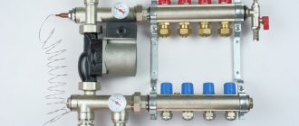
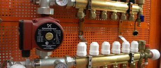
Unit #2 - collector
The collector is a device responsible for distributing hot water through heating circuits, as well as setting up and adjusting heated floors. The device must have a sufficient number of terminals to connect all circuits to them.
The simplest models are equipped only with shut-off valves. They are extremely cheap, but do not provide even a minimal opportunity to customize the system.
Devices with control valves allow you to adjust the water flow for each circuit, which allows you to adjust the heated floor for the most uniform heating of the premises.
The manifold of any model must be equipped with a drain outlet and a special air vent valve. The most convenient to use are devices with servo drives on valves, equipped with pre-mixers that mix the heated water supplied to the system with the cooled water returning and thereby regulate its temperature.
Such a device fully automates the functioning of a heated floor, but its cost is very high.
Manifold with servomotors on valves and pre-mixer. Necessary system adjustments are made automatically
Device and connection diagrams of the collector
The manifold assembly in the floor heating system ensures efficient and uninterrupted operation of all underfloor heating lines. It includes the following devices:
- pump;
- balancing valves;
- collector group;
- thermostat with sensor;
- mixing valve;
- devices that remove air bubbles in the system;
- pressure gauges.
Connection diagram for the HKV collector 4 outputs 3/4 Watts
The collector unit also includes connecting devices for pipes of various diameters.
How can water floors be installed?
Warm water floors can be laid in different ways - by laying and using concreting. Let's take a closer look at each of them.
- Concreting. The pipes through which the coolant circulates are laid as required on the prepared base and filled with concrete screed. The main disadvantages: labor-intensive “wet” work, the heavy weight of the system and the complexity of its dismantling.
- Laying method. Involves laying pipes in a specially assembled deck.
It can consist of plastic modules or wooden blocks with grooves prepared in them for installing pipes. Wooden mounting modules can also be found on sale. The main disadvantage is that the system takes longer to warm up than a concrete one.
Stages of manufacturing a distribution comb
Drawing up a heating project
When drawing up a diagram of the passage of branches and connections to the collector, many issues should be taken into account.
- How many heating branches will be suitable for the heating boiler?
- What type of heating boiler and its operating characteristics. Sometimes there are two or more heating devices.
- The number and description of the characteristics of heating devices that will be connected to the system in subsequent years (solar panels or fuel pumps, etc.).
- Description of the operation of all additional equipment, storage water tanks, feed valves, pressure gauges and thermometers, sensors and safety groups for them.
- It is necessary to determine the parameters for connecting each of the devices to the system, direct and reverse supply of warm water.
- A diagram of the entry of the pipe of each circuit into the collector is drawn up. Pipes of solid fuel boilers and additional heating boilers are usually located on the sides of the collector. If a gas or electric boiler is connected without using a hydraulic arrow, then it is also cut in from the side. If not, then it is more convenient to enter from above.
- The inlet of the heating circuit pipes is located at the top and bottom of the comb. The distance between the entrances can be made in arbitrary sizes, but it is recommended to make them 10–20 cm. To visually highlight each circuit, it is recommended to keep the gap between the direct and return entrances and keep the heating boiler the same.
- For all devices included in the system, such as pumps, modules, etc., the distance between the return flow and the outlet is indicated in the technical parameters and must be strictly maintained.
Manufacturing process
It is most convenient to make a distribution manifold from a square pipe .
First, we prepare two sections of pipe according to the given dimensions, cut the sections to create outlet pipes from molded products of round cross-section. Be sure to clean all parts from rust; it is advisable to treat them with an anti-corrosion compound.
On the body of the pipe, mark the holes for future entrances and exits, checking the diagram drawn up earlier. After checking the data, drill all holes. Next, you need to start assembling the manifold, secure all the connections between the pipes and the manifold by welding, carefully scalding all threads and pipes. After welding the selected type of fastener, knock off the scale and clean the welding areas. All that remains is to paint the collector with oil compounds to protect it from corrosion and give it a finished look.
What needs to be done before installation?
Proper installation of a warm water floor requires careful preparatory work. During their course, all the little things must be taken into account, on which the effective functioning of the structure will subsequently depend:
It is best to entrust the design of the future system to specialists, since it is quite difficult to make independent calculations.
It will be necessary to determine the length of the pipe, the pitch of its installation and the power of the heating circuit, if there are several of them, then for each separately. In this case, many nuances and parameters are taken into account. There are special calculation programs that many people use.
However, you need to understand that a flaw in the calculations will lead to a decrease in efficiency or simply the impossibility of functioning of the entire system. Equipment for heated floors must be of high quality, manufactured and purchased from a reliable company that offers good guarantees.
It will be cheaper to pay for a quality product than to subsequently constantly shell out decent sums for expensive and labor-intensive repairs. To minimize the thermal load on the screed and prevent it from cracking, the system should be divided into sections of no more than 40 square meters. m. The base for heated floors must be carefully prepared.
It must be clean and level, differences of more than 5 mm are not allowed. To prevent heat loss, a heat-insulating layer must be spread on the prepared base, with a height of 3 to 15 cm, depending on the operating temperature of the coolant. This could be special heat-insulating materials or mats designed for warm water floors. The latter can be equipped with pipe mounts, so-called bosses, which is very convenient.
A damper tape is laid around the perimeter of the room and between the installation areas, which can compensate for temperature fluctuations of the screed.
Mats with bosses designed for water heated floors are very comfortable. They not only act as a heat insulator, but also secure the pipes in place
When drawing up a laying scheme, you need to avoid a large number of pipe joints, which carry the potential danger of leaks under the floor. It is best to arrange the safest option, where connections are present only at the outlet and inlet of the collector. In this case, the length of the solid pipe should not be more than 90 m, otherwise the temperature of the circulating coolant may drop.
To use or not to use a makeshift collector
If you want to save money and you need to connect only 3 to 4 floor circuits, then it’s worth spending time making a polypropylene device with your own hands. The main thing is to reliably seal the soldering points so that leaks do not occur.
If you have a heated floor with a large number of branches, it is recommended to use brass fittings. They are more reliable, but the size of such a comb will be very bulky, but you can reduce your costs.
To summarize, we can say that a manifold assembled with your own hands, with a competent approach, will work efficiently and will be able to save the family budget from large expenses when installing a heating system. The assembly and connection of the collector group must be done strictly according to the diagram, and then the water floor will serve you for many years.
Laying a heated water floor in a screed
Work begins with determining the installation location of the collector, which is most often “hidden” in a special cabinet. It is usually mounted on the wall.
The device should be placed so that the length of pipes from each of the heated rooms is approximately the same. You can bring the collector closer to the largest contours.
The main thing is that it is installed above the level of the heated floor, without venting pipes upward, otherwise there may be problems in the air exhaust system.
The next stage is marking the prepared base, taking into account the division into sectors of 40 square meters. m. Then a thermal insulation layer and damper tape are laid.
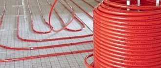
Next, the reinforcing mesh is laid on which the pipes will subsequently be attached. If special mats are chosen as thermal insulation, the mesh will not be needed. You can start laying out the pipeline.
It can be done in different ways: snake, spiral, loops, etc. The laying step varies from 10 to 40 cm, and the distance from the wall to the nearest pipe cannot be less than 8 cm.
The pipes are secured to the reinforcing mesh using plastic clamps.
It is important not to pinch the part; it should be in a loose loop, otherwise, under the influence of heat, the pipe will expand and may become deformed in the area of tight pressing. The fastening clamps are installed in 1 m increments. You must work with the pipe very carefully.
Most often it is supplied in the form of a coil. Pulling it out from there one by one is unacceptable. You should gradually, as it is laid, unwind the pipe, placing and securing the element on the floor.
There are several options for laying pipes for heated floors. The most common:
- spiral,
- snake,
- loops,
- double snail
Rotations of the part are performed very carefully, observing the minimum bend radius requirements. Typically it is about five pipe diameters. If you squeeze the product, a whitish crease area will form.
It indicates a sharp stretching of the fragment and loss of its strength characteristics, which leads to an increased risk of pipe rupture. It is not recommended to install a part with such a defect in a heated floor system. The damaged fragment must be replaced, which leads to the appearance of unnecessary joints in the pipeline, and this is also undesirable.
The laid pipes must be connected to the collector. For this purpose, special compression fittings or Eurocone systems are used.
The beginning of the pipe of each heating circuit is connected to the supply outlet of the manifold, thus the number of outlets and circuits must match. The end of the pipeline is connected to the return manifold. If the pipe is laid near an expansion joint, a corrugated tube must be put on it.
Upon completion of installation, the system must be checked.
To do this, water is poured into the pipeline and a pressure of 5-6 bar is applied throughout the day. After which a careful inspection is carried out to identify possible expansions on the pipes or leaks. More details in the video:
If the test run was successful, proceed to pouring the screed.
It should only be carried out with pipes filled with water and operating pressure in them. After pouring, the screed will dry completely no earlier than after 28 days. After this time, you can begin work on installing the flooring.
Before you start pouring the screed, the pipes are attached to the reinforcing mesh using special plastic clamps that prevent the elements from moving
There are some nuances regarding the formation of screeds over water-heated floors. They depend on the type of flooring that will be laid on top of it. If you plan to install tiles, the screed should be 3-5 cm high or the distribution of pipes should have intervals of about 10-15 cm.
Otherwise, according to the principle of heat distribution, there is a danger of the appearance of a “thermal zebra”, which can be clearly felt by the foot. But under laminate or linoleum it is better to lay a thinner screed. In this case, in order to strengthen the structure, another reinforcing mesh is laid on top of the heated floor, which will also reduce the thermal path to the surface of the coating.
You can find many recommendations on how to make warm water floors yourself.
However, you need to clearly understand that this is a complex and responsible undertaking. A pipeline laid in a screed is practically beyond repair, and if installation or design errors are discovered at this stage, it will be extremely difficult to correct them. That is why the work should be approached very responsibly, then the new heated floor will only delight you with its long and effective operation.
How to properly assemble a manifold for a heated floor
When the installation of water floor heating circuits is successfully completed, before pouring the screed, it is necessary to connect the underfloor heating pipes to the collector. This is done in order to check the tightness of the circuits and identify manufacturing defects or possible pipe defects that may arise during the installation process.
The operation of testing the pipelines must be carried out, otherwise in the event of an accident after starting the heating, the floor covering will have to be destroyed.
After the screed has been completed and the solution has hardened, it is connected to the main pipelines and the system is put into operation. How to properly assemble a manifold for a heated floor and combine it with a mixing unit will be discussed in this material.
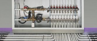
Manifold cabinet design
A manifold cabinet is a structure that includes a pumping and mixing unit and a manifold block.
Manifold for underfloor heating and heating. Review, assembly and installation of the STOUT manifold block
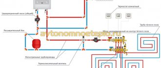
Pumping and mixing unit
This unit is designed to dilute heated water going into the water floor line with waste, cooled coolant. The pump impellers are responsible for the mixing process.
It is the pump that supplies the liquid diluted to the required degree into the system. Moving through the pipes, it gives off heat to the room and when cooled, returns to the mixing unit.
The temperature regime is adjusted using balancing valves; with their help, the flow of waste water in the pipes is also regulated. To heat a small room, the shut-off valve must be opened; if the room is small, it must be closed.
This manifold circuit for underfloor heating is equipped with a thermal head, which is responsible for the temperature level in the system. It opens or closes the heated water supply plug. When the flow of coolant stops, the bypass valve opens and the liquid moves through the free bypass.
With a simple method of tying the collector, manual temperature adjustment is done. To automate the process, a servo drive with a thermostat is used. The servo drive receives a signal from the thermostat about the temperature level in the room, and based on this indicator, it opens or closes the return manifold damper, thereby regulating the circulation of water in the floor.
Main indicators characterizing the pumping and mixing unit:
- operating pressure - maximum value 10 bar;
- temperature level - +90 degrees (maximum);
- temperature range - from 20 to 60 degrees.
Collector block
The manifold cabinet is equipped with a unit responsible for regulating the water flow, which enters the floor line and returns.
Technical indicators:
- product diameter - 1 or 1.25 inches;
- number of bends - from 3 to 12;
- pressure (working value) - 10 bar;
- The maximum heating level of the coolant is +100 degrees.
The collector block has two rows of bypasses . One, the so-called direct row, is responsible for adjusting the volume of hot coolant, the other (reverse) regulates the cooled water.
The role of the collector in underfloor heating systems
The collector is an element that underfloor heating cannot do without; all pipelines from the heating circuits are connected to it. Since the temperature of the coolant supplied to the network from the boiler room is too high for the operation of heated floors, a mixing unit always operates together with the collector, ensuring the water temperature is within 40-45 ºС.
Mixing units and manifolds for heated floors perform the task of preparing the coolant at the required temperature and supplying it to all circuits.
To understand how the entire assembly works, let’s look at the collector device in more detail. It consists of two horizontal tubes connected to the supply and return lines. The manifold body and parts are made of the following materials:
On the supply tube there are branches with thermostatic valves (actuators), and on the return there are branches with flow sensors. There are plastic caps on top of the thermostats for manual adjustment; twisting them leads to pressing on the rod and blocking the flow. Flow meters or flow sensors located on the return pipe of the manifold for a warm water floor serve to visually monitor the amount of water flowing and perform hydraulic balancing of the system.
The cheapest versions of collectors may not have flow sensors.
In order to control pressure and temperature, a thermometer with a pressure gauge is installed on the manifold, and a special valve is installed to bleed air. The kit also includes plugs, bends, taps and brackets for attaching the unit to the wall or to the metal slats of the cabinet. Many suppliers practice a complete set of the entire assembly, where there is a distribution manifold assembled with a pump and a two-way or three-way valve.
Criterias of choice
When purchasing manifolds for heated floors, it is recommended to take into account three main factors influencing the choice of product:
- Material of manufacture. Steel collectors are considered the most reliable. They are strong and durable. Brass and bronze distributors also have good reviews. Devices made of polypropylene have the lowest cost, but their installation is permissible at low heating temperatures.
- Number of circuits. This parameter must be taken into account when connecting a floor heating system. It is best to buy a manifold with an emergency outlet. This will allow you to connect additional equipment without any problems in the future or organize separation of branches if necessary.
- Adjustment method. The best option is a collector with automatic control. A device with manual adjustment can normally service the system, but such a device is not suitable for main heating systems.
Before purchasing a distributor, you must carefully study the package contents of the device and visually inspect the product to exclude the presence of cracks in its design.
Operating principle
The unit works like this: the coolant circulates through all underfloor heating circuits, driven by a pump.
The flow rate in each circuit is controlled by a valve manually or automatically, by a capillary or servo drive. When the temperature in the supply or return pipeline (depending on the circuit) drops below the set value, a two- or three-way valve begins to mix hot water from the system, and the coolant from the return flows into the general network. The figure shows a diagram of the operation of a manifold with an attached water temperature sensor and a two-way valve:
There are several operating schemes for the mixing unit, they use different parts, but its task remains the same: to maintain the required temperature in the underfloor heating system and control the coolant flow in the supply branches.
Operating principle of a manifold for heated floors
The collector is an element of the mixing and distribution unit; without it, normal operation of the heating system is impossible. Its purpose:
- distribute coolant;
- control the heating level of the liquid.
The essence of the unit’s operation is to mix the coolant coming from various heating systems and having different heating levels (warm floors, radiators). After mixing the liquid to the temperature required for hydrofloors, it is sent to the heating circuits. Having passed through the floor line, the cooled water flow, under the influence of the pump, moves into the collector, where it is mixed with the hot water, and again supplied to the floor.
The volume of flows - hot and cold - is controlled by valves. Control is carried out by temperature sensors.
This principle of operation ensures a stable and uniform level of heating of the rooms.
Recommendations for manifold assembly
It is not difficult to assemble the underfloor heating manifold, supplied as a complete set.
The tubes for the supply and return coolant are already equipped with valves and flow sensors; they only need to be twisted together if the manifold included is divided into sections of 2 or 3 branches. Then, for the convenience of further assembly, it is better to fix the tubes on standard brackets, then the distributor will be a single unit. Then plugs, connection elements, shut-off valves and control devices are installed.
The delivery set of each product includes instructions, with its help you should assemble and install the underfloor heating manifold.
The next step is to attach the collector to the wall, and after that you can install the circulation pump and valve.
There is no point in doing this in reverse order; then it will be inconvenient to attach the entire assembly. The pump and valve with a thermal head or servo drive are mounted in accordance with the selected diagram, after which the main heating pipes coming from the boiler are connected to them, and pipes from the heating circuits are connected to the outlets. There are situations when the distributor is installed not in the boiler room, but in a corridor or other room, then for installation it is better to use a decorative cabinet for the manifold.
Since the cost of a factory-made manifold is quite high, such a unit can be made independently. True, you will still have to purchase a pump and valve for the mixing part, as well as shut-off valves. The most popular way to assemble a homemade manifold is to solder it from polypropylene pipes and fittings.
This will require sections of PPR pipe with a diameter of 25 or 32 mm, tees and bends of the same size and valves. The number of fittings and valves depends on the number of heating circuits. Tools you will need are a soldering iron for polypropylene pipes with nozzles, scissors and a tape measure.
Before making a polypropylene manifold, you need to measure and cut sections of the pipe so that after connecting the tees are as close to each other as possible, otherwise the assembly will not look aesthetically pleasing.
Then taps and transitions are welded to the tees, and the remaining fittings for connection to the pump are welded to the resulting manifold.
It should be noted that a homemade manifold for heated floors, made with your own hands, will have some disadvantages.
For example, there are no thermostatic valves on the branches in the supply line, and there are no flow sensors on the return line. In their absence, the system will have to be adjusted manually, and this does not always give good results. Of course, all these elements can be installed and connected separately, but then the labor costs will be such that it is easier to purchase a finished product made of plastic, whose cost is quite affordable.
Despite the apparent complexity of the mixing and distribution unit, assembling it is not that difficult. The product usually comes with detailed instructions and should be followed. It is more difficult to make a distributor with your own hands, but this is always advisable, since you still need to buy components, and there will also be difficulties in setting up the manifold.
DIY collector
Warm floors have long been a sign of high-standard rooms.
Their use is due to the high quality of heating - the room is heated throughout the entire volume due to natural convection, since the entire floor area serves as a heater for the air in the room.
The floor itself is heated by an electric, film or good old water heater - a hot water boiler.
Manifold made of polypropylene pipes
If polypropylene pipes are used for production, you should pay attention to the presence of a reinforcing layer in them. In its absence, the plastic structure may be subject to deformation due to the current temperature conditions.
Detailed technical process for assembling the collector group:
Assembling a collector comb from polypropylene pipes
Mixing units made of polypropylene have an important advantage over their metal “counterparts” - low cost. Otherwise, you will have to come to terms with a number of shortcomings:
- Polypropylene manifolds are installed in systems with a small number of outlets (no more than 5 pieces);
- Flow meters cannot be installed;
- A larger protective box is required due to the massive structure;
- Be sure to have a set of specialized tools and soldering skills.
Assembling a distribution manifold from individual elements
For those who do not have special tools, you can assemble a comb from separate ready-made elements. It is better to select components from one manufacturer.
The circuits are connected according to the chosen scheme, adhering to the main rule - pipes with warm coolant are fixed at the top. Pipes with cooled coolant are secured from below.
At the final stage, it is necessary to carry out pressure testing and a control start-up of the heating in order to timely identify hidden or obvious deficiencies in the structure made.
Function performed
A residential building or apartment has several rooms, and in each of them a thermal circuit is laid in the floor.
It is connected to the coolant main through an input-output unit in the form of two pipes.
The need for thermal energy for each circuit is usually different: the temperature in different rooms may differ. On the other hand, the areas of the rooms are not the same, which means the volume of coolant for each room is also different.
Thus, a distributor with regulator functions must be installed between the boiler and the heating circuits. Such a device is called a collector. In terms of its functionality, it is a mixing unit. Its task is to ensure the supply of water to the circuits.
Specialist's note: the inlet temperature from the boiler can reach 80 degrees, and for a heated floor circuit, according to the standards, the water temperature should not exceed 40 degrees.
You can achieve the required value, i.e. reduce it to 40C, by mixing hot water with cooled return water.
Typically, the collector pipe has connecting nodes - according to the number of thermal circuits.
In total, the collector contains two pipes:
Hot water from the boiler is added to the mixer by turning on a thermostatic valve, which is placed in the path of water supply to the mixer. When the temperature in the mixer drops below the permissible level (we remember - this is 40°C), the valve supplies a portion of hot water.
Please note: a thermostat is installed at each outlet of the mixer comb to limit the volume of hot water for each heated floor circuit.
This group of bimetallic valves changes the flow area, as well as the volume of water passed through.
This allows you to set the temperature as desired. Flow sensors are installed at the return inlets, and the return comb is also equipped with an air vent. The coolant is pumped through the system using a water pump, which creates the necessary pressure in the line.
A complete set of manifold parts also contains various plumbing fittings. In the set of devices for warm water floors, the collector is perhaps the most important of them, as it provides:
Features of the operation of homemade collectors
If the collector is manufactured and connected correctly, then the process of its operation is simple, since the temperature level is adjusted - the supply and distribution of water along the circuits is carried out automatically. However, as a preventative measure, it is recommended to periodically conduct testing, which includes:
- checking the operability of all sections of the distribution unit;
- monitoring the tightness of connections to eliminate possible leaks;
- clarification of the coolant indicators in each loop - the degree of maximum heating, and the time to reach this degree.
Also, you should check whether the temperature corresponds to the specified values. To do this, a certain temperature is set, and readings on thermometers are periodically taken.
Homemade designs
The collector has a significant drawback - high cost.
Therefore, many “homemade” people assemble various options for collectors with their own hands, depending on their wallet and the availability of components.
There are two options for this path:
The 3-loop collector circuit can be implemented as follows:
First, you should assemble the collector pipes - return and coolant supplying the heating circuits. To do this, use one comb for 3 channels or 3 single-loop units for each manifold. The return manifold is equipped with a flow sensor or flow meter and a counter-mounted connection unit for return supply hoses along each loop.
Single-loop manifolds are connected by threaded elements into a comb. Each coolant loop contains a heat sensor with an actuator and a connection point for the power line of the thermal circuit. Air vents are connected to one end of the collectors, and at the other, a coolant pump is connected to the collector pipes, and in addition a thermostatic valve or servo drive is connected to this point, which from time to time replenishes the mixer with hot water. The collector assembly is attached to the wall, checked for functionality and connected to the thermal circuits. After this, final installation and configuration of the entire system is carried out.
Here is the simplest working version of a manifold for heated floors, available to a wide range of DIYers. The capabilities of real collectors are often expanded by connecting more complex control and metering systems.
For example, they connect heat meters, additional temperature meters and much more, no matter what - that’s why homemade inventors exist, to “assemble something yourself.”
If a homemade manifold is soldered from polypropylene pipes, then you need to replenish your arsenal of tools with a special soldering iron for welding parts made of this polymer.
When assembled by welding, the size of each single-loop unit increases due to the seams, and if there are more than 3 thermal circuits, then the entire collector becomes bulky and its installation becomes problematic. Otherwise, the design of the plastic manifold and its settings are no different from those described earlier.
Well, now it's time to finish the article. All the material I wanted to share has been reviewed. I hope it will be useful to you, and you will use it if you need to install a manifold for a heated floor with your own hands. Improve your own practical skills and gain new knowledge, as they say: “It’s never too late to learn!” That's all, thank you for your attention, successful and easy repair!
Mixing valves
Depending on the desired effect, there are various connection methods. Each of them necessarily involves the installation of mixing valves. These devices are necessary to connect hot and cold water. The latter is supplied from the heating circuit, the former from the boiler. The system can be adjusted automatically or manually, which requires additional installation of a control servo drive. There are two types of mixing valves.
Two way servo
This servo is also called the feed servo. Its main difference from conventional valves is the ability to conduct water in only one direction. If the valve is reinstalled incorrectly, it begins to malfunction and quickly fails.
“Feeding” – conducts water in one direction only
A ball or a special rod is used as a locking part for it. Adjustment is made either by turning the ball or moving the rod. Electric drives are used to carry out these manipulations.
The most popular method is a thermostatic head equipped with a water sensor that regularly monitors the temperature of the coolant. Taking into account the received data, the head turns the valve on or off. So, coolant is supplied from the return line regularly, and from the boiler - only as needed.
The operating principle of the device explains the main advantage of the manifold, which is equipped with a supply valve. Floors with this equipment do not overheat, this significantly increases their service life. The low throughput of the valve creates a smooth adjustment of the coolant temperature; significant jumps in this case are excluded.
Supply valves are characterized by ease of installation and subsequent operation. They are quite often found in the circuit of homemade manifolds for heated floors, but they have some limitations in application. It is not recommended to install two-way devices in systems that operate in rooms larger than 250 square meters.
Three-way systems
Three-way elements are designed differently. This equipment combines the operation of a bypass supply valve and a bypass valve. The valve consists of a body with one supply and two outlets. For regulation, either a rotating ball or a special rod is used.
The peculiarity of this type of device is that the adjusting part completely blocks the flow and distributes the incoming water, mixing it. The temperature is adjusted automatically; for this, the valve has a drive system that receives signals from various sensors.
Such valves have servo drives
Typically, three-way valves are equipped with actuators that are controlled by thermostatic sensors or weather-compensated controllers. The servo drive activates the locking mechanism, which is installed in the required position to obtain the required indicator of the heated coolant and return.
Weather-dependent controllers are required to regulate system power based on the weather. For example, during a cold snap, the room will begin to cool down much faster, meaning it will be much more difficult for the heating system to do its job.
To make the task easier, you need to increase the consumption of coolant and increase the temperature. The main disadvantages of three-way elements include significant throughput. Under these conditions, even a slight shift in adjustment can lead to a sharp change in water temperature.
Three-way elements are used for manifolds installed in rooms larger than 250 square meters. m and systems with a large number of circuits. Moreover, they are used for structures that are equipped with weather-sensitive sensors that determine the required floor temperature taking into account atmospheric conditions.
Time-pulse ultrasonic counters
The time-pulse method (or, in other words, phase shift) is based on measuring the travel time of a signal against the flow and in the direction of fluid movement. To convert the ultrasonic signal, two or four piezoelectric elements are installed on the pipeline, offset along the movement of water. As a rule, disk elements are used, less often - ring elements (for small diameters).
Piezo elements can be installed inside the flow (on the inner walls of a pipe or channel) or outside the pipeline (in this case, the signal passes through the outer wall). Depending on the sensors used, meters can be installed in gravity systems (both open and closed), as well as in completely closed pipelines with excess pressure of the environment. There are the following types of speed sensors:
- pipe - cut into the water supply from the outside. Can be used in pressure and non-pressure environments;
- wedge-shaped - installed on the bottom or inner wall of the pipe. As a rule, they are used in non-pressure channels or in pipelines of large diameters, if installing and servicing the sensor outside is inconvenient;
- spherical or hemispherical - mounted on inclined walls of open trapezoidal channels;
- rod - have the form of tubes, installed on the vertical walls of the channels;
- overhead – non-contact sensors, placed on the outer surface of the pipeline.
Depending on the method of installing sensors, contact and non-contact devices are distinguished. The advantage of non-contact portable flow meters is the ability to install them on pipelines without compromising their integrity. They are rarely installed permanently; they are more often used for calibration measurements at different points.
Time-pulse flowmeters are suitable for determining the flow rate of clean or slightly contaminated water (with minor inclusions of suspended particles). They are used in water supply and drainage, in cooling circuits, in irrigation schemes, at pumping pressure stations, in open natural and artificial canals and rivers. They are used for both commercial and technological accounting.
Video VALTEC manifold block
Secrets of treating joint pain from our regular reader.
My name is Genady Alekseevich. I am a stove maker with over 20 years of experience. I am engaged in both repair and construction of Russian stoves and fireplaces. I always perform the work very efficiently and carefully, which negatively affects the condition of the joints. As I grew older, the pain began to get worse, to the point where I could no longer work. Having tried many medicinal and traditional methods of treatment, I realized how serious my disease was, since there was no positive effect. Until I came across one remedy that I want to tell you about.
This is a unique mixture of the rarest and most powerful natural healing substances. This remedy has proven its effectiveness not only for patients, but also for science, which has recognized it as an effective drug. Pain in the joints and back goes away in 10-15 days, as studies have shown. The main thing is to strictly follow the instructions in the method. Order the product in its original packaging. with quality assurance available on the official website.
Dubinsky: “It is necessary to treat joint pain first of all by eliminating it.
How many times to repeat: pigment spots instantly disappear from the usual ones.
Do you want to bring your girlfriend to ecstasy. Use the trouble-free new product.
Arthritis is a direct path to disability! How to save yourself.
Electromagnetic flow meters
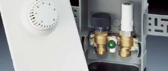
Connecting a heated floor to a thermostat
Their operating principle is based on the law of electromagnetic induction, according to which an emf is induced in an electrically conductive liquid passing through an electromagnetic field, proportional to the speed of the flow (conductor).
Such flow meters have found application in volumetric metering systems for coolant and water at industrial and energy enterprises. Disadvantage: high cost and weight for diameters greater than 300-400 mm, difficulty in removing for verification.
Rod electromagnetic water meters operate on the principle of immersing a sensor in a liquid, where the flow rate is measured. Such meters determine the flow of cold water in completely filled pipelines.
Supply valve
The valve has two positions, or two-way, and is equipped with a thermocouple. It is this part that has a temperature sensor and controls its level before being fed into the floor heating circuit. This element opens and closes the valve when boiling water is supplied from the boiler or boiler.
Two-way valves are the best option for equipping a heating system for a small living area
Often, access to cold water is constantly open, and hot liquid is supplied as needed by a safety valve. This helps protect pipes from overheating and extends the life of the entire system. In addition, the supply valve does not allow large amounts of coolant to pass through. Therefore, the water in it mixes evenly and heating occurs gradually, excluding temperature jumps.
In most cases, such a device will be the best option for installing heated floors in rooms up to two hundred square meters.
Selection, installation and adjustment of flow meters
How to make a self-leveling floor with your own hands.
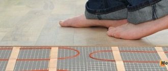
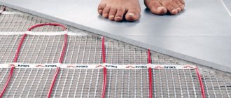
Do-it-yourself shoes for self-leveling floors A water-heated floor, as a rule, consists of several contours of plastic pipes. Hot water, moving through them, gives off its heat and returns through the return supply part of the system. The collector (comb system) of a warm water floor is designed to collect cooled water, mix and supply heated water. In other words, this is a unit that controls the operation of the floor heating system.
To regulate the temperature, flow meters are provided in the manifold. These devices control the flow of coolant, in this case water.
Why do you need a flow meter?
Theoretically, it is quite possible to do without installing a flow meter in the manifold. However, if you do not install this device, then:
- Different rooms will have different temperatures;
- There may be excessive consumption of electricity to heat water in the system;
- Different circuits will heat up unevenly.
A simple example can be given: a bathroom and a bedroom. A gas or electric boiler heats water equally for both the bath and the bedroom. But the bathroom is at least 3 times smaller in area than the bedroom.
Accordingly, the bathroom will be hot and the bedroom will be cool with the same water supply to the floor heating system. This situation is due to the fact that in the bedroom the total length of plastic pipes in the area is much greater.
It is precisely in order to regulate a comfortable temperature in the entire apartment that it is desirable to install such a device.
Advice! When installing a water heated floor, you should strive to make the contours of the pipes approximately the same length. This will save energy costs and allow you to more accurately regulate the temperature.
Principle of operation
The device is installed on the return collector outlets. When the set temperature in the system is reached, the manifold valves narrow the lumen of the energy supply or close it completely. This principle of operation is possible with full automation of the system. For this purpose, the collector is equipped with a temperature sensor.
The flow meter itself consists of several parts:
- Frame;
- Transparent flask with scale;
- Float.
The flask is usually made of durable glass; the body can be plastic or brass. The float is located inside the flask; it serves as an indicator of the coolant speed. The flow meter is also called a float rotameter.
In an automatic water heated floor collector, balancing of coolant flow is carried out using a temperature sensor. If the latter is not provided, then the rotameter can be adjusted manually.
Step-by-step instructions for installation and adjustment
H2_2
The rotameter is installed strictly vertically. To ensure that the liquid level in the flask is accurate, the collector itself is also mounted according to the level. If the comb pipe is installed crookedly, the temperature adjustment will be incorrect.
Since finishing work often occurs after installation of the collector, it is necessary to protect the assembly and its components from possible damage. The best option is to make a niche or a special cabinet for it in the wall.
Installation and adjustment:
- Using a wrench, screw the flow meter into the process inlet of the return line of the manifold;
- Turn the membrane (flask) counterclockwise to open the pressure meter;
- Remove the factory protective ring;
- Turn the brass housing ring clockwise to the desired pressure level. This is balancing the energy flow rate. The float on the scale will indicate the set value;
- Cover the brass ring with a cover plate. This must be done to avoid damage to the device, especially if the water heated floor unit is not closed in a niche or cabinet;
- Check the system operation.
During operation of the unit, the flask remains open so that the level of the water float is visible. If balancing is needed during operation, the membrane is simply turned in the desired direction.
Choosing a flow meter for water heated floors
High-quality rotameters should be accompanied by a guarantee of 5-7 years of stable operation. It is recommended to choose flow meters with a brass body
You should also pay attention to the flask; it should be made of transparent glass with good visibility of the water level scale. However, there is an opinion that it is better to choose products with a membrane made of impact-resistant plastic. When choosing a device, you need to take into account the area of the pipeline system
When choosing a device, you need to take into account the area of the pipeline system
It is also important whether the node is automated or not. In the first case, balancing will be necessary extremely rarely; mechanized collectors require closer attention
The feasibility of installing a collector system
But it is impossible to install a collector heating system in an apartment of old multi-storey buildings, because a tee heating system is already working there.
For the collector system to operate, it is necessary to close the hydraulic circuit, which is necessary to create coolant circulation in the system. If a closed hydraulic circuit is created in one apartment, then other apartments will be cut off from the heating system. The collector heating system also cannot be used in areas with unstable power supply, since when the circulation pump stops, the water will freeze and the pipes will fail. But the situation can be somewhat improved by using