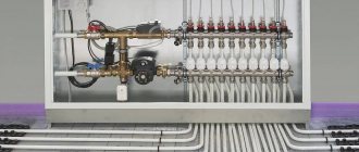
A manifold for underfloor heating is a distribution unit that redirects the coolant from the heating boiler through several circuits of the floor heating system. But depending on the configuration of the structure, it may also be assigned other functional tasks. For example, deaerating the system, adjusting the supply of coolant volumes and monitoring its flow using manual or automated flow meters. This actually ensures the maintenance of the required temperature in the heating circuits of the heated floor (HF).
Among heating system installers, due to the characteristic appearance of the collector, another slang designation for it is widespread - “comb”.
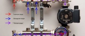
Picture 1.
Features of the operation of water heated floors
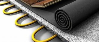
Water heated floors are used as the main or additional source of heat in private homes. The idea of this system is based on laying thermal circuits and pipelines with coolant circulating through them in the screed. The liquid is heated in a boiler and then distributed through floor loops in different rooms. The main feature of the operation of such a system is the need to maintain a low, uniform temperature across a large number of consumers. The coolant comes from the boiler heated to 60 - 70 degrees, such heat from the floors will be uncomfortable for residents. To reduce the temperature, a mixing unit is included in the system or RTL valves (reverse flow regulator) are installed.
The second feature of heated floors is associated with the uneven distribution of coolant throughout the system. The rooms have different areas, which means the contours will be of different lengths. Redistribution occurs at the collector.
Settings
As a rule, a special balancing table is attached to the diagram, on the basis of which the comb can be adjusted according to two parameters: circuit length and heating load.
The table relates the circuit number and the number of revolutions from the position of the balancing valve - “closed”. Set up the comb like this:
- remove the cap from the valve that serves to protect it;
- close the valve all the way - use a hex key for this;
- determine the number of revolutions for a given circuit;
- turn off the valve to this number;
- The remaining circuits are configured in the same way.
Correct configuration and connection of the collector are necessary for long-term operation and efficient operation of the system.
What does the collector group consist of?
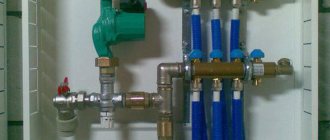
The collector has the form of a metal or plastic tube in which the coolant is collected and redistributed along the circuits. The collector group usually consists of two combs: supply and return, a pumping and mixing unit and additional equipment.
On the left is a pumping and mixing unit with a thermal head, on the right is a manifold comb with rotameters and a drain valve.
Collecting combs
The main differences between the supply and return combs are only in the shut-off valves. The heated coolant from the boiler comes to the supply, then the liquid is redistributed between the heating devices. The substance (water, ethylene glycol or propylene glycol) passes through the circuit, gives off heat and returns to the return comb, from where it goes back to the boiler.
Read more about choosing a coolant for a heating system in a separate article.
How it works?
The collector combs have a larger diameter compared to the pipes, because of this the coolant in the distribution block slows down its movement. Distribution occurs through pipes with a smaller flow. One comb can have up to 14 pipes, depending on the number of heating devices. Typically, the supply is equipped with adjusting devices to change the flow of underfloor heating circuits. More coolant will flow into a pipe with a higher throughput, and accordingly the heating devices will heat up more.
Shut-off valve options
To regulate the amount of coolant on the collector, ball valves, valves, flow meters (rotameters), thermostatic push-action valves or servos are used.
- Ball valves are shut-off valves with two positions: (open and closed), allowing you to stop the movement of the coolant through a separate pipe of the comb. Ball valves do not allow you to regulate the flow, so it makes sense to use them in heated floors, where the loops are approximately equal in length. They are also placed in front of collectors.
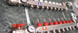
An example of a manifold with ball valves.
- The valves allow for stepwise changes in the flow diameter and require manual control of the system.
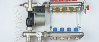
There are flow meters on the top of the supply comb, and thermostatic valves on the bottom of the return.
- Flow meter (rotameter) is a device that measures fluid flow per unit of time. It is a transparent flask with a stem inside; the mechanism of operation of the valves is similar to a regular valve.
The coolant flows along a shorter line with less hydraulic resistance - the flow meter on such loops narrows the passage, and on longer ones it widens it, due to this the floor in different rooms heats up equally.
- Thermostatic pressure valves are installed on the return comb of the underfloor heating manifold. They can close or open depending on the return temperature. The TSG valve is equipped with a Eurocone, which allows you to measure the temperature of the liquid in the pipe.
- Thermoelectric servo drive is a thermostatic head that can remotely control the operation of the comb valves. Servo drives are divided into normally closed and normally open. In the first case, in the normal position the valve is closed and opens when voltage is applied. The servo drive is connected to a thermostat, which is located in the room and responds to changes in air temperature.
The thermoelectric servo drive should not be confused with RTL valves. The first reacts to changes in room temperature, the second is adjusted to the temperature of the coolant.
Thermoelectric head with servo drive.
How to make a choice
When choosing, first pay attention to the number of circuits required for connection. When purchasing a collector device for water flooring, it is better to purchase a comb with an additional supply for one outlet. It will be needed if there is a need to split a long circuit into two branches or connect additional equipment.
You also need to decide on the type of material. The most reliable devices are made of stainless steel, natural bronze or brass. The best option would be mixing units from well-known manufacturers: Valtec, Stout or Tim.
Valtec
Tim
Stout
Should I assemble a collector or buy a ready-made one?
Collectors can be prefabricated, ready-welded or homemade. Let's consider their advantages and disadvantages.
Ready welded
They are usually produced in the form of supply and return combs welded together with a specified number of pipes.
Advantages
- Fast installation - no need to assemble fasteners.
- Minimum qualification requirements for an installer
Flaws
- Difficult to configure for a specific system.
- The number of pipes may not meet the needs, in which case they will have to be blocked off with plugs and not used.
- The collector can be equipped with elements that are unnecessary for a particular heating system. For example, it may have a hydraulic distributor (hydraulic arrow), which is only useful in networks with a large number of pumps.
- The return and feed combs may be welded together, making it difficult to attach separate loops to them. The pipes on factory mixers are usually located at the same distance from each other, but this is not always convenient.
Homemade
You can make a collector with your own hands from available materials: steel pipes with a round or square cross-section. To do this, holes are cut in them and pipes are welded. Couplings are made from round sections of smaller diameter.
Advantages
- Making a collector with your own hands is profitable from a financial point of view.
- You can make a drawing and manufacture an individual manifold for a specific system.
Flaws
- To perform this job, you will need skills in working with a welding machine.
- It will take more time.
- The non-separable design makes it difficult to repair and replace individual elements.
Prefabricated
Such distribution units are assembled from factory parts, which are purchased separately or as a kit. They will be discussed further.
Advantages
- There is variability when designing a collector unit for a specific heating system.
- Does not require special skills or equipment for installation.
- Possibility of separate dismantling of feed and return combs.
- High installation speed.
Flaws
- Components from different manufacturers may not fit together.
- This option usually costs more.
Exploitation
The layout of a heated floor collector is relatively simple. But during its operation, it is necessary to periodically check the performance of individual elements and the entire system as a whole. To do this, it is recommended to draw up a schedule for checking equipment and carrying out preventive maintenance of the following nature:
- Monitoring the performance of device elements.
- Checking the parameters of the coolant in each of the lines - speed, temperature. To do this, it is necessary to periodically take readings from control devices.
- Monitoring the integrity of the connection of pipelines to the combs, the absence of leaks and depressurization.
- Maintaining the temperature conditions of the system by taking data from thermometers.
By carrying out these simple procedures, you can maintain the uninterrupted operation of the entire system and its individual parts. But the main condition is the professional connection of the heated floor collector. The functionality of the device and its performance depend on the correctness of this installation stage.
How to install a rotameter on a manifold comb
Rotameters are often used on underfloor heating manifolds; they are necessary to control flow. Depending on the model, the device can be adjusted to different flow rates from 0 to 5 l/min. The setting is made only when the pump is turned on. It is necessary to remove the decorative protective cap and tighten the fixing nut into the desired position. After setting up the flow meter, the plug is installed in place.
Rotameters differ for the return comb and the feed comb. Inside the glass flask of the device there is a rod with a plate. In the non-working state, the rod plate is pressed to the zero value by a spring. The coolant is always supplied under the valve seat, since the flow opens the valve. On reverse rotameters the rod is at the bottom, and on feed rotameters it is at the top (the numbers will increase from above).
Differences between the rotameter on the feed and return combs.
If you confuse the supply and return rotameter, the coolant flow will press the rod against the seat, and the system will not work. Some devices do not allow you to record the required flow rate, but only measure its value; to distribute flows along the contours of heated floors, it is advisable to use the first option.
Installation process
In order to carry out installation, you must first prepare all the components. For example, VALTEC manifold systems are supplied disassembled. To get started you need:
- Use a screwdriver to remove one of the brackets for securing the device.
- Install shut-off valves.
- Screw automatic air vents onto them.
- Next are the drain valves.
- Afterwards the plugs are installed and the mounting bracket is returned to its place.
Instructions for installing the collector yourself are not particularly difficult:
- To begin with, choose a location so that the length of all heating circuits is approximately the same.
- Next, you should fix the device on the wall so that the manifold cabinet assembly for a heated floor with a liquid pump can easily fit in it, and all adjustments can be made quickly and conveniently. Usually this is a box no larger than 1x1 m in size and 12 cm thick.
- After fastening, all pipes are connected and the cabinet is assembled.
Tips and tricks
Before buying a collector, make calculations of the required length of pipes and their position. It would be better to install two 6 flow meters instead of one for 12, which will help equalize the pressure and temperature in areas that are too distant. The installation diagram of the collector must provide for its location at a level higher than the warm floor or heating circuit so that air is removed from the pipes correctly and automatically.
| Manufacturer | Cost depending on the number of flow meters, rubles | ||||
| 2 | 3 | 4 | 5 | 6 | |
| Oventrop | 4 100 | 5 150 | 6 100 | 7 000 | 8 100 |
| Watts | 3 550 | 4 650 | 5 700 | 6 750 | 7 800 |
| Kermi | 3 500 | 4 400 | 5 500 | 6 450 | 7 500 |
| Rehau | 8 200 | 9 350 | 10 700 | 12 150 | 13 550 |
| Valtec | — | 6 600 | 7 950 | 9 300 | 10 700 |
| Manufacturer | Price | |||||
| 7 | 8 | 9 | 10 | 11 | 12 | |
| Oventrop | 9 250 | 10 200 | 11 300 | 12 250 | 13 400 | 14 400 |
| Watts | 9 000 | 9 950 | 11 000 | 12 050 | 13 100 | 14 250 |
| Kermi | 8 550 | 9 600 | 10 700 | 11 750 | 12 700 | 13 850 |
| Rehau | 15 250 | 16 900 | 18 350 | 19 800 | 21 450 | 22 550 |
| Valtec | 12 400 | 13 850 | 15 250 | 17 200 | 18 050 | 19 450 |
Based on the data given in the table, we can conclude: the cost of the Kermi collector for a heated floor system today is one of the most affordable, despite the fact that it is a high-quality product from a German company, made of stainless steel.
The expensive price category is represented by the young Russian-Italian company Valtec and the German “dinosaur” Rehau. The first, which appeared in 2002, has already managed to enrich its range with brass and steel appliances and manifold cabinets. The second, having the same assortment, has more than 60 years of experience. That is why Rehau collectors for underfloor heating systems with flow meters occupy the highest price category in the table, because by trusting professionals, the chances of failure are minimal.
Mixing unit
The mixing unit can be used without a collector.
The mixing unit is often included in the collector group. Its operating principle is based on combining the supply and return flows. After passing through the heated floor loop, the medium usually has a temperature of about 30 degrees; at the mixing unit it flows into the supply flow, which allows you to get a comfortable temperature of 40 degrees.
There are many options for implementing this unit: using a three- or two-way valve, using thermostatic valves, etc. Mixers can also be prefabricated or factory-made.
The mixer usually has a thermostatic valve that measures the temperature of the medium. It is equipped with an overhead or cap sleeve. The first is simply glued to the pipe, the second is inserted into the line itself.
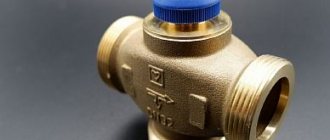
A three-way valve with a thermal head is installed in front of the pump. It is also useful to install a coarse filter on the supply before it.
- A three-way valve is installed on the supply side; using a thermostatic head, the element allows you to control two flows. There are mixing valves and distribution valves. The first one receives two streams from different sources, combines them into one and sends them along the required highway. The distribution valve receives one flow, which is distributed through several circuits. These elements are used not only to regulate the temperature of the coolant, but also to protect the boiler to prevent idling and overheating. However, the valve installation and layout will not be the same as when used in combination with a manifold.
A mixer with a two-way valve; on the bypass it is useful to install a hidden valve under a hexagon instead of an element with a handle.
Bypass is a channel between the return and supply combs; it creates a small circle and prevents the pump from working at a dead end when one of the lines is closed.
- The two-way valve is equipped with a thermostatic head and controls the flow in only one direction. When using this element in a mixing unit, an additional bypass valve will be required. In most cases, shut-off valves are placed under the hexagon. Ball valves cannot be used on this unit due to the impossibility of precise adjustment; it is also not recommended to install a valve with a handle, since someone could accidentally mess up the entire system setting.
The mixing unit is installed after the collector. A pump is placed between the collector and the boiler, which ensures movement in a small circle. The three-way mixing valve is installed on the supply line, the distribution valve - on the return line.
Location of two-way and three-way valves in the heating system
| Task | Two way valve | Three-way valve (distribution) | Three-way valve (mixing) |
| Boiler protection | — | Innings | Return |
| Temperature regulation | Innings | Return | Innings |
The mixing unit on a two-way valve can always be distinguished from a three-way valve by the presence of a valve on the bypass.
Adjusting the operation of the mixer using the example of a two-way valve
In a three-way valve, the flow is always open: if one plug closes, the other opens. In a mixer with a two-way shut-off device, only one plug closes; it works as follows: the thermal head determined that the temperature of the medium is lower than necessary, pressed the rod, the valve opened, and a portion passed into the manifold, mixing with the liquid from the return. When the temperature has reached the required values, the thermal head begins to close: the flow from the supply decreases, the flow from the bypass increases.
- The longer the heating circuit of the floor, the more the bypass valve is closed.
The bypass valve has a hidden valve for a hex key. When setting up the system, you need to close the thermostatic valve and open the balancing valve. The rotameters are adjusted, then the valve on the bypass is gradually closed until the rotameter rod begins to show that the coolant is becoming less. Fully open the thermostatic valve and tighten the balancing valve again. As soon as the rotameter plates lower or rise when turning the key on the bypass valve, balancing stops.
Self-assembly of the device
The mounting diagram is most often already present in the kit of any collector device. You can assemble a manifold for a heated floor yourself if you follow the step-by-step instructions. The device is mounted horizontally on the wall or in a pre-prepared niche, leaving free access to the main arrow of the heating pipes. Next, you will need to connect the collector to the boiler so that the heat carrier is supplied from the bottom, and the return flow is from the top. Afterwards, a bypass valve with a temperature limiter is installed, followed by a distribution comb.
Pipes passing inside the floor are fixed from above, coming from the heating system - from below. After installation, the device must be configured according to the rules, check how tight all connections are by connecting the manifold group to the main pump. Using a pump, the pressure inside the system is built up, after which the water circuit must be left in this form for a day. If all indicators are preserved, the installation was carried out according to the rules, the unit can be operated.
Do you need a hydraulic gun?
A hydraulic separator (hydraulic arrow) is a device that is usually placed between the boiler and the collector; it provides zero resistance in this area. Visually, the element is a hollow pipe with 4 pipes: on one side, two are intended for the boiler, on the other, for the collector. The question of installing a hydraulic separator arises when there is a need to install more than 4 pumps and more than 1 boiler.
The hydraulic arrow can be fixed vertically or horizontally, it does not matter. The first option is often chosen, as it simplifies the installation of the air vent in the upper part. A tap can be attached to the bottom to remove sludge.
Often in articles this device is attributed properties that it does not possess. We list the tasks for which you should not buy a hydraulic gun.
- Does not increase boiler efficiency
- Does not reduce fuel costs
- Does not protect against heat stroke
- You still need to select pumps for each circuit separately.
- Not intended for air bleeding or sludge protection.
The hydraulic arrow can worsen the operation of the system if the pumps are incorrectly selected. For example, a boiler unit is much inferior to the total power of devices on other circuits. As a result, the coolant reaches the comb already cold due to mixing with the reverse flow.
Are a manifold and mixing unit required?
In a small house, a heated floor may not take up so much, in which case the costs of a collector and mixer will not be worth it. The simplest solution would be to install a heated floor with one or two circuits, controlled by a TSG thermal head or an RTL tap. Regulation in this circuit occurs by limiting the temperature on the return flow.
The RTL valve is not intended for installation on a manifold; it has high hydraulic resistance. Due to the large size of the head, it is inconvenient to screw the element onto a distribution unit with a large number of adjacent circuits. This also makes it impossible to use built-in plumbing cabinets. It is not recommended to install RTL cranes on a circuit longer than 70 meters. The thermal head is usually placed in a plastic box that is hung on the wall.
The TSG head also limits the return flow, but has a Eurocone, so it can be installed on the return of the manifold. The actuator acts on the stem, and not on the valve itself. In this case, the head is occupied by the working valve of the manifold, because of this, installation of the servo drive becomes impossible. The absence of resistance makes it possible to install a longer circuit.
Is a collector necessary?
The main disadvantage of the device is its high cost, but it must be taken into account that without it, warm water-type coatings will not be able to function normally. This is only possible if the covering consists of one heating circuit. In modern heated floors, the length of pipes for installation cannot exceed 70 meters. Since this amount will only be enough for 7 square meters of area, for a medium-sized room you will need at least three circuits.
Most often, warm water-type coverings are installed in all rooms of an apartment or house. In this case, it will be necessary to install a collector to uniformly distribute the coolant supply. If we are talking about one small room, you don’t need to purchase a collector. It must be remembered that without this device the coolant will be supplied at the same temperature as in a general heating system. Also, without it it is impossible to remove air pockets and control pressure.
Work progress
- We install the mixer on the return comb, if an assembled factory element is used, and tighten the union nut (American) with a wrench.
- A mixer is installed on the child’s feed using the same principle.
- We install air vents for return and supply.
- Plugs are installed at the ends opposite from the mixer; they should be tightened with a wrench.
- A drain valve is installed on the comb; it is usually located under the air vent; they are designed to bleed gases from the manifold.
- For convenience, you can screw the fitting into the comb separately and then install the tap on it.
- A pump is attached between the return mixer and the supply comb.
- The fastening element is assembled; all manufacturers have their own in the form of runners or strips. If a homemade manifold is used, then the fasteners are made from improvised materials. The holders are first mounted on the combs and only then on the wall.
- The combs should be at the same distance from each other so that they are parallel on the wall. This is not a technical requirement, but more of an aesthetic consideration. To align the combs, they are first fixed to the fasteners on one side, then the same distance is measured from the other end. This is easy to achieve in short manifolds. Typically, for many manufacturers, the standard distance between combs should be 21.5 cm.
- In practice, from the point of view of system operation, it does not matter which comb is on top. In most cases, a supply distributor is placed there, but nothing will change if you put it below. The main thing is not to confuse the supply and return rotameters.
- The plug is removed from the factory return mixing unit, the thermostatic head is screwed to it, and the measuring sleeve is inserted into the supply comb mixer.
- Two mounting strips are fixed to the wall. Fasteners and hardware are selected depending on the base material. It is advisable to fix the collector at 4 points.
- The connection is made using a Eurocone. A nut is put on the pipe, then a ring, and a thrust bushing is placed in the hole. Fixation is carried out using two keys. One fixes the hexagon, the other tightens the nut. You need to do this carefully so as not to rip off the fitting.
- The contours are drawn in increments of 100 mm.
- Installation of the circuit is completed by connecting the line to the return comb. Pipes must be placed in an insulating casing. The system is filled through drain and fill valves. The ball valves on the manifold are closed.
Connection rules
In most cases, a ready-made manifold is purchased, in which all elements are selected according to technical characteristics. If you have experience in assembling such structures, you can assemble the device yourself. How to properly connect a heated floor, take into account the parameters of the overall heating system and the technical properties of the combs? To do this, you must follow certain installation rules.
Attention: First, a general connection diagram is drawn up, which indicates the dimensions of the pipes, where they are laid and connections to the heating. The throughput capacity of each comb must be calculated, their diameter and material of manufacture must be selected. The most commonly used products are stainless steel or copper.
The location of the device is selected based on the following rules:
- The highways should be approximately equal in length.
- The section of the wall where the manifold cabinet for heated floors will be installed must have free access. Furniture or other parts of the interior do not interfere with a full inspection of the device or carrying out preventive or repair work.
- The connection point of the device must be higher than other elements of the system.
A security system must be installed. It consists of an air valve and a bypass. When the temperature of water rises sharply, it expands. The air valve releases excess air, normalizing the pressure in the pipes. A bypass is necessary to quickly shut off water in case of emergency situations.
Once the installation of the collector is complete, the underfloor heating pipelines are connected to it. The quality of the joints, their tightness and reliability must be checked. The system is started before the main covering is installed. By changing the temperature conditions using the control device, the heating quality of each line is checked, and the pipes are inspected for leaks. After this, you can begin installing the flooring.
How to choose material
Before you make a water heated floor with your own hands, you should not only decide on its configuration, but also calculate the required amount of materials.
What is included with the device:
- the pump must be purchased separately if it is not included in the basic package of the boiler;
- pipes from which the wiring is made;
- pipes laid over the entire surface of the floor;
- a collector, which is responsible for adjusting and configuring the device;
- valves (ball), which are installed before entering the boiler;
- fittings that are used for laying and connecting a route consisting of pipes from the boiler to the collector;
- the water heating boiler itself.
The main material used to make pipes is cross-linked polypropylene or polyethylene. It is possible to make a warm water floor of high quality only if you use high-quality elements and materials. Polypropylene elements must be reinforced with glass fiber, since the material itself can expand greatly after heating. But pipes made of polyethylene are not subject to significant expansion. They gained enormous popularity. Pipes with a diameter of 1.6–2 cm are often used. It is also worth considering that the material must withstand a pressure of ten Bars and a temperature of 90 °C.
Floor pipe
Installation of a warm water device should not be burdened with the purchase of expensive oxygen protection or any additional layers. The main task should be based on minimizing costs, both for the installation of a water-heated floor and for the installation of individual heated elements. The collector consists of a pipe with a number of splitters. Used to connect circuits. It is recommended to install two splitters at once in the collector cabinet. The first will be responsible for distributing the hot coolant, and the second will be responsible for collecting the cooled coolant.
Manifold cabinet: purpose, types and advantages
Manifold cabinet
The manifold cabinet is a protective structure that protects the mixing unit from outside interference. Essentially, this is a box installed in a horizontal position, equipped with fastening mechanisms and a door.
The use of such a cabinet makes it possible to place the manifold unit in a convenient place without damaging the interior and technical content. Thus, the collector-mixing unit can be placed in any room without fear that children and pets will be interested in the contents.
There are two types of manifold cabinets:
External ones are mounted on the wall surface using special fasteners and legs (if necessary, height adjustments). The outlet slots are covered with removable metal plates. The cabinet itself is coated with powder paint or an anti-corrosion compound on the sides; the door can be white, beige or another color according to the consumer’s taste.
External manifold cabinet
Built-in ones are installed in a niche or covered with clapboard or plasterboard. The side parts, as a rule, are not painted, since they contain fastening and outlet spans. The facade is painted white, but options are also possible.
Built-in manifold cabinet
Both types of structures must have a strong lock and protection against possible thermal burns. Cabinets are not placed below floor level, but are not raised too high. After installing the box, the process of assembling the water floor collector proceeds according to the planned diagram. At the same time, all bends remain easily accessible for laying contours.
You can also place a water supply meter inside the cabinet, combining all the circuits at one point. On the wall, the entire structure will look many times more aesthetically pleasing than a bunch of pipes for the water circuit of a heating system with numerous sensors, valves and taps.
Where are the collection departments located?
For a heated floor system, you can install one common collector or install an individual device in front of each heating circuit. In this case, each collector must be equipped with thermostats, a flow meter and three main elements:
- A mixing valve that determines the degree of heating of the coolant in the heating circuit.
- Radiator balancing shut-off valve connecting the collector to the heating system. Opens and, if necessary, closes the water supply to the circuit.
- Overflow valve. It is responsible for constant pressure in the pipes, for which it directs excess coolant into the bypass.
Assembly schemes can be very different. For a system with one radiator pipe, for example, a bypass is required. Moreover, it must always be open, so excess hot coolant will be discharged directly to the radiator.
If there is a return circuit, a bypass is not necessary. If the heated area is small, the collector compartment can be placed in the secondary circuit.
Balancing contours and filling screed
Next, hydraulic balancing of the individual underfloor heating circuits occurs. To do this, you need to use a special adjustment key to set the value specified by the designer on the fine adjustment valves.
If you do not have such valves, then set the calculated coolant flow for each heating circuit. This is done with flow meters.
They set the flow in order to align all the contours with each other. After all, each can be any length, and your coolant must flow evenly along all circuits, and not just along the shortest one.
After pressure testing and checking for leaks, the pipes are filled with screed. In this case, the system must be filled with cold water and be under pressure.
Mistake #6 - pouring screed with empty pipes.
When the screed gains strength, thermal tests are carried out. This takes a period of time equal to 7 days.
In this case, during the first three days, the heating system is flushed with water at a temperature of 20 degrees. Over the next 4 days, the maximum operating temperature is set and the heating of all circuits is checked.
Thermal testing is also documented in a protocol.
A few words about the manufacturers
Collectors of Russian origin are made of stainless steel, and also have the maximum number of extensions - flow sensors, sockets, etc.
Europeans prefer ferrous metal. In terms of functionality, models of European origin are practically no different from Russian ones.
Manifold group with mixing unit and bypass for heated floors
Chinese models are devices without automation, that is, you will have to operate the collector manually. They are considered the cheapest and are excellent for servicing small residential buildings. Don't forget to install a three-way valve and pump if you plan to use Chinese products.
Which are the most famous and reliable manufacturers? Rehau products are a guarantee of quality and functionality. The name of this company is known to almost all manufacturers of heated floors, since its products undergo several stages of testing for strength, compatibility and safety.
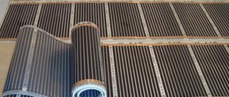
Wood flooring systems
Wooden systems are quite popular, due to their environmental friendliness, affordability and ease of installation. A convenient option for most users is modular dry heated floors, which include OSB or chipboard blocks. The blocks have special channels designed for pipe installation. A wooden dry water heated floor is easy to install, and its elements are standardized.
High-quality processed wood is used as inter-tube boards. The dimensions of the boards may vary, but standard products have a cross-section of 21x120 mm or 28x120 mm. You need to select the sizes of blocks or boards depending on the distance between the pipes. In any case, the materials will be laid on top of the logs in such a way that the existing grooves allow pipes to be laid according to the chosen pattern.
A wooden system of dry heated floors can be laid in different ways, but there is always a certain number of requirements for the base:
- Laying of logs is carried out in a certain step, the size of which depends on the floor covering used. For tiles, a step of 30 cm is suitable, and for other coatings, the laying step can be increased to 60 cm.
- There must be a waterproofing layer under the thermal insulation. Typically, a waterproofing polyethylene film of sufficient density is used, but if desired, you can use another material with similar characteristics.
- High-quality installation of heated floors in wooden houses requires the presence of good thermal insulation, which is located in the space between the joists. The easiest way to work is with thermal insulation boards made of mineral wool or expanded polystyrene. The latter option is preferable, since polystyrene foam can withstand moisture without problems. Mineral wool, when wet, loses its properties.
- On the installed joists you can build a subfloor, which must be securely fixed and have a height difference of no more than 2 mm per 1 m2. However, there is no particular need to create a subfloor, but without it, some difficulties may arise with the installation of a heated floor.
The main methods for arranging a wooden dry heated floor are as follows:
- A “floating” structure that does not have a rigid connection to the base. For this design, ready-made fiberboard blocks with pre-made gutters are suitable. These modules are laid on top of the joists, the space between which is filled with heat-insulating material. A metal strip is placed on the fiberboard and pipes are attached. The distance between the pipes and their diameter can vary depending on what kind of heat transfer the finished structure should have. If necessary, you can supplement the system with a layer of hydro or vapor barrier. In the case of soft finishes, a supporting sheet with a thickness of at least 22 mm is required so that the structure can withstand loads. In addition, the laid slabs will serve as a distributor and accumulator of thermal energy. Modules for a floating structure can also be used when laying heated floors on a flat base.
- In the second version of the system, inter-tube boards are used instead of modules. Their length may vary, but the width and thickness must be the same so that the structure can be laid out with the required pipe laying pattern. The boards can be laid on any leveled base, but it must have heat and waterproofing layers on it. With proper installation of such a structure, the thermal expansion of the materials will be completely unnoticeable.
- GRANAB system. Such a heated floor without a screed in a frame house is initially designed for installation on top of any base, regardless of their alignment (for more details: “How to make a heated floor in a frame house, which option to choose”). The key feature of this underfloor heating system is the modules mounted on height-adjustable legs. After laying out the modules, wooden blocks for laying pipes, metal elements and the pipes themselves are laid out on top of them. Further installation technology looks as usual.
Materials and tools
The set of materials and tools for arranging a heating system is as follows:
- Boiler;
- Collector;
- Pump;
- Control valve;
- Air vent;
- Valve set;
- Fitting;
- Screws;
- Screwdriver;
- Cement;
- Sand.
This set may vary depending on specific conditions, but the main components are still the same. For example, without a boiler, heating operation is simply impossible, so if it is not installed yet, this will definitely have to be taken care of. Another important element is subsequently attached to the boiler - a pump, which ensures the circulation of coolant throughout the entire circuit.
The valves are designed for installation at the equipment inlet. After installing them, you need to prepare for the long process of installing the distribution pipes. When the pipes are installed, it is the turn of the collector. The design of the collector includes a number of elements that allow you to configure and regulate the temperature regime of the heated floor.
The next item is fittings. You need to purchase the required number of fittings with which the elements of the main line will be connected. In addition, the same fittings can be used to connect the working surface to the main pipeline.
A special item on the list are the pipes from which the working surface of the heated floor will be formed. Typically, glass fiber reinforced polypropylene pipes are used for heated floors. The advantage of such pipes over conventional polypropylene pipes is a much lower coefficient of thermal expansion. You can make a reliable heated floor collector with your own hands from polypropylene, and it will last quite a long time.
However, simple polyethylene pipes can also be a good option - they practically do not expand when heated. The thickness of pipes used for heated floors should be 18-22 mm. In addition, the maximum operating pressure should reach 10 bar and the temperature should be 90 degrees.
Next comes the collector, also called a splitter. This device has taps that allow you to connect various elements of the heating system to it. The design of underfloor heating always includes two collectors - the first is mounted on the supply and supplies the system with heated coolant, and the second collects already cooled water. The design of the manifold itself, in addition to the outlets, includes valves, a device for draining the system, an emergency release valve and an air vent. Before installation, it is necessary to calculate at what height the underfloor heating collector will be most effective and safe.
Tips from the professionals
When installing this device, you should pay attention to the following recommendations:
Dimensions of a wall-mounted cabinet for a manifold unit
- the thickness of the collector box must correspond to the dimensions of the unit;
- You must remember to leave free space for bending pipes from each installed circuit. It must be provided directly under the block;
- The device box is placed at a point that is at the same distance from all contours.
If you use a ready-made collector group, you can significantly simplify the installation of this device. It is very easy to install it yourself without the help of specialists.