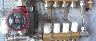
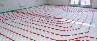
One of the best ways to ensure a comfortable temperature in a house or apartment is to install a heated floor system. This system itself consists of many elements, each of which is integral and important. But a special place among them is occupied by the distribution comb, also known as the underfloor heating manifold. Without it, the system cannot function normally and provide its owners with high-quality and comfortable heating of residential premises. Let's look at what a comb for a heated floor is, how it is designed and by what principles it works.
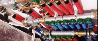
Comb for heated floors
Why do you need a comb?
What makes up the functionality and efficiency of a heating system? It should provide a comfortable temperature in all rooms of the house and the necessary heating of water. In addition, it must be safe during operation and as repairable as possible.
One of the functions of the comb is the ability to turn off the supply of coolant to a separate circuit of the heating system. This allows you to carry out repair work without turning off the heating as a whole.
All these conditions of normal operation are helped to solve by the functional element of the collector (radial) heating distribution circuit, which is called a collector or comb. Let’s say that suddenly, as happens most often, a radiator or pipe joints leak in a house. If you have a comb, you can solve this local problem without turning off all the heating. It is enough to simply shut off the required valve and turn off only the area that needs repair.
In addition, one collector, which is installed on the entire heating system of the cottage, will do an excellent job of controlling the heating process. He will also be able to regulate the temperature in each room of the house. Using this device allows you to control the heating system quite efficiently and simply. At the same time, the costs of effort and resources are reduced to a minimum.
Briefly about the main thing
The equipment of the collector block must meet the requirements for the functionality of the system. The collector device ensures uniform heating of the heating elements and a constant temperature in the room. Made from the following materials: polypropylene, brass and steel.
The manifold consists of a system to which threaded elements, fittings or control valves are connected. The collector is installed in a special cabinet or brackets are used.
Along with it, a mixing unit is used.
The durability of combs directly depends on the material and workmanship. You can purchase a ready-made distribution block or assemble it yourself from individual elements.
| Additionally The exhibition of houses “Low-Rise Country” expresses sincere gratitude to the specialists for their assistance in creating the material. – supplier of water supply and heat supply systems for any facilities, from the world's leading brands. The company also develops and installs automated metering systems for energy consumption. If you need more detailed advice, you can use the following contacts: |
Both distributor and regulator
At its core, a distribution comb is a centralized unit that allows the coolant to be distributed to its destination points. In a heating system, it performs no less important function than a circulation pump or the same boiler. It distributes heated water through the mains and regulates the temperature.
This diagram shows the general operating principle of a collector block consisting of two combs: through one, coolant is supplied to the system, and through the second it is returned
This unit can be called a temporary coolant storage tank. It can be compared to a barrel filled with water, from which the liquid flows not through one hole, but through several. In this case, the pressure of water flowing out of all holes is the same. This ability to simultaneously ensure uniform distribution of heated liquid is the basic principle of operation of the device.
Externally, the collector looks like an assembly of two combs, most often made of stainless steel or ferrous metal. The terminals available in it are intended for connecting heating devices to it. The number of such outputs must correspond to the number of heating devices served. If the number of these devices increases, the unit can be expanded, so the device can be considered dimensionless.
In addition to the leads, each comb is equipped with locking mechanisms. These can be two types of taps installed at the outlet:
- Cutting off. Such taps make it possible to completely stop the supply of coolant from the general system to its individual circuits.
- Regulatory. With the help of these taps, the volume of water supplied to the circuits can be reduced or increased.
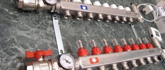
The manifold includes valves for draining water and releasing air. It is also most convenient to place measuring equipment in the form of heat control meters here. In this case, everything that is necessary for the effective operation of this node will be in one place.
Why are there two combs in the manifold block? One serves to supply coolant to the circuits, and the second is responsible for collecting already cooled water (return) from the same circuits. All elements necessary for effective operation must be on each of the combs.
Manual adjustment of TP collectors
The simplest, although time-consuming, setting method is to adjust the temperature of the heated floor using manual valves. The task is somewhat simplified by installing flow meters (rotameters) on the comb.
Flow meters simplify the dosage of the amount of circulating coolant (flow) in one separate circuit of the underfloor heating system. In the case of group temperature control throughout the collector, the rotameter can also be used to balance the flow of coolant (smoothing out the difference in hydraulic resistance) along loops of different lengths.
The main elements of a flow meter valve are:
- housing with shut-off and control valve. It is screwed into the corresponding technical hole of the manifold;
- a flask made of transparent plastic or glass with a printed scale;
- float indicator that allows you to visually control the flow of liquid through the rotameter.
Manual adjustment of the underfloor heating manifold is carried out by screwing/unscrewing manual valves or adjusting the throughput of flow meters.
Important! Improvement in the efficiency of the underfloor heating system, as a result of its manual adjustment, will be noticeable only in the case of intensive circulation of the coolant through it. This can only be achieved by using a separate heat pump.
The sequence of manually setting the temperature of a warm water floor
At the beginning of the adjustment operations, it is necessary to make sure that the pipelines of the TP system (secondary circuit) are completely filled with coolant and have no air pockets. They are filled following the main heating system (primary circuit). At this time, all shut-off and control valves on the collectors must be closed.
After opening the main valves for the supply and return of the distributors for heated floors, the shut-off devices on each of the loops are opened sequentially. Air is bled through Mayevsky valves or automatic comb air vents. It is recommended to fill the next branch only after the previous one has been completely filled and its air has been guaranteed.
Having completed filling the first loop, it is necessary to turn on the heat pump of the secondary heating circuit and circulate the coolant through its system. The efficiency of liquid circulation is checked with built-in or overhead thermometers. As a last resort, you can simply put your hands on the supply and return pipes at the same time - they should be warm, but with a slight difference in heating.
The filled first loop should be cut off from the collectors at both ends using local shut-off and control valves. Then, the above actions are carried out with the next loop.
After sequential filling of all heat pump circuits, their shut-off devices are opened and the heat pump is switched on to operating mode. The temperature of the warm water floor is adjusted through the supply of coolant to each of its branches. It is set by changing the liquid flow rate (with a valve or rotameter), and control is carried out by changing the temperature gradient between the supply and return flow. Ultimately, this difference for different circuits should be the same, within 5-15 0 C. The longer the loop, the more intense the coolant will cool and the greater its consumption is required.
Important! Heat exchange in underfloor water heating systems occurs with great inertia. The delay in heating the coating surface is especially noticeable if the pipes are laid in too thick a concrete pour (over 60-70 mm). Sometimes the effect of changing the coolant supply intensity becomes noticeable only after a few hours.
To monitor the correct adjustment of a warm water floor, it is rational to use non-contact laser or contact electric thermometers. Their installation to measure the temperature of the supply and return pipes will help reduce the time to obtain the result of changing settings from several hours to 10-15 minutes.
How to assemble a heated floor comb
It must be said that assembling a comb with your own hands is a very real task. If you installed the heating system in your home yourself, then you have enough skills to assemble this unit. Moreover, factory-made combs are supplied complete and are accompanied by installation instructions with diagrams and explanations. An example of such a diagram is presented below:
At the moment, distribution units are made of the following materials:
- brass;
- stainless steel;
- plastic (polyamide).
A factory-made plastic comb is truly a godsend; its cost is much lower than that of its metal “brothers.” Moreover, in practice it functions no worse; in any case, there are very few negative reviews about it. Assembling a distributor from any material consists of connecting the sections of the comb to each other, screwing a mixing unit from a pump with a valve to them, installing thermometers, taps and air vents. The finished collector can be installed in place and pipes connected to it.
For those who do not want or cannot purchase a plastic manifold, there is another option - to independently solder a comb from polypropylene pipes and fittings. To do this, you need to stock up on the required number of tees and sections of PPR pipes of the same diameter. Since tees cannot be connected directly to each other, pipe blanks should be cut to serve as connecting nipples.
If you have managed to solder the required number of tees, all that remains is to securely attach them to the wall, and then fit the rest of the piping around them: pump, valve, taps and other parts. We must try to ensure that the massive parts are attached to the wall independently, and do not load the distributor with their weight. True, a self-made comb will be devoid of flow meters and control valves, but if necessary, they can be purchased and installed additionally.
Manufacturing materials
The reliability and durability of the collector directly depends on the material from which it is made. A comb for heated floors can be metal or polymer. Each option has its own advantages and disadvantages.
Polypropylene
A manifold made of polypropylene pipe is an extremely economical option. In addition to the affordable price, one can note the light weight of the device. Models with fittings and combs with shut-off ball valves are available for sale. To connect metal products, combined fittings are used.
The disadvantages of polypropylene collectors include:
- thick walls, due to which the passage cross-section is smaller than that of metal combs of the same size;
- less strength and durability compared to metal models;
- oxygen permeability - even if polypropylene is reinforced with fiberglass reinforcement, there is diffusion of oxygen, which provokes corrosion of steel elements of the heating system and boiler.
Collector block made of polypropyleneSource chudopol.ru
The list of advantages of polymer combs includes:
- resistance to aggressive environments (antifreeze can be used as a coolant);
- resistance to electrochemical corrosion;
- low heat loss compared to metal products.
You can buy a polypropylene heating manifold or make it yourself from a pipe of a suitable size and fittings.
Brass
Brass is a classic material for the manufacture of heating manifolds. The comb is made using the stamping method or holes are drilled for bends and threads are cut on sections of a hollow brass rod.
Collectors made of this material have one drawback - zinc is washed out of the metal. Therefore, it is recommended to use nickel or chrome plated products. These combs:
- durable;
- resistant to corrosion and aggressive environments.
The disadvantage of brass manifolds is their high price. You can also note the smaller flow area compared to steel models.
Brass manifoldSource prom.st
Stainless steel
Stainless steel collectors are in demand due to the combination of high performance parameters and affordable prices. The advantages include:
- large flow area, making it easier to balance the underfloor heating system;
- mechanical strength even in the presence of a weld;
- resistance to corrosion and aggressive environments;
- durability.
A heating comb of a reputable brand (for example, VALTEC), made of high-quality stainless steel, is designed for 30-50 or more years of operation. Cheap products from unknown manufacturers, including counterfeits, are often made of low-quality steel and are susceptible to corrosion.
Stainless steel manifoldSource termo-snab.ru
How to install correctly
The installation of the collector is carried out depending on the location of the boiler main pipes, as well as on the configuration of the pipelines for each individual room. As a rule, the installation site is chosen to be a point equidistant from each end of the pipeline to the longest.
If it is intended to heat a sufficiently large number of adjacent rooms, then it is more expedient to provide in advance for the presence and location of several coolant separation units. Compliance with this condition will ensure optimal hydraulic operation of the entire system.
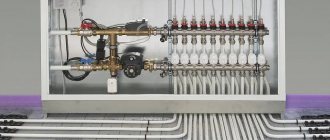
Manifold cabinet
Most often, collectors with two outlets are used, but in some cases it is necessary to install mixing units with four or more, up to twelve units. In this case, the entire structure is quite large in size, so it is very often “hidden” in a manifold cabinet, which is specially equipped for this with your own hands. It is a metal box in which the collector itself and all its components are placed (pump, mixing units, loop terminals, etc.)
It can be closed or open type. Also both built-in and wall-mounted. The first ones have a front side decorated to match the overall interior. And the latter, in most cases, have a printed powder coating.
The dimensions of the cabinet directly depend on the size of the collector, taking into account all additional elements. The optimal mounting height is about half a meter from the floor. It is not entirely rational to mount the cabinet below, since subsequently it will not be entirely convenient to insert the pipes into the manifold itself.
In addition to functional advantages, such an installation will add aesthetics to the interior of the room, and will also subsequently protect the rather expensive installation from accidental and unwanted mechanical damage.
Basement
When it is planned to use a collector simultaneously on two floors of a house that has a basement, then most often the location of the comb is determined exactly there.
Design and principle of operation
In the process of laying out the pipes of the heating circuits, their ends from all rooms converge in one place, where the heated floor comb is connected to them. It is a distribution and mixing unit whose task is:
- reduce the temperature of the coolant supplied from the boiler. To supply the floor system, you need water with a temperature of no more than 45 ° C, and the heat generator rarely heats the coolant to such a low threshold. Typically, the temperature at the comb inlet is at least 55 °C;
- provide the required amount of heat for each room. Here the distribution comb works as a regulator for the release of thermal energy, controlling the coolant flow in each circuit.
The distributor for underfloor heating visually resembles large heating combs installed in heating points. It also has 2 horizontal collectors - supply and return, to which consumers are connected, in our case - heating circuits. From the ends, coolant is supplied to the collector pipes from the main line - from the boiler room. A typical comb connection diagram is shown in the figure:
To regulate the amount of water flowing into each circuit, valves with a pressure rod are installed on one of the manifolds. Adjustment can be done either manually or using various automation tools, for example, servo drives. To control the amount of coolant, the outlets from the second collector are equipped with flow meter flasks. The comb structure is shown in detail in the diagram:
Here you can see that in addition to the elements listed above, an important part of the comb is the circulation pump. Without it, not a single circuit will be able to work, since it is the pump installed between the two collectors that is responsible for circulating the coolant through the pipes
The very principle of operation of the comb is as follows. The hot water coming from the boiler enters all circuits in the required quantity, stimulated to move by the pump. Moreover, the coolant moves in a circle until its temperature drops below the set one. Since the water temperature is controlled by a three-way valve sensor, after it decreases, the valve will begin to open the way for water from the boiler line, mixing it with the cooled coolant.
When the temperature in the manifold rises to a predetermined limit, the three-way valve will shut off the line again. The comb pump for a warm water floor works non-stop, providing circulation within the system, independent of other heating networks in the house. To empty the unit, the comb design provides for the installation of drain valves. In order to release air from this separate system, the circuit can be supplemented with automatic air vents.
Heating circuit control
With high-quality temperature control of the coolant, its flow rate remains unchanged unless additional automation equipment is installed. Without them, the volume of water passing through the circuit is adjusted only manually - by valves and rotameters located on the supply/return manifold. But thermal valves can also be controlled automatically if you install servos on them.
Servo drives are attached to thermostatic valves on the return manifold and control them at the command of the controller
The system works like this: in the rooms there are wired or wireless thermostats that monitor the air temperature and are connected to a single control unit (controller). Receiving signals from room thermostats, it opens and closes the valves on the heated floor comb using servo drives. In this way, the controller can control underfloor heating and the radiator system simultaneously, as shown in the diagram:
In addition to temperature regulation together with thermostats, the controller can do a number of interesting things:
- respond to changes in weather conditions outside;
- preheat the required premises by a given time;
- turn off underfloor heating in unused rooms;
- controlled remotely via GSM connection or the Internet.
The use of servo drives and automation equipment not only increases the comfort for residents, but also allows you to save 15-20% of the money spent on energy costs and thus reduce the cost of heating a private home.
Collector placement rules
If we are talking about a private house consisting of several floors, collectors are placed on each of them. They will be responsible for the heat supply to the rooms located on the floor on which they are installed. This helps save on fuel. These devices make the circuit of each floor autonomous. If there are rooms on one of the floors that are not used during the day, their temperature can be temporarily lowered.
However, you can adjust the temperature regime not only on the floor as a whole. Sometimes it is enough to turn off just one room or even just one radiator. This procedure will not affect the operation of all other heating devices. In addition, each radiator is heated evenly, since it receives coolant through a separate pipe that fits specifically to it.
If a heating scheme is drawn up for a multi-storey building, each floor should have its own collector, then it will be responsible for the operation of heating devices on that specific floor
Such a heat supply system may seem like a rather expensive structure, but during operation the benefits of its use become obvious. It pays for itself and the costs incurred at the installation stage will no longer seem excessive to you.
If there is a need for urgent repair of any of the circuits or a specific heating device, then the benefits of using a collector become obvious. The repairman will simply disconnect the damaged area or device from the coolant flow by closing the valve at the outlet of the distribution device.
Of course, the use of this heating system has not only advantages, but also disadvantages.
Of course, the pleasure of living in a warm place and being able to save on fuel and possible repair work is not cheap. But over time, all your initial expenses will pay off
For example:
- Significant costs at the installation stage. Plain pipes are cheaper than the high-strength steel needed to make the manifold. This must be taken into account, and then add the cost of the locking mechanisms used in the circuit. As the number of circuits increases, costs also increase in direct proportion.
- Requirement for a circulation pump. Such a pump is simply necessary for the operation of the beam circuit, and this entails increased energy costs.
- Additional expenses. If a separate branch goes to each of the heating devices, you will have to spend money on additional pipes and pay for their installation.
An increase in the volume of work will lead to the fact that it may drag on for a long time. But during operation, this system will be more reliable and efficient.
Distributor made of metal fittings
If you use metal fittings instead of polypropylene, you will be able to slightly reduce the size of the structure and do without a soldering iron. But here another pitfall awaits you in the form of cheap thin-walled tees, which are scary to handle with a pipe wrench - low-quality material can crack. If you buy high-quality fittings, then the total price of the product will be closer to the factory manifold, although the savings will still remain.
For manufacturing, you need to select internal/external thread tees made of good brass, shown in the photo, and ball valves with a low stem and a butterfly handle. The same radiator valves will go to the second part of the comb. The assembly technology is simple: pack the threads with flax or thread and twist the fittings together, and then install the taps and other parts.
Installing flow meters on a comb of brass fittings is a difficult issue. Then the supply line will have to be assembled from crosspieces and special adapters for rotameters will be installed. Some of them are also made for Eurocone, so the adapter will have to be machined. It is easier to balance the system without flow meters.
As you can see in the photo, there is nowhere to put the rotameter here
Rules for installing the comb
The location for placing the collector block must be determined at the design stage of the house. As mentioned above, if this is a multi-storey cottage, then such units should be provided on each floor. It is best to prepare special niches for them, which are located above the floor level.
However, if it was not possible to find a place for the unit in advance, you can install this unit in any room where it will not disturb anyone: in the pantry, in the corridor or in the boiler room. As long as there is no excess moisture in this place.
To keep the unit out of sight, you can place it in a special cabinet, which is offered to their customers by manufacturers of locking mechanisms. The body of this cabinet is made of metal. It is equipped with a door, and its side walls have holes for heating pipes. Sometimes the collector group is simply placed in a niche or on the wall, securing the combs with special clamps.
This comb is placed in a place specially equipped for it. As you can see, it looks quite aesthetically pleasing, and most importantly, access to this node will not be difficult
The pipes that extend from this distribution device are located in the walls or floor and are then connected to the heating radiators. If the pipes are located in the floor screed, the heating appliances should be equipped with an air vent or an air valve.
Optimal temperature parameters
The preferred temperature of the heated floor is selected according to individual needs. After all, some people like invigorating freshness in the house, while others want to bask in the warming energy flows. However, there are generally accepted standards for the preparation of coolant, heating of floor coverings and, accordingly, indoor air. They are determined by sanitary and technological requirements. These standards have already been mentioned here, however, let us briefly recall:
- The optimal floor surface temperature is 28 0 C;
- if the room is designed for a long stay of residents or there are other heating sources, then it is advisable to reduce the temperature to 22-26 0 C - this energy regime is optimal from a medical point of view. In addition, heating of the coatings is unnoticeable upon bodily contact with them, which does not cause tactile discomfort;
- for rooms where the heat supply is the only source of heating, and also where residents are present only periodically (bathroom, toilet, hallway, loggia, covered veranda), the surface temperature of the floor covering can be raised to 32 0 C.
Control elements
Setting up a heated floor collector is impossible without special devices. With their help, the optimal heating mode of the system is established and water flows in the pipelines are regulated. Each of them performs a specific function.
- Water temperature sensor
Installed on the inlet and outlet pipes of the device. These devices do not affect the operation of the system, but indicate the current heating rate. The difference in values can be useful in calculating operating efficiency. They also serve as an indicator of heating mode violations.
- Central thermostat with servo mechanism and sensor.
It is mounted on the inlet pipe of the inlet manifold and connected to the return pipe with cooled coolant. The temperature sensor is placed in the comb body. There is a rotary knob on the body of the thermostat with which you can set the required temperature level. The device receives readings from the sensor about the degree of water heating. Depending on this, the flow of cold and hot coolant is regulated.
- Servo drives on the inlet comb nozzles
According to the principle of operation, they are completely similar to a thermostat, but with minor additions. With their help, the volume of water flow for each circuit of the water floor is regulated. Depending on the model, this can be done in manual or automatic modes. For the latter, servos with built-in temperature sensors are used, which can be connected to a common remote thermostat.
- Flow meters
Devices that are optional for installation, but which, however, can become effective elements for manually controlling the operation of a water heated floor. They are installed on the return manifold pipes and are locking mechanisms with a glass bulb.
When you turn the head on the body, the rod in the device changes its position. This affects the volume of liquid passing through it. For clarity, a measurement scale is printed on the surface of the flowmeter, indicating the flow rate of water l/min.
Setting up a comb for heated floors
Factory products undergo bench testing, as evidenced by accompanying documents containing complete information about all hydrotests performed under special conditions. The use of such compact devices with a guarantee of tightness of welded and threaded connections is the best option in any in-house heating systems. Such units are characterized by an ergonomic arrangement of controls, and installation inside special mounting cabinets does not interfere with access to control valves.
After installation, the collector is configured with the servo drive and thermal head removed
The coolant from the supply pipe and the return pipe is mixed inside each outlet or directly in front of the collector, but it is advisable to entrust the calculation of the optimal circuit to specialists.
Regulating the temperature of the floor surface involves performing several sequential actions:
- Set the bypass valve to max, moving it to the 0.6 bar position. Triggering this node during the setup process causes an erroneous result.
- Calculate the balancing valve, using for this purpose the temperature indicators at the return, supply line and outlet of the heating device, under the conditions of a standard coefficient of 0.9 and according to the throughput formula: K = 0.9 × [(tk – to/tp – to) - 1]).
- Set up pumping equipment by calculating the boiling water flow rate and pressure loss on the circuits. It is allowed to set the minimum feed with a gradual addition of speed.
- Balance the branches by fully opening the control units and smoothly closing them to the required position.
It is necessary to adjust the position of the balancing valve as correctly as possible
At the final stage of setting up the comb for the “warm floor” system, the flow rate of the mixing unit is linked with other heating devices.
It should be noted that installing a flow meter will greatly facilitate obtaining accuracy when setting up all components. It is recommended to set the processing parameters of the bypass valve device approximately ten percent lower than the established maximum pressure values of the pumping equipment.
You will learn more about self-installation of a water heated floor and an analysis of various installation systems in the material:.
Comb selection criteria
The first thing you should pay attention to is what material this structure is made of. The most popular manifolds are made of brass, which are produced by casting
In this case, the result is a strong and durable part, but at the same time it is very expensive.
Welded products made of stainless steel are cheaper. The comb turns out to be quite durable, but this material can be subject to electrochemical corrosion.
Products made from high-quality plastic material are considered a budget option. Their qualities are not inferior to metal parts.
The next criterion for choosing a collector is the number of operational outlets. It is best to choose a product with outlets equal to the number of heated circuits, so that you do not have to plug extra holes.
Next, the technical equipment of the collector is taken into account for automation and regulation of coolant temperature. If you need a comb that will last you a long time, then brass is your option.
If you need a comb that will last you a long time, then brass is your option.
Today, there are combs that can be connected to thermostats and programmable controllers. With their help, it is much easier to make adjustments, as well as control the quantity and quality of coolant in the circuits.
Manufacturing companies
Different countries and companies are producing such devices. The highest quality devices are from European manufacturers, but their prices are very high - from $1000 to $1200. Products from a Chinese manufacturer are inexpensive, but they are not durable. However, there are companies that produce high-quality models at low prices.
List of manufacturers of combs for heated floors that you need to pay attention to when choosing a distribution unit:
- Millennium is a Chinese-made comb that is functional and affordable.
- TIM (China) - manifold with flow meters for water floors. A high-quality, reliable product produced using European-class equipment.
- Oventrop Multidis is a stainless steel distribution structure with forced circulation and has a long service life. Country of origin: Germany.
- Stout is an Italian-made device with flow meters. Reliable, made of quality material.
- Valtec (Italy) - nickel-brass manifold. At the outlet, the comb is equipped with taps to control the coolant flow.
How to build a collector yourself
You can buy a ready-made connection, choosing one that would approximately meet the needs of your home. But achieving an exact match is quite difficult. Therefore, it is better to make a heating comb yourself. Let's figure out what is needed for this.
Planning stage
There are a number of parameters of the heating system of the house that you should know when building a unit.
- The number of circuits through which heated water will pass.
- The number and technical characteristics of the heating equipment included in the scheme.
- Additional equipment involved in installation. This refers to pressure gauges, thermometers, taps, storage tanks, valves, pumps, etc.
It is also necessary to provide for the possibility of increasing the load if over time it is necessary to build in elements that were not taken into account in advance. This could be, for example, solar panels or a heat pump.
It is necessary to foresee in advance not only the number of circuits operating in the heating system, but also additional equipment that will be included in the overall scheme
Determining the block design
The design of the future node depends on the connection point of each circuit. After all, there are some connection nuances that cannot be ignored.
- Boilers (electric and gas) must be connected to the comb from above or below.
- The circulation pump should be connected from the end of the structure.
- Solid fuel units and indirect heating boilers also need to be cut in from the end.
- The supply circuits of the heating system are connected from below or from above.
For clarity, it is necessary to make a drawing of the future compact and neat unit. This will help determine the quantity and types of materials we will need. All necessary dimensions and threaded connections with thread pitch are also applied to the drawing. All circuits should be marked to guide the drawing when connecting.
This drawing shows a four-way manifold. You may not make a drawing and will limit yourself to a sketch, but do not forget to put on it all the dimensions necessary for the work
The distance between the nozzles of both combs should be from 10 to 20 cm. These are the optimal parameters for maintenance. The distance between the supply and return combs themselves should be within the same limits.
Sequence of work
To make both combs, not only round, but also square pipes can be used. The sequence of work performed is as follows:
- In full accordance with the parameters indicated on the drawing, we purchase all the necessary materials.
- According to the drawing, we make the connection by welding pipes, taking into account their subsequent functions. Welding areas should be cleaned with a wire brush and degreased.
- Testing a homemade unit is a necessary stage of work. To do this, all pipes are hermetically sealed except one, through which hot water is poured into the system. Let's take a good look at all the joints: they shouldn't leak.
- Now the collector can be painted and dried thoroughly.
- Next, you should connect pipes, locking mechanisms and control equipment to it.
After this, the device is ready for use
This will differ favorably from purchased products in that it is built taking into account the needs of a particular home, and this is very important for its further operation. Of course, a high-quality and functional device can only be obtained if the master knows how to handle a welding machine and metalworking tools
In order for a homemade collector block to work more efficiently than a purchased one, the master needs to be able to handle both welding equipment and plumbing tools
You can learn how to make a polypropylene manifold by watching this video:
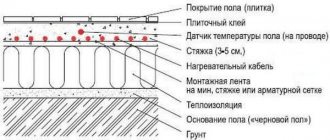
Heating rooms using water heated floors is considered one of the most effective ways in terms of energy savings and uniform heat distribution. As you know, heating is carried out through pipes with coolant laid in a screed. Each room is a separate closed circuit, or even several. Their operation is controlled by one common unit - a comb for heated floors. Information about how this unit functions, the nuances of its assembly and regulation is brought to your attention in this article.
The influence of the coolant supply method on the choice of control technology
Control of heating of water heated floors equipped with their own heat pumps occurs under conditions of continuous supply of coolant at high speed and in large volumes. Such systems use the admixture of cooled liquid to the supply stream to bring its energy parameters to the specified ones. The mixing is carried out in pumping and mixing units (PMU), which lower the temperature of the coolant from the primary high-temperature heating circuit to the design ones. Further adjustment of the temperature of the heated floor is carried out on the combs and has already been described above. NSU blocks provide optimal operating conditions for underfloor heating, and also allow it to be installed in unlimited areas.
However, with a small TP quadrature it is possible to avoid the use of expensive mixing units. The temperature of the coolant for the heated floor, in this case, is maintained by the method of limiting flows or by the RTL scheme. The functional principle of the circuit is the portion supply of coolant into the circuits. In each branch, the active element of the thermostatic valve, installed on the return line, having warmed up to the set temperature maximum, blocks the flow of working fluid. The heat gradually released by the coolant is dissipated in the concrete screed. After the system has cooled to the minimum temperature threshold, the valve opens and the batch feed cycle is repeated.
The simplicity of RTL control of underfloor heating makes it especially attractive. After all, it is enough to use a set of thermomechanical valves installed on the comb, or compact “unibox” type assemblies. However, when choosing an RTL scheme, you should not forget about its limitations:
- it is applicable only in heated floors made under a thick concrete screed, which plays the role of a heat accumulator;
- For efficient operation, in addition to good heat removal, the circuit pipelines must have minimal hydraulic resistance. This is necessary to quickly update the coolant. Taking into account the absence of a heat pump in the TP system, such conditions are met if the length of the branches does not exceed 50 m with a pipeline diameter of 16 mm. If it is necessary to slightly increase the length of the circuits, it is recommended to use pipes Ø 20 mm.
Important! The use of pipes of different diameters in one system (on one collector) of underfloor heating with RTL control is strongly not recommended.
Working with Manifold Flow Meters
Hydraulic balancing of underfloor heating loops involves normalizing the flow in each coil. Depending on the length, different amounts of incoming coolant may be required so that when passing through the loop it cools exactly to the calculated value. The required flow is quantitatively determined as the ratio of the thermal load on the loop to the product of the heat capacity of water or other coolant and the temperature difference in the supply and return: G = Q / s * (t1 - t2).
You can often find recommendations to determine the coolant flow according to the performance of the circulation pump, that is, to divide its supply in proportion to the ratio of the lengths of the loops. Such advice should be avoided: in addition to the fact that it is quite difficult to calculate the length of each coil, one of the most important rules is violated - choosing equipment parameters based on the needs of the system, and not vice versa. Attempts to distribute flow in the described manner almost always lead to the fact that the flow in the loops differs significantly from the calculated values, which makes further adjustment of the system impossible.
Adjusting the flow with flow meters is quite simple. In some models, the throughput is changed by turning the body, in others - by rotating the rod with a special key. The scale on the flow meter body indicates the flow rate in liters per minute; you just need to set the float to the appropriate position.
Almost always, when the capacity of one flow meter changes, the flow rate in the remaining loops changes, so the adjustment is carried out several times, sequentially calibrating each outlet. If such changes are particularly pronounced, this indicates a lack of capacity of the control valves through which the collector is connected, or that the performance of the circulation pump is too low.
What does the comb consist of?
Having decided on the adjustment method, having decided whether a three-way valve or thermal heads will be used, the remaining elements of the comb are assembled.
- The collector itself is two parallel tubes (supply and return) with outputs. One side of each comb is plugged. It can be purchased ready-made, but its cost is the main cost of the mixing unit (we are talking about thousands of rubles). It is much cheaper to assemble a comb from a series of tees, which have an internal thread on one side and an external thread on the other. The circuit tubes are connected to the side outlets (via fittings - crimp or solder).
- Manometer that controls pressure.
- Burst valve , which will operate if the pressure is exceeded.
- Servo drives for each circuit are especially important when the length of the circuits is different (if you give free rein to the laws of physics, the temperature in them will be significantly different). Thermostats equalize pressure and temperature.
Installation of the comb in the heating system and its calculation
Comb in a water heated floor system
The installation location of the distribution comb in the heating system depends on its purpose. Most often it is used to organize multi-circuit heat supply. However, in addition to this, it is a mandatory element of a water heated floor.
Before proceeding with installation, you should calculate the heating comb. The main task of this process is the uniform distribution of pressure along the heating circuits. If the system is a complex circuit of highways, it is recommended to make calculations using special programs. For a simple system with up to 5 circuits, you can apply the principle of equal sections.
N0=N1+N2+N3+N4
Where N0 is the diameter of the collector, N1, N2, N3, N4 are the sections of its outlet pipes.
The same calculation scheme is used when making a heating comb with your own hands
It is important that the dimensions of the inlet and outlet manifolds match. It is noteworthy that the standard heating comb device has no requirements for its shape
Those. it can be either round or square. The basic principles for installing collector heating are as follows:
- To improve circulation, it is recommended to install pumps for each circuit. In this case, the distribution comb of the heating system should not ensure synchronization of the pumps;
- If the unit is located in a boiler room, installation of a protective box is not necessary. An exception is the installation of a heating comb made of polypropylene in a heated floor system;
- To adjust the coolant volume, it is necessary to install control fittings on each inlet and outlet pipes - inlet valves and balancing flowmeters;
- When planning the installation of a heating comb, it is necessary to provide for the presence of a safety group at the distribution unit.
An example of a heating comb installation diagram
It should be remembered that these are only general recommendations that can be changed and supplemented depending on the specific parameters of the heating system.
In addition to these rules, experts advise when calculating the heating comb to take into account the difference in the length of the circuits. It is recommended to draw up a diagram so that their length is approximately equal.
To reduce energy consumption, a mixing unit can be installed in the heating comb device, which, in turn, will reduce heating costs.
Mixing unit
The mixing unit can be used without a collector.
The mixing unit is often included in the collector group. Its operating principle is based on combining the supply and return flows. After passing through the heated floor loop, the medium usually has a temperature of about 30 degrees; at the mixing unit it flows into the supply flow, which allows you to get a comfortable temperature of 40 degrees.
There are many options for implementing this unit: using a three- or two-way valve, using thermostatic valves, etc. Mixers can also be prefabricated or factory-made.
The mixer usually has a thermostatic valve that measures the temperature of the medium. It is equipped with an overhead or cap sleeve. The first is simply glued to the pipe, the second is inserted into the line itself.
A three-way valve with a thermal head is installed in front of the pump. It is also useful to install a coarse filter on the supply before it.
- A three-way valve is installed on the supply side; using a thermostatic head, the element allows you to control two flows. There are mixing valves and distribution valves. The first one receives two streams from different sources, combines them into one and sends them along the required highway. The distribution valve receives one flow, which is distributed through several circuits. These elements are used not only to regulate the temperature of the coolant, but also to protect the boiler to prevent idling and overheating. However, the valve installation and layout will not be the same as when used in combination with a manifold.
A mixer with a two-way valve; on the bypass it is useful to install a hidden valve under a hexagon instead of an element with a handle.
Bypass is a channel between the return and supply combs; it creates a small circle and prevents the pump from working at a dead end when one of the lines is closed.
- The two-way valve is equipped with a thermostatic head and controls the flow in only one direction. When using this element in a mixing unit, an additional bypass valve will be required. In most cases, shut-off valves are placed under the hexagon. Ball valves cannot be used on this unit due to the impossibility of precise adjustment; it is also not recommended to install a valve with a handle, since someone could accidentally mess up the entire system setting.
The mixing unit is installed after the collector. A pump is placed between the collector and the boiler, which ensures movement in a small circle. The three-way mixing valve is installed on the supply line, the distribution valve - on the return line.
Location of two-way and three-way valves in the heating system
| Task | Two way valve | Three-way valve (distribution) | Three-way valve (mixing) |
| Boiler protection | — | Innings | Return |
| Temperature regulation | Innings | Return | Innings |
The mixing unit on a two-way valve can always be distinguished from a three-way valve by the presence of a valve on the bypass.
Adjusting the operation of the mixer using the example of a two-way valve
In a three-way valve, the flow is always open: if one plug closes, the other opens. In a mixer with a two-way shut-off device, only one plug closes; it works as follows: the thermal head determined that the temperature of the medium is lower than necessary, pressed the rod, the valve opened, and a portion passed into the manifold, mixing with the liquid from the return. When the temperature has reached the required values, the thermal head begins to close: the flow from the supply decreases, the flow from the bypass increases.
- The longer the heating circuit of the floor, the more the bypass valve is closed.
The bypass valve has a hidden valve for a hex key. When setting up the system, you need to close the thermostatic valve and open the balancing valve. The rotameters are adjusted, then the valve on the bypass is gradually closed until the rotameter rod begins to show that the coolant is becoming less. Fully open the thermostatic valve and tighten the balancing valve again. As soon as the rotameter plates lower or rise when turning the key on the bypass valve, balancing stops.
Product installation features
When installing this structure, it is necessary to take into account a number of rules and features. Typically the collector is installed on the wall, in the middle or closer to the floor. To do this, it is best to use a special manifold cabinet, which gives a more aesthetic appearance to the structural unit.
It must have holes drilled for suitable piping. The comb is attached in such a way that it is possible to bleed air from the heating circuits. This will allow you to carry out repairs without problems in the event of an accident.
The length of the contours should be approximately the same to make adjustments easier. This is done based on two indicators: coolant flow and temperature. For this purpose, a flow meter and temperature sensors are built into the circuit.
An important condition when installing heated floors is that the total length of each circuit should not exceed 60 m. Otherwise, it will be difficult for the coolant to overcome the hydraulic resistance in the pipelines
When creating a warm floor, each room has its own separate heating branch.
This is due to the fact that there are restrictions on the length of one branch, as well as ease of installation.
The distribution of coolant from a single boiler flow to each branch occurs in a special unit called a manifold, or comb for heated floors.
With your own hands, you can make an analogue to a factory manifold, which will perform its functions no worse, but for less money. What you need to buy, how to assemble and install it correctly in practice.
Tips for choosing
If you decide to buy a manifold for heated floors, you need to choose it according to the following criteria:
- For how many circuits is it intended? That is, how many separate branches of the heated floor are planned (the radiator branch does not count).
- Equipment. Even just buying all the parts separately and assembling them yourself will cost less. But with a ready-made, assembled comb there is a minimum of hassle.
- Material. Collectors are available in metal (steel, copper, brass) and plastic. Plastic ones can be used for simple systems with a short circuit (for example, for a toilet or kitchen).
- Adjustment. Even on factory models there are manual control valves (rather than servos).
Conclusion
A simple comb without servos is not very expensive.
By purchasing all elements, valves and regulators separately, you can indeed save money, but the risk of errors and leaks increases if the connections are of poor quality. So, when deciding whether to make a comb yourself, weigh everything carefully.
Two way valve design
In the heated floor installation scheme, the valve is installed directly in front of the comb. It is connected to a temperature sensor, which is placed at the coolant return manifold. In addition, the distribution node diagram includes:
- circulation pump;
- balancing valve;
- check valve
The check valve is part of the comb.
At the beginning of the heating process, the device is open and the coolant enters the collector. The valve remains open until the water temperature reaches the operating value. As soon as this happens, the “sensor + thermal head” tandem will close it, and the coolant will stop flowing from the heating boiler.
During this period, the floor heating comb pump will independently circulate hot water through the heating circuits. In this case, the coolant will gradually cool down, and when its temperature drops below the operating temperature, the valve will open again.
Proper mixing of hot and chilled water occurs due to a balancing valve that regulates the volume of waste coolant.
Conclusions and recommendations
Judging by the reviews on the forums, homeowners are familiar with combs equipped with a mixing unit and a pump. It is noteworthy that not all craftsmen know about the existence of RTL-type thermal heads. And they can significantly reduce the price of a heated floor comb installed in a small or medium-sized country house (up to 250 m²). Here are the recommendations:
- If possible, use a factory or homemade comb with RTL thermal heads, then you won’t have to buy a circulation pump and valves. The main condition is that the length of the contours is no more than 60 m.
- If the number of loops reaches 10 or more, and the supply line from the boiler is quite long, select a more powerful main pump. You can install the Grundfos Alfa-2 15-60 unit with the Autoadapt function to save electricity.
- For circuit lengths up to 100 m, house area over 250 m² and a complex heating system, use a comb with a two- or three-way valve (quality control).
- If possible, equip the comb and underfloor heating system with automation. To do this, it is recommended to consult with a specialist in this field.
Note. Designers and manufacturers of components for heated floors categorically do not recommend making the pipe length in one loop more than 100 m (Ø16 mm).
It is advisable to avoid a situation where the distribution comb is on the 1st floor, and heated floors are installed on the 2nd and 3rd floors. It is better to place the node closer to the contours and run 2 lines to it, instead of laying 10 or 20 pipes from the comb along the walls and through the ceilings. You will get answers to many questions by watching the video:
How does the collector work?
Water floors are laid in various ways, for example, concrete or flooring, but regardless of the technology chosen, it is necessary to purchase and install a manifold cabinet.
Note: It is recommended to install the collector box on the wall as close to the middle as possible and most often near the floor.
In the future, two pipes will be inserted into it:
- supply, which leaves the boiler and supplies hot coolant to the system;
- return, which performs an absolutely opposite role: it serves to collect water that has already been used and has had time to cool. It is returned back to the boiler, and the process is repeated again.
The cyclical nature of the process is ensured by another built-in component of the system - a circulation pump. One way or another, during the operation of a heated floor, say during repair work, the system has to be turned off. To do this, each of the pipes is equipped with shut-off valves. A plastic pipe and a metal shut-off valve are connected to each other through a compression fitting. Then a comb is connected to the valve, mounting an air vent on one end and a drain valve on the other. After assembling the cabinet, they proceed directly to installation. And only with a comb already installed on the wall can you cut the circuit pipes to length.
Note: To ensure the tightness of the connection, the pipes are cut strictly at a right angle.
How to build a collector yourself
You can buy a ready-made connection, choosing one that would approximately meet the needs of your home. But achieving an exact match is quite difficult. Therefore, it is better to make a heating comb yourself. Let's figure out what is needed for this.
Planning stage
There are a number of parameters of the heating system of the house that you should know when building a unit.
- The number of circuits through which heated water will pass.
- The number and technical characteristics of the heating equipment included in the scheme.
- Additional equipment involved in installation. This refers to pressure gauges, thermometers, taps, storage tanks, valves, pumps, etc.
It is also necessary to provide for the possibility of increasing the load if over time it is necessary to build in elements that were not taken into account in advance. This could be, for example, solar panels or a heat pump.
It is necessary to foresee in advance not only the number of circuits operating in the heating system, but also additional equipment that will be included in the overall scheme
Determining the block design
The design of the future node depends on the connection point of each circuit. After all, there are some connection nuances that cannot be ignored.
- Boilers (electric and gas) must be connected to the comb from above or below.
- The circulation pump should be connected from the end of the structure.
- Solid fuel units and indirect heating boilers also need to be cut in from the end.
- The supply circuits of the heating system are connected from below or from above.
For clarity, it is necessary to make a drawing of the future compact and neat unit. This will help determine the quantity and types of materials we will need. All necessary dimensions and threaded connections with thread pitch are also applied to the drawing. All circuits should be marked to guide the drawing when connecting.
This drawing shows a four-way manifold. You may not make a drawing and will limit yourself to a sketch, but do not forget to put on it all the dimensions necessary for the work
The distance between the nozzles of both combs should be from 10 to 20 cm. These are the optimal parameters for maintenance. The distance between the supply and return combs themselves should be within the same limits.
What is it needed for
When installing water pressure systems, there is a rule: the total diameter of all branches should not exceed the diameter of the supply pipe. In relation to heating equipment, this rule looks like this: if the diameter of the boiler outlet fitting is 1 inch, then the system allows two circuits with a pipe diameter of ½ inch. For a small house heated only with radiators, such a system will work effectively.
In fact, there are more heating circuits in a private house or cottage: heated floors, heating of several floors, utility rooms, and a garage. When they are connected through a tapping system, the pressure in each circuit will be insufficient to effectively heat the radiators, and the temperature in the house will not be comfortable.
Therefore, branched heating systems are made using collector systems; this technique allows you to adjust each circuit separately and set the desired temperature in each room. So, for a garage, plus 10-15ºС is enough, and for a nursery, a temperature of about plus 23-25ºС is required. In addition, heated floors should not heat up more than 35-37 degrees, otherwise it will be unpleasant to walk on them, and the floor covering may become deformed. With the help of a manifold and shut-off temperature, this problem can also be solved.
Video: using a collector system for heating a house.
Manifold groups for heating systems are sold ready-made, and they can have different configurations and the number of outlets. You can select a suitable collector assembly and install it yourself or with the help of specialists.
However, most industrial models are universal and do not always fit the needs of a particular home. Redesigning or modifying them can significantly increase costs. Therefore, in most cases it is easier to assemble it from separate blocks with your own hands, taking into account the characteristics of a particular heating system.
Manifold group for heating system assembly
The design of the universal collector group is shown in the figure. It consists of two blocks for forward and reverse coolant flow, equipped with the required number of outlets. Flow meters are installed on the supply (direct) manifold, and thermal heads are located on the return manifold to regulate the return water temperature in each circuit. With their help, you can set the required coolant flow rate, which will determine the temperature in the heating radiators.
The manifold distribution unit is equipped with a pressure gauge, circulation pump and air valves. The supply and return manifolds are combined into one unit with brackets, which also serve to attach the unit to a wall or cabinet. The price of such a unit is from 15 to 20 thousand rubles, and if some of the bends are not used, its installation will be clearly impractical.
The rules for installing the finished block are shown in the video.
Comb - collector unit
The most expensive elements in a manifold distribution block are flow meters and thermal heads. To avoid overpaying for unnecessary elements, you can buy a collector unit, the so-called “comb”, and install the necessary control devices with your own hands only where necessary.
The comb consists of brass tubes with a diameter of 1 or ¾ inches with a certain number of taps with a diameter of ½ inch for heating pipes. They are also connected to each other by a bracket. The outlets on the return manifold are equipped with plugs that allow you to install thermal heads on all or part of the circuits.
Some models may be equipped with taps, with their help you can regulate the flow manually. Such combs have a cast body and are equipped with a fitting/nut thread at the ends, which allows you to quickly and easily assemble a manifold from the required number of branches.
In order to save money, the manifold for heating systems can be assembled from individual elements independently or completely made by hand.