Owners of private country houses quite often began to abandon the traditional two-pipe distribution of the intra-house heating system, preferring a system of collector distribution of thermal energy. This is not just a fashionable trend in household heat energy, it ensures the economical use of fuel to generate a unit of thermal energy.
The system is guaranteed to provide the proper level of heating of all premises of a residential building according to the schedule established by the owner. Previously, when arranging heat supply systems, the main heat supply was taken as a basis, which could not provide high-quality heat supply - buildings close to the heat source overheated, and distant consumers froze. The same thing happened in the in-house heating systems of an apartment building, when the outer risers remained cold for many years.
Today, this problem is successfully dealt with by a collector system for distributing coolant, which has a more common name among specialists - distribution combs for heating. Owners of private households will not face any particular difficulties in switching to this system. The same cannot be said about multi-storey and apartment buildings, which for its implementation will require 100% replacement of intra-house distribution pipelines.
Why do you need a comb anyway?
What makes up the functionality and efficiency of a heating system? It should provide a comfortable temperature in all rooms of the house and the necessary heating of water. In addition, it must be safe during operation and as repairable as possible.
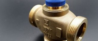
One of the functions of the comb is the ability to turn off the supply of coolant to a separate circuit of the heating system. This allows you to carry out repair work without turning off the heating as a whole.
All these conditions of normal operation are helped to solve by the functional element of the collector (radial) heating distribution circuit, which is called a collector or comb. Let’s say that suddenly, as happens most often, a radiator or pipe joints leak in a house. If you have a comb, you can solve this local problem without turning off all the heating. It is enough to simply shut off the required valve and turn off only the area that needs repair.
In addition, one collector, which is installed on the entire heating system of the cottage, will do an excellent job of controlling the heating process. He will also be able to regulate the temperature in each room of the house. Using this device allows you to control the heating system quite efficiently and simply. At the same time, the costs of effort and resources are reduced to a minimum.
Criteria for selecting a finished structure
When there is no desire or opportunity to make a distribution comb yourself, you can choose and buy a ready-made device. It will cost significantly more than a homemade one, but it will help save several hours that it would take to create a comb with your own hands.
When purchasing a product, you should pay attention to many factors that can affect the efficiency of the entire heating system.
The most significant among them are:
- Material. First you need to decide what the distribution comb will be made of. Manufacturers produce steel, polypropylene, and non-ferrous metal products. Each option is used for a specific type of heating system and helps to achieve maximum efficiency with minimal heat loss.
- Bandwidth. The value of this parameter determines how well the comb will cope with the functions assigned to it. It is important to choose an option that will facilitate the unhindered movement of coolant through all components of the system.
- Pressure. When purchasing a device, you should take into account not only the operating pressure in the system, but also possible differences. The device must be designed to change this indicator and continue to operate even with minor fluctuations.
- Energy consumption. For low-income people, this parameter is one of the most important. Most of the financial costs go to pay for electricity, which ensures the operation of all systems.
- Possibility of expansion. It is very important to provide for it, since new heating devices may appear in the house, which will need to be connected to the system.
Both distributor and regulator
At its core, a distribution comb is a centralized unit that allows the coolant to be distributed to its destination points. In a heating system, it performs no less important function than a circulation pump or the same boiler. It distributes heated water through the mains and regulates the temperature.
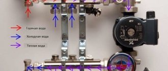
This diagram shows the general operating principle of a collector block consisting of two combs: through one, coolant is supplied to the system, and through the second it is returned
This unit can be called a temporary coolant storage tank. It can be compared to a barrel filled with water, from which the liquid flows not through one hole, but through several. In this case, the pressure of water flowing out of all holes is the same. This ability to simultaneously ensure uniform distribution of heated liquid is the basic principle of operation of the device.
Externally, the collector looks like an assembly of two combs, most often made of stainless steel or ferrous metal. The terminals available in it are intended for connecting heating devices to it. The number of such outputs must correspond to the number of heating devices served. If the number of these devices increases, the unit can be expanded, so the device can be considered dimensionless.
In addition to the leads, each comb is equipped with locking mechanisms. These can be two types of taps installed at the outlet:
- Cutting off. Such taps make it possible to completely stop the supply of coolant from the general system to its individual circuits.
- Regulatory. With the help of these taps, the volume of water supplied to the circuits can be reduced or increased.
The manifold includes valves for draining water and releasing air. It is also most convenient to place measuring equipment in the form of heat control meters here. In this case, everything that is necessary for the effective operation of this node will be in one place.
Why are there two combs in the manifold block? One serves to supply coolant to the circuits, and the second is responsible for collecting already cooled water (return) from the same circuits. All elements necessary for effective operation must be on each of the combs.
Calculation formula
In the form of a formula, the area rule will look like this:
S0 = S1 + S2 + S3 + Sn,
where S0 is the cross-sectional area of the comb,
S1-Sn – cross-sectional areas of outgoing branches.
Pipelines entering the hydraulic collector are not taken into account.
This formula can be brought into a more understandable form by remembering the school geometry course. The cross section is calculated using the formula S = π * r², but for simplicity and convenience, it is better to calculate the collector through the diameter: S = π * d2/4. Following this formula, the original equality is transformed into the following construction:
π * d02/4 = π * d12/4 + π * d22/4 + π * d32/4 + π * dn2/4,
where d0 denotes the diameter of the comb,
d1-dn – internal dimensions of outflow branches.
By reducing the number Pi and putting everything under the square root sign, you can significantly simplify the calculations:
d0=2 * √(d1²/4 + d2²/4 + d3²/4 + dn²/4).
This results in a universal formula suitable for calculating a hydraulic collector of any complexity and configuration. If all outgoing heating branches are of the same size, the equality is simplified even more:
d0=2 * √(d1²/4*N),
where N denotes the number of branches extending from the comb.
In addition to the size of the collector pipes, you also need to take into account the distances between them. Thus, the distance between the input and output groups of branches should be equal to six diameters, and the branches of the heating circuits should be three sizes apart from each other.
Rules for installing the comb
The location for placing the collector block must be determined at the design stage of the house. As mentioned above, if this is a multi-storey cottage, then such units should be provided on each floor. It is best to prepare special niches for them, which are located above the floor level.
However, if it was not possible to find a place for the unit in advance, you can install this unit in any room where it will not disturb anyone: in the pantry, in the corridor or in the boiler room. As long as there is no excess moisture in this place.
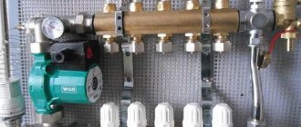
To keep the unit out of sight, you can place it in a special cabinet, which is offered to their customers by manufacturers of locking mechanisms. The body of this cabinet is made of metal. It is equipped with a door, and its side walls have holes for heating pipes. Sometimes the collector group is simply placed in a niche or on the wall, securing the combs with special clamps.
This comb is placed in a place specially equipped for it. As you can see, it looks quite aesthetically pleasing, and most importantly, access to this node will not be difficult
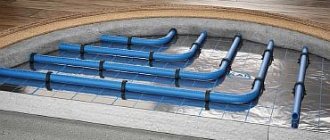
The pipes that extend from this distribution device are located in the walls or floor and are then connected to the heating radiators. If the pipes are located in the floor screed, the heating appliances should be equipped with an air vent or an air valve.
Comb cabinet
Next, the cabinet in which the unit is located is installed. The main function is to keep the distributor closed. If a built-in unit is planned, then a space for a cabinet is cut out in the wall.
Photo 2. Heating manifold cabinet for heated floors. It hides all heating equipment from view.
Purchasing a manifold cabinet will greatly simplify the installation and maintenance of the unit.
All pipes and switches are closed from prying eyes, and circulating pumps are also located there. The cabinet itself is compact, which allows it to be mounted on a wall or built in.
- External cabinets have noticeable dimensions, usually 1x2 meters, but the size can vary depending on the number of pumps and other additions.
- Built-in - located in the wall, only the door is visible from the outside. This is combined with hidden wiring and pipes running under the flooring. Overall it has an aesthetic appearance.
Installation of pumps will require electrical wiring of appropriate capacity, usually a separate cable. Electrical wiring is designed in advance taking into account the presence of electronic devices.
The best option for placing the unit is a room that will not be damaged in the event of a pipe break or leak. A living room or storage room will not work. The unit will be used for a long time, so the appearance of liquid cannot be avoided, if only because the valves are worn out. A separate room will allow you to detect problems faster.
You can calculate the dimensions of the cabinet based on the average size of the equipment: from 0.5 to 1.5 meters - this is determined during the system design process. Stages:
- First, the comb is installed and the pipes are supplied.
- The cabinet is installed in the selected location. For a built-in wardrobe, a hole in the wall is pre-prepared.
- According to the diagram, the unit is assembled, additional devices such as valves, faucets, taps, etc. are installed.
- The collector is turned on and checked.
How to build a collector yourself?
You can buy a ready-made connection, choosing one that would approximately meet the needs of your home. But achieving an exact match is quite difficult. Therefore, it is better to make a heating comb yourself. Let's figure out what is needed for this.
Planning stage
There are a number of parameters of the heating system of the house that you should know when building a unit.
- The number of circuits through which heated water will pass.
- The number and technical characteristics of the heating equipment included in the scheme.
- Additional equipment involved in installation. This refers to pressure gauges, thermometers, taps, storage tanks, valves, pumps, etc.
It is also necessary to provide for the possibility of increasing the load if over time it is necessary to build in elements that were not taken into account in advance. This could be, for example, solar panels or a heat pump.
It is necessary to foresee in advance not only the number of circuits operating in the heating system, but also additional equipment that will be included in the overall scheme
Determining the block design
The design of the future node depends on the connection point of each circuit. After all, there are some connection nuances that cannot be ignored.
- Boilers (electric and gas) must be connected to the comb from above or below.
- The circulation pump should be connected from the end of the structure.
- Solid fuel units and indirect heating boilers also need to be cut in from the end.
- The supply circuits of the heating system are connected from below or from above.
For clarity, it is necessary to make a drawing of the future compact and neat unit. This will help determine the quantity and types of materials we will need. All necessary dimensions and threaded connections with thread pitch are also applied to the drawing. All circuits should be marked to guide the drawing when connecting.
This drawing shows a four-way manifold. You may not make a drawing and will limit yourself to a sketch, but do not forget to put on it all the dimensions necessary for the work
The distance between the nozzles of both combs should be from 10 to 20 cm. These are the optimal parameters for maintenance. The distance between the supply and return combs themselves should be within the same limits.
Sequence of work
To make both combs, not only round, but also square pipes can be used. The sequence of work performed is as follows:
- In full accordance with the parameters indicated on the drawing, we purchase all the necessary materials.
- According to the drawing, we make the connection by welding pipes, taking into account their subsequent functions. Welding areas should be cleaned with a wire brush and degreased.
- Testing a homemade unit is a necessary stage of work. To do this, all pipes are hermetically sealed except one, through which hot water is poured into the system. Let's take a good look at all the joints: they shouldn't leak.
- Now the collector can be painted and dried thoroughly.
- Next, you should connect pipes, locking mechanisms and control equipment to it.
After this, the device is ready for use. This will differ favorably from purchased products in that it is built taking into account the needs of a particular home, and this is very important for its further operation. Of course, a high-quality and functional device can only be obtained if the master knows how to handle a welding machine and metalworking tools.
In order for a homemade collector block to work more efficiently than a purchased one, the master needs to be able to handle both welding equipment and plumbing tools
You can learn how to make a polypropylene manifold by watching this video:
Thermal load of the building:
kW
Attention! The software products presented do not replace the professional design necessary to obtain reliable results under specific application conditions. By using this product, you agree to the “Disclaimer” and the established Rules and accept all responsibility that may be assigned to you. Calculations are made according to the regulatory methodology in accordance with current legislation, but do not take into account special situations. The results offered are of an estimated nature.
Design and principle of operation
In the process of laying out the pipes of the heating circuits, their ends from all rooms converge in one place, where the heated floor comb is connected to them. It is a distribution and mixing unit whose task is:
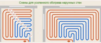
- reduce the temperature of the coolant supplied from the boiler. To supply the floor system, you need water with a temperature of no more than 45 ° C, and the heat generator rarely heats the coolant to such a low threshold. Typically, the temperature at the comb inlet is at least 55 °C;
- provide the required amount of heat for each room. Here the distribution comb works as a regulator for the release of thermal energy, controlling the coolant flow in each circuit.
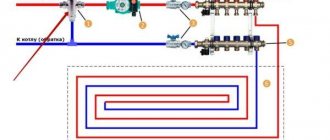
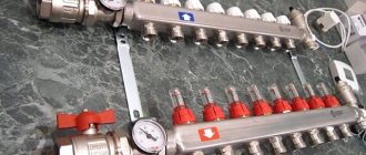
The distributor for underfloor heating visually resembles large heating combs installed in heating points. It also has 2 horizontal collectors - supply and return, to which consumers are connected, in our case - heating circuits. From the ends, coolant is supplied to the collector pipes from the main line - from the boiler room. A typical comb connection diagram is shown in the figure:
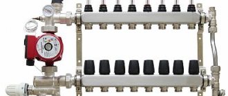
To regulate the amount of water flowing into each circuit, valves with a pressure rod are installed on one of the manifolds. Adjustment can be done either manually or using various automation tools, for example, servo drives. To control the amount of coolant, the outlets from the second collector are equipped with flow meter flasks. The comb structure is shown in detail in the diagram:
Here you can see that in addition to the elements listed above, an important part of the comb is the circulation pump. Without it, not a single circuit will be able to operate, since it is the pump installed between the two collectors that is responsible for circulating the coolant through the pipes.
Water in heated floors does not move naturally, only with forced impulse. Accordingly, in the absence of electricity, the system will not be able to function.
The very principle of operation of the comb is as follows. The hot water coming from the boiler enters all circuits in the required quantity, stimulated to move by the pump. Moreover, the coolant moves in a circle until its temperature drops below the set one. Since the water temperature is controlled by a three-way valve sensor, after it decreases, the valve will begin to open the way for water from the boiler line, mixing it with the cooled coolant.
When the temperature in the manifold rises to a predetermined limit, the three-way valve will shut off the line again. The comb pump for a warm water floor works non-stop, providing circulation within the system, independent of other heating networks in the house. To empty the unit, the comb design provides for the installation of drain valves. In order to release air from this separate system, the circuit can be supplemented with automatic air vents.
Leaders of sells
For an even clearer understanding of what a distribution comb is and how to choose the best device for yourself, you need to look at the recent sales leaders. From this information, you can find out what requirements must be met and what new functions have been added by manufacturers.
You will be presented with 2 types of distribution comb and distribution manifold, common throughout the world, which have the most modern functions:
- distribution comb for 2 pipes. Combines low price and excellent quality. The manufacturer is the famous company Rehau. The average price in Russia is 700 rubles. Serves to regulate the coolant on several circuits. You can connect to the device both ordinary cold water passing through pipes and a heated floor system, as well as other heating devices. Installation of the comb is facilitated thanks to the sliding sleeves with which it is attached to the pipes. Made of brass, this material is characterized by long service life and high strength.
- distribution manifold for 11 groups. Collectors have the same functions as combs, the only difference is in the number of connections - the collector has many more of them, connections are made in groups, for cold and hot water separately. Rehau has proven the high quality of its devices. This is evidenced by the numerous purchases by Russians of collectors and combs from their company. The Rehau Rautitan HLV distribution manifold branches out the circuits of radiator distribution systems. All devices have passed mandatory quality checks and necessary tests, including pressure testing in emergency situations. Just like the comb, the manifold of this company is made of brass, which indicates high quality and durability. The average price in Russia for the Rehau Rautitan HLV distribution manifold is 11,000 rubles. The kit includes: eurocone, ball valves, connecting nipples and built-in air valve.
This article will help you assemble a heat collector yourself:
The market of modern technologies is filled with new products every day; distribution combs and manifolds are supplemented with convenient functions for ease of use. They all have their positive, and in rare cases, negative qualities. To choose the right distribution comb or manifold for your home or apartment, you should learn as much as possible about these devices, then it will be difficult to make a mistake in your choice.
How to assemble a heated floor comb?
It must be said that assembling a comb with your own hands is a very real task. If you installed the heating system in your home yourself, then you have enough skills to assemble this unit. Moreover, factory-made combs are supplied complete and are accompanied by installation instructions with diagrams and explanations. An example of such a diagram is presented below:
Note. By agreement with the seller, the comb can be supplied assembled; you just need to indicate the number of bends for connecting the pipes. The circulation pump, three-way valve and other fittings are not included in the kit; they must be purchased separately. They are often sold as a separate unit that connects to the comb manifolds.
At the moment, distribution units are made of the following materials:
- brass;
- stainless steel;
- plastic (polyamide).
A factory-made plastic comb is truly a godsend; its cost is much lower than that of its metal “brothers.” Moreover, in practice it functions no worse; in any case, there are very few negative reviews about it. Assembling a distributor from any material consists of connecting the sections of the comb to each other, screwing a mixing unit from a pump with a valve to them, installing thermometers, taps and air vents. The finished collector can be installed in place and pipes connected to it.
For those who do not want or cannot purchase a plastic manifold, there is another option - to independently solder a comb from polypropylene pipes and fittings. To do this, you need to stock up on the required number of tees and sections of PPR pipes of the same diameter. Since tees cannot be connected directly to each other, pipe blanks should be cut to serve as connecting nipples.
Advice. A homemade polypropylene comb should not look as sloppy as in the photo shown above. To do everything beautifully, you need to carefully select the length of the nipples from the pipes, then the tees will fit tightly to each other.
If you have managed to solder the required number of tees, all that remains is to securely attach them to the wall, and then fit the rest of the piping around them: pump, valve, taps and other parts. We must try to ensure that the massive parts are attached to the wall independently, and do not load the distributor with their weight. True, a self-made comb will be devoid of flow meters and control valves, but if necessary, they can be purchased and installed additionally.
Kinds
Collectors are made of materials resistant to adverse environments:
- steel;
- copper;
- brass;
- polymer compositions.
Devices also differ in the number of branches for which they are designed. The maximum number of additional branches is 12.
They are classified according to the complexity of the system being installed. Devices with a simplified design are not designed for the installation of complex additional devices. For advanced automated systems, combs with built-in sensors, electronic control devices and reinforced fittings are produced. Installed:
- pressure and temperature sensors;
- thermostats;
- automatic coolant supply control units;
- electronic valves with fine adjustment settings (for adjusting temperature, draining liquid, and others);
- air vents;
- mixers.
How to adjust the comb?
In order for the water heated floor to provide a comfortable temperature in all rooms, the distribution unit must be pre-configured. The system is regulated according to 2 parameters of the coolant:
The first parameter is set on the three-way mixing valve. This can be done manually by setting the required water temperature by turning the adjustment wheel. But more often, the circuit involves a thermostatic head with a remote sensor and a capillary tube, so the water temperature must be set on it. The sensor is tightly attached to the manifold.
Quantitative adjustment of the comb can be done either manually or automatically. By rotating the cap on the valve of each circuit and looking at the flow meter readings, you should achieve the calculated water flow, if you know it. If not, then you will have to adjust it by feel within a few days.
Automatic adjustment involves replacing the caps of special servo drives that remotely interact with thermostats in all rooms. Then the comb with the pump will supply as much coolant to the heating circuits as is needed at the moment. Servo drives on all taps will control the flows at the command of the thermostats.
Building parameters
Enter the length and width of the building. If the roof is sloped, then the height is entered along the ridge.
| Length: | m |
| Width: | m |
| Height: | m |
Roof angle:
Roof area:
| Number of windows: | PC. |
| Window area: | m² |
| Required temperature inside the house: | ⁰C. |
| Building location: |
| average temperature | ⁰C |
| Design temperature | ⁰C |
| Heating season | days |
What you need to know about the cons?
After the advantages of using distribution combs in heating systems have become clear, it makes sense to dwell on some of the disadvantages:
- High price. Collectors are made of durable, high-quality metal, the cost of which is above average. High-precision locking equipment is also expensive. The more circuits a comb serves, the higher the cost of equipping it.
- Energy dependence. Collector heating without a circulation pump does not work. Therefore, you need to prepare for additional payments for electricity.
- High pipe consumption. The consumption of pipes in collector heating systems is several times higher than in conventional ones, since a separate loop must be pulled to each device. All this complicates and increases the cost of installation work.
The collector system, according to experts and those who already use it, is the most modern, reliable and efficient.
But at the same time, both its arrangement and operation are expensive.