Initial data
| Room length | m | Pipe laying step | cm | |
| Room width | m | Supply line length (total) | m | |
| Desired air temperature | °C | Insulation | ||
| Supply temperature | °C | Insulation thickness | cm | |
| Return temperature | °C | Screed thickness above the pipe | cm | |
| Temperature in the lower room | °C | Finish coating | ||
| Pipe | ||||
Air 0 40 Supply 0 80 Return 0 80
Calculation results
| Room area | m2 |
Materials
| Damper tape length | m |
| Pipe length | m |
| Volume of screed solution | m3 |
| Cement | kg |
| Sand | kg |
| Plasticizer | l |
| Fiber | kg |
Floor surface temperature
| 0 40 | 0 40 | 0 40 |
| Maximum floor surface temperature | Minimum floor surface temperature | Average floor surface temperature |
| °C | °C | °C |
Heat flow
| Heat flow upward | W |
| Heat flow down (heat loss) | W |
| Total heat flow | W |
| Specific heat flux upward | W/m2 |
| Specific heat flow down (specific heat loss) | W/m2 |
| Total specific heat flux | W/m2 |
Coolant
| Coolant flow | kg/s |
| Coolant speed | m/s |
| Pressure drop | bar |
Supply temperature / return temperature
Supply temperature—temperature of the coolant in the supply manifold. Those. at the entrance to the heated floor circuit.
Return temperature - the temperature of the coolant in the return manifold (at the outlet of the circuit).
In order for a warm floor to heat a room, it must give off heat, i.e. The supply temperature must be higher than the return temperature. It is optimal if the difference in supply and return temperatures is 10°C (for example, supply - 45°C, return - 35°C).
To heat the room, the supply temperature must be higher than the desired room temperature.
Up
Features of electrical floor systems
The technology for preparing and laying out electric heating elements differs from the design of water circuits and depends on the type of heating elements selected:
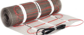
- resistive cables, carbon rods and cable mats can be laid “dry” (directly under the coating) and “wet” (under screed or tile adhesive);
- carbon infrared films shown in the photo are best used as a substrate under a coating without pouring a screed, although some manufacturers allow installation under tiles.
For reference. Self-regulating rod systems are carbon heating elements connected in parallel by two conductors. If one rod burns out, the remaining elements will increase the heating power and continue to heat the room.
Electric heating elements have 3 features:
- uniform heat transfer along the entire length;
- the heating intensity and surface temperature are controlled by a thermostat based on sensor readings;
- intolerance to overheating.
The last property is the most unpleasant. If in a section of the circuit the floors are filled with furniture without legs or stationary household appliances, heat exchange with the surrounding air will be disrupted. Cable and film systems will overheat and will not last long. All the nuances of this problem are covered in the next video:
Self-regulating rods easily tolerate such things, but another factor begins to influence here - it is irrational to buy and install expensive carbon heaters under furniture.
Length of underfloor heating supply line
This is the sum of the pipe lengths from the supply manifold to the beginning of the heated floor circuit and from the end of the circuit to the return manifold.
When placing the underfloor heating collector in the same room as the underfloor heating, the influence of the supply line is negligible. If they are located in different rooms, then the length of the supply line can be large and its hydraulic resistance can be half the resistance of the entire circuit.
Up
Selection of cable and film heaters
In connection with the above points, the calculation of electric heating is somewhat simplified; the parameters of a cable heated floor are determined as follows:
- Calculate the amount of heat needed to heat a specific room (see section one).
- Draw the layout of the room with the location of stationary furniture and household appliances. Make the drawing to scale to the actual dimensions of cabinets, washing machines, and so on.
- Calculate the free area of the room by subtracting the square footage of the occupied areas.
- The previously found amount of heat should be distributed over the remaining area. Divide the required power by the square footage of the free area - get the heat transfer from 1 m².
- Resistive cables and mats with a thermal power of 9-25 W/m. items are sold in fixed lengths. Select a heating element from the manufacturer's catalog according to the required heat transfer.
- Divide the square footage of the free section by the length of the selected product - you will find out the cable layout pitch.
Scheme of underfloor electric heating of a bathroom
An example of calculating the bathroom of a one-story house with an area of 6 m², of which 2.5 m² are occupied by a bathtub, sink and cabinet. The square footage of the free area is 3.5 m², the required thermal power is 600 W. According to the catalog of the famous Devi brand, we select a two-core heating cable of the DEVIflex 18T brand, 37 meters long with a heat output of 622 W. We divide 3.5 m² by 37 m, we get a laying step of 0.095 m, rounded - 10 cm.
Note. It is even easier to select cable mats - the manufacturer indicates the area occupied by the heating element. For the bathroom, a product with a power of 635 W of the DEVImat 200T brand, designed for an area of 3.45 square meters, is suitable.
Film heaters placed under the floor covering are calculated and selected in a similar way. A small nuance: when installing carbon film or resistive cable in living rooms, a minimum distance of 150 mm is made from the partitions. These stripes along the walls will also have to be subtracted from the total square footage. On loggias, balconies and bathrooms, this indentation is taken to be equal to the laying step (in the example - 10 cm).
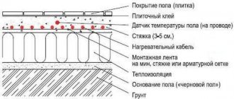
Screed thickness over underfloor heating pipes
The purpose of the screed over the pipes of heated floors is to absorb the load from people and objects in the heated room and evenly distribute the heat from the pipes over the floor surface.
The minimum permissible thickness of the screed above the pipe is 30 mm with reinforcement. With a smaller thickness, the screed will have insufficient strength. Also, the small thickness of the screed does not ensure uniform heating of the floor surface - stripes of hot floor appear above the pipe and cold between the pipes.
It is not worth pouring a screed thicker than 100 mm, because... this increases the inertia of heated floors and eliminates the possibility of quickly adjusting the floor temperature. With a large thickness, a change in the temperature of the floor surface will occur after several hours, or even days.
Based on these conditions, the optimal thickness of the heated floor screed is 60-70 mm above the pipe. Adding fiber and plasticizer to the solution allows you to reduce the thickness to 30-40 mm.
Up
Calculation rules
To install a heating system on an area of 10 square meters, the best option would be:
- use of 16 mm pipes with a length of 65 meters;
- the flow rate of the pump used in the system cannot be less than two liters per minute;
- the contours must be of equal length with a difference of no more than 20%;
- the optimal distance between pipes is 15 centimeters.
It should be taken into account that the difference between the temperature of the surface and the coolant can be about 15 °C.
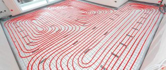
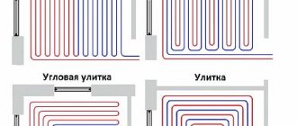
The optimal method for laying a pipe system is represented by a “snail”. It is this installation option that promotes the most uniform distribution of heat over the entire surface and minimizes hydraulic losses, which is due to smooth turns. When laying pipes in the area of external walls, the optimal step is ten centimeters. To perform high-quality and competent fastening, it is advisable to carry out preliminary markings.
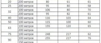
Table of heat consumption of various parts of the building
Average floor surface temperature
This parameter is the main criterion for calculating a heated floor in terms of comfort for residents. It represents the average value between the maximum and minimum floor temperature.
According to standards, in rooms with constant presence of people (living rooms, offices, etc.), the average floor temperature should not be higher than 26°C. In rooms with high humidity (bathrooms, swimming pools) or where people are not constantly present, the floor temperature can be up to 31°C.
A floor temperature of 26°C does not provide the expected comfort for the feet. In a private house, where no one has the right to tell the owner what temperature to heat the home at, you can set the average floor temperature to 29°C. At the same time, your feet will feel comfortable warmth. You should not raise the temperature above 31°C - this leads to drying out the air.
Up
Find out the required thermal power
To calculate all the parameters of a future heated floor - water or electric - it is necessary to determine how many watts of heat to supply to heat a particular room. We suggest calculating the required heating power in the simplest way - by area or volume of the room.
Advice. Installing underfloor heating circuits is not a cheap pleasure. The price of work, taking into account materials and components, ranges from 5-8 USD. e. per square meter (without installing and connecting the boiler). If you plan to hire a team of craftsmen and do not have a heating system design, require all calculations from the contractors, then compare the results.
As an example, we use the layout of a small one-story house of 100 m² (according to external measurements), shown in the drawing. Please note that corner rooms with light openings and external walls will lose much more heat in winter than internal ones - a corridor, a bathroom and a hallway. The nuance is taken into account in the proposed methodology:
- By measuring and multiplying the lengths, find out the square footage of each room.
- Multiply the area of rooms with one outer wall and a light opening by 0.1 kW. This category also includes central rooms (in the example, the hallway, bathroom and corridor).
- Heating rooms located in the corners of the building will require more thermal energy. The square footage of a room with two external walls and a window should be multiplied by 0.12 kW (kitchen and children's room).
- If there are 2 or more window openings in a corner room, the area is multiplied by 0.13 kW (living room and bedroom on the layout).
The calculation results are the required heat output of heating circuits or radiators in kilowatts separately for each room. With the obtained figures, you can proceed to the next stage of calculation.
Note. The indicated values are valid for the central zone of the Russian Federation and the Republic of Belarus. For dwellings located in the south, the thermal power values must be multiplied by a factor of 0.7. In the northern regions, an increasing factor of 1.5-2 is applied to the results.
The above method is not suitable for rooms with ceilings of 3 meters or more. In such cases, the required amount of heat is calculated by the volume of the premises, multiplied by 35, 40 or 45 W, depending on the location inside the building. The calculation of the load on the heating system is described in detail in a separate article.
Determination of heating heat transfer by volume of rooms with ceilings of 3 m and above
Calculating the circulation pump
To make the system economical, you need to select a circulation pump that provides the required pressure and optimal water flow in the circuits. Pump passports usually indicate the pressure in the circuit of the longest length and the total coolant flow in all loops.
The pressure is influenced by hydraulic losses:
∆ h = L*Q²/k1 , where
- L —contour length;
- Q - water consumption l/sec;
- k1 is a coefficient characterizing losses in the system; the indicator can be taken from hydraulic reference tables or from the equipment passport.
Knowing the pressure value, calculate the flow rate in the system:
Q = k*√H , where
k is the flow coefficient. Professionals assume the flow rate for every 10 m² of a house is within 0.3-0.4 l/s.
Among the components of a warm water floor, a special role is given to the circulation pump. Only a unit whose power is 20% higher than the actual coolant flow will be able to overcome the resistance in the pipes
The figures regarding pressure and flow rates indicated in the passport cannot be taken literally - this is the maximum, but in fact they are influenced by the length and geometry of the network. If the pressure is too high, reduce the length of the circuit or increase the diameter of the pipes.
How to calculate a water circuit
First you need to create a room heating project, determine the coating material and the temperature of the coolant (about 55 °C). To control the temperature distribution, two thermometers are installed - at the inlet and at the outlet of the coolants. A difference in readings of 5 - 10 °C indicates correct operation. Thus, the temperature of the main floor area with a properly operating heating system should not exceed 29 °C. And in bathrooms and border areas it is 35 and 33 °C, respectively.
Pipe laying
For proper installation of pipes, the following laying methods are used: snake (regular, corner or double) and snail. It will be more effective to combine several methods. For example, lay the border zone in the shape of a snake, and the central zone in a snail shape. The latter is more suitable for voluminous rooms without geometric changes, and for complex ones a snake is used.
The pipes are laid in increments calculated in the project. The laying step for boundary zones is 10 cm, and for the main ones it can vary from 15 to 30 cm, but not more than 30 cm, this is due to the sensitivity of the temperature difference on the floor area.
Next, it is necessary to take into account the following point: the smaller the laying step, the longer the length of the pipes used. You can calculate how many meters of pipe it will take per square meter of floor using the formula:
To calculate the length of pipes by area, the formula is used:
L=S/N,
where , S is the area of the insulated floor (m2), N is the laying step, L is, respectively, the required pipe length.
In practice, in the calculation of the area, you need to add a coefficient of 1.1 - the length reserve for turns, and it is also worth adding the length of the sections to the collector.
Maximum contour length
The length of the loop is directly proportional to the hydraulic resistance and pressure loss in the circuit, which are determined by the diameter of the line. It has been established that when the pressure decreases by 20 kPa (0.2 bar) from the worker, it leads to a locked loop effect. As a result, circulation of coolant through the pipes will become impossible.
In practice, the optimal length of one loop will be:
- a pipe with a diameter of 16 mm will produce a contour of no more than 100 m;
- with a diameter of 20 mm, the maximum loop length will be up to 125 m;
The permissible minimum length of the circuit can be any, but it is worth remembering that to simplify pump balancing, loops should be cut of approximately the same length.
Pump power
An important element of the system is the pump. To select it, you need to calculate how much heat removal from each square meter is obtained in accordance with the project, then you need to multiply this value by the number of square meters in the room, and we get the total value.
The power of the pump is determined by the ability to pump a volume of coolant through itself in a certain time. Now it remains to compare the total value with the power of the installed pump.
Calculation rules
In order to simplify the calculation process, you can use special calculators widely available on the Internet.
They are often available on the websites of various companies that carry out work on laying heated floors. There you can also find various tables that contain average calculations and necessary formulas. If you have any doubts about your abilities, contact professionals who have the necessary knowledge and tools at their disposal. In order for specialists to prepare a competent, accurate calculation, you will have to provide up-to-date data on the features of the layout of your premises, and it is best to show a detailed plan.
If you decide to calculate the power yourself, then you should start by drawing on a special paper a floor plan with the placement of the heating circuit and indicating the windows and doors. The scale is calculated as follows: 1 cm on paper is equal to half a meter of real area
Before you start drawing, you should pay attention to the following parameters:
- pipes should be located along walls and windows;
- the area of the room should not be more than 20 m2, otherwise it is worth dividing it into several parts and calculating a separate heating circuit for each of them;
- There must be a distance of at least 25 cm between the wall and the first turn of the circuit.
The number of pipes is calculated as follows: the total length is measured, after which it is multiplied by a scale factor. The result obtained is added to the distance of two meters (connection of the circuit to the riser). The total length is divided by the length of one pipe, since the maximum permissible pipe length should not exceed 100 m.
The diameter of the pipes depends on the distance of the structures: they cannot be located more than 50 cm from each other. A pipe laying pitch of 30 cm implies a heat transfer value of 50 W per 1 m2. The power indicator increases according to the diameter of the pipes and decreases if the laying pitch increases.
The power of a water floor is a combination of indicators of the total area of the house, pipe and floor materials, and the temperature difference between the supply and incoming coolant. The power indicator per square meter should not be more than 25% higher than the level of heat loss. If this value cannot be achieved, it is necessary to recalculate, change the diameter of the pipes and the size of the laying step.
What is a calculator for?
For heated floors, it is necessary to make accurate calculations, since the materials are high in cost, but the payback can also be seen after several months of operation. It is best to do all calculations using a special calculator. This calculation can be done directly online.
With it you can make the thermal parameters of the system, take into account the diameter and length of the pipe. The calculator will help you calculate the material, regardless of how it will be sold: using the wet method or the dry method.
Another advantage is that if the maximum permissible parameter values are too high, the calculator will generate errors.
First of all, it is worth considering that heat flows must go from bottom to top, then the conditions in the room will be favorable for humans. A warm floor will not take up much space, and all heating systems are also placed compactly.
We recommend: How to lay heated floors over wooden joists?
If underfloor heating systems are implemented correctly, they will not only heat well, but also, using high-quality materials, will last a long time. The service life can reach 75 years.
Sometimes a heated floor system is the only way to heat a room; if it is not enough, then additional sources are installed. The calculator will calculate everything exactly for a given room.
Results
Having carefully made all the calculations online, you can double-check them by calculating them yourself or asking a specialist to do it. It is important to remember that calculations are the initial stage, on which the correct installation of the entire system and its operation in the future depends.
- Related Posts
- Which rod infrared heated floor should I choose?
- How to install a water heated floor with your own hands?
- How to install a heated floor under a cork?
- How to lay a water-heated floor?
- How is the length of a heated floor pipe calculated?
- How does a flow meter for a heated floor collector work?