One way or another, you have faced the issue of saving and power of household appliances. Whether at the stage of the first repair or when replacing outdated equipment. It can be useful to calculate gas consumption or the need for it before purchasing a stove or boiler, choosing a gas meter, or its possible replacement. If you have questions about gas charges, if the search for new equipment is a matter of the next few weeks, an accurate method for determining gas consumption and formulas for calculation will make your life easier.
Gas prices are gradually rising, and appliances are becoming more powerful, so it doesn’t hurt to come up with your own strategy to optimize costs. Our article will help you with this. You cannot find out about the current level of gas consumption in your home from conversations with your neighbors; you need accurate information.
Impact on gas consumption
Gas consumption is affected by the boiler power and the quality of the mixture.
Gas consumption depends on various factors. In large houses, boilers are installed that consume more fuel mixture than units in small buildings or apartments.
Fuel consumption is affected by:
- boiler power;
- outside temperature;
- quality of the gas mixture.
Some gas distribution companies supply undrained gas mixtures into the pipeline, which contain moisture and impurities. Calorie content decreases and volume consumed increases.
Calculation of annual operating and capital costs for the industry. boiler room
Dg tech=Dch tech* Ttech
Dg tech
=139(t/hour)*6000(hour)=834000(t/year)
Dh tech
— hourly steam consumption for technological production needs
Ttech
— number of hours of heat load use for technological needs
Dg sn=Dch sn*Tr
Dg sn
=31(t/hour)*6000(hour)=186000(t/year)
Tr
— number of hours of operation of the boiler room
Dh sn
— hourly steam consumption for own needs
Dg sp=( Q h heating -
G sp*Tp*Sr*10 -3)*10 3 /(i p p - i k ) *0.98
Dh sp
=(98(Gcal/hour)-28.8(t/hour)*103(g)*4.19(KJ/kg g)*10^(-3))*10^3/(701(Kcal/kg)-50 (g)*4.19(KJ/kg g)*0.98)=177.7(t/hour)
Dg sp=Dch sp*Tr
Dg sp=177.7(t/hour)*6000(hour)=1066290(t/year)
Q h heating
— heating load of the residential village
G sp
— average hourly consumption of make-up water to replenish the heating network (t/hour)
Tp
— make-up water temperature
Wed
— heat capacity of water (KJ/kg*g)
i p p
— enthalpy of fresh water
i to
— condensate enthalpy
Dg cat=(Dg tech + Dg sn + Dg sp)0.98
Dg cat
=(834000(t/year)+ 186000(t/year)+1066290(t/year))*0.98=2044564(t/year)
Dg tech
— annual steam production for technological needs
Dg sp
— annual steam production for own needs
Dg sp
— annual steam production for network heaters
Q g cat=Dg cat*( i p p -t p c)*10 -3
Q g cat=
2044564(t/year)*( 701(Kcal/kg)-102(g)*4.19(KJ/kg g))*10^-3=559434(GJ/year)
Dg cat
— (t steam/year)
i p p, t p in
— enthalpy of fresh steam and feed water (KJ/kg)
Vgu cat=
Q g cat 29.3*KPDrez*KPDcat
Vgu cat1=
559.4(MJ/year)*10^(3)/29.3(MJ/kg)*0.97*0.84=23431.7(here/year)
Vgu cat2=
559.4(MJ/year)*10^(3)/29.3(MJ/kg)*0.97*0.84=23431.7(here/year)
Vgu cat3=
559.4(MJ/year)*10^(3)/29.3(MJ/kg)*0.97*0.914=21534.6(here/year)
Q g cat
— annual fuel productivity (GJ/year)
29.3
— calorific value of standard fuel (MJ/kg)
KPDcat
— Boiler room efficiency
Efficiency
— coefficient taking into account fuel losses in unsteady mode
Vgn cat=Vgu cat Ke
Vgn cat1=
23431.7(here/year)/0.863=27151(here/year)
Vgn cat2=
23431.7(here/year)/0.749=31284(here/year)
Vgn cat3=
21534.6(here/year)/1.19=18096(here/year)
VGU cat
— standard fuel (here/year)
Ke
— calorie equivalent (here/tnt)
Calculation of gas consumption
The power of a boiler or convector depends on the heat loss in the building. The average calculation is carried out taking into account the total area of the house.
When calculating gas consumption, heating rates per square meter are taken into account for ceiling heights of up to 3 m:
- in the southern regions 80 W/m² is taken;
- in the northern regions - up to 200 W/m².
The formulas take into account the total cubic capacity of individual rooms and premises in the building. For heating every 1 m³ of the total volume, 30 - 40 W are allocated, depending on the area.
By boiler power
Bottled and natural gas are calculated in different units.
The calculation is based on the power and heating area. The average consumption rate is 1 kW per 10 m². It should be clarified that it is not the electrical power of the boiler that is taken, but the thermal power of the equipment. Often such concepts are replaced, and the result is an incorrect calculation of gas consumption in a private home.
The volume of natural gas is measured in m³/h, and liquefied gas in kg/h. Practice shows that to obtain 1 kW of thermal power, 0.112 m³/h of the main fuel mixture is consumed.
By quadrature
Specific heat consumption is calculated using the presented formula if the difference between the outside and inside temperatures is approximately 40°C.
The ratio used is V = Q / (g K / 100), where:
- V—volume of natural gas fuel, m³;
- Q is the thermal power of the equipment, kW;
- g is the lowest calorific value of gas, usually equal to 9.2 kW/m³;
- K is the efficiency of the installation.
Depending on pressure
The amount of gas is recorded by the meter.
The volume of gas passing through the pipeline is measured by the meter, and the flow rate is calculated as the difference between the readings at the beginning and end of the journey. The measurement depends on the pressure threshold in the converging nozzle.
Rotary meters are used to measure pressures greater than 0.1 MPa, and the difference between outdoor and indoor temperatures is 50°C. The gas fuel consumption indicator is read under normal environmental conditions. In industry, proportional conditions are considered to be a pressure of 10 - 320 Pa, a temperature difference of 20 ° C and a relative air humidity of 0. Fuel consumption is expressed in m³/h.
Calculation by diameter
Calculation of the diameter of the gas pipeline is carried out before the start of construction.
The gas speed in a high-pressure gas pipeline depends on the cross-sectional area of the collector and averages 2 - 25 m/s.
The throughput is found by the formula: Q = 0.67 D² p, where:
- Q—gas consumption;
- D is the nominal flow diameter of the gas pipeline;
- p is the working pressure in the gas pipe or the absolute pressure of the mixture.
The value of the indicator is affected by outside temperature, heating of the mixture, excess pressure, atmospheric characteristics and humidity. Calculation of the diameter of the gas pipeline is done when drawing up the system design.
Taking into account heat loss
To calculate the consumption of the gas mixture, it is necessary to know the heat losses of the structure.
The formula used is Q = F (T1 – T2) (1 + Σb) n / R, where:
- Q—heat loss;
- F is the area of the insulating layer;
- T1 - outside temperature;
- T2 - internal temperature;
- Σb—sum of additional heat losses;
- n is the coefficient of arrangement of the protective layer (in special tables);
- R - resistance to heat transfer (calculated in a specific case).
Determining heat loss is a complex calculation and is carried out by specialists at the project stage. You can order the discovery of losses at any stage of operation of the building.
With and without meter
Gas consumption depends on the insulation of the walls and the climatic conditions of the region.
The device determines the gas consumption per month. Standard mixture consumption rates apply if a meter is not installed. For each region of the country, standards are set separately, but on average they are taken at the rate of 9 - 13 m³ per month per person.
The indicator is set by local governments and depends on climatic conditions. The calculation is carried out taking into account the number of owners of the premises and people actually living in the specified living space.
Functionality, pros and cons
An ultrasonic meter is a metrological device that measures the flow rate of a gaseous medium with high accuracy. At the same time, it is structurally designed in such a way that it does not create additional resistance to the measured medium.
The meters are designed for use in the oil refining and gas industries, and in everyday life. Used to count gas used in homes, administrative buildings and housing and communal services facilities.
They are equipped with programmable computing units that provide:
- Connection to data channels. This allows you to connect them to automated accounting systems;
- When measuring the amount of blue fuel consumed, the software unit corrects the data depending on the ambient temperature, bringing the values to standard.
The advantages of the device include:
- The absence of mechanical parts ensures high reliability of all meter components;
- High-tech units allow the device to be interfaced with various computer systems for collecting and transmitting data. They have analog and digital interfaces. Supports Mobdus protocols (ASCII, RTU, TCP/IP), UNIFORM, MMS, built-in Web server;
- Possibility of on-site diagnostics. Models are available that allow diagnostics to be carried out remotely;
- The meter has a high degree of reliability;
- The absence of mechanical parts made it possible to increase the turnaround time significantly;
- Resistance to vibration and shock;
- Meters can take into account flow in any direction without readjustment;
- Not sensitive to the presence of moisture in a gas environment;
- They are used not only for measuring gas flow, but also water and liquids with physical characteristics similar to water;
- Mounted on pipes of any diameter;
- No maintenance required.
In addition to their advantages, ultrasonic flowmeters have disadvantages. For example, sensitivity to flow distortions. Cannot be used in networks with acoustic noise. Lack of domestic measurement sensors. All this hinders the spread of devices.
Calculation of liquefied gas consumption
Calculating gas using propane or butane has its own characteristics, but is not particularly difficult. What matters is the density of the flammable substance, which changes with increasing or decreasing temperature and depends on the composition of the gas mixture. Only the weight of the liquefied fuel remains constant.
The volume of gas used differs in winter and summer, so it makes no sense to use m³ units to determine the consumption of liquefied gas per 1 kW of heat; kilograms are taken for designation, which do not change with the change of seasons.
Calculation for 1 kW of heat
The amount is calculated for heating the house and heating the water in the system. If you cook food using gas, this needs to be taken into account additionally.
The formula used is Q = (169.95 / 12.88) F, where:
- Q—fuel mass;
- 169.95 - annual amount of kW for heating 1 m² of a house;
- 12.88 - calorific value of propane;
- F is the quadrature of the structure.
The resulting value is multiplied by the cost of 1 kg of liquefied mixture to calculate the cost of purchasing the required quantity. The price is usually given per 1 kg and not per 1 m³, which should be taken into account.
How to take into account standards in waybills
If an enterprise uses a car only for production needs, and at the same time is not a transport organization, it can independently develop forms of waybills, keeping the required details in them.
In the case of using cars with LPG, this will be very important, since in any case gasoline is used to start the engine in such cars. In addition, the second type of fuel can be used in other cases:
- entry into the repair area;
- warming up the engine in winter;
- other emergency situations, for example, the car needs to get to a gas station, when the main fuel has run out, etc.
The waybill must display separately gasoline consumption and gas use. You can supplement the approved waybill form so that it reflects both types of fuel. To do this, the document provides additional information:
- Technical characteristics of gas equipment;
- Volume of the gas tank (along with gasoline), etc.
A self-developed waybill form must be approved by an internal local document.
Reducing gas consumption
Saving gas is directly related to reducing heat loss. Enclosing structures such as walls, ceilings, and floors in the house must be protected from the influence of cold air or soil. Automatic adjustment of the operation of heating equipment is used for the effective interaction of the external climate and the operating intensity of the gas boiler.
Insulation of walls, roofs, ceilings
You can reduce gas consumption by insulating the walls.
The outer heat-protective layer creates a barrier to cooling surfaces in order to consume the least amount of fuel.
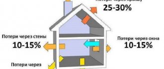
Statistics show that part of the heated air escapes through structures:
- roof - 35 - 45%;
- non-insulated window openings - 10 - 30%;
- thin walls - 25 - 45%;
- entrance doors - 5 - 15%.
Floors are protected with a material that has acceptable moisture permeability according to the norm, since when wet, the thermal insulation characteristics are lost. It is better to insulate the walls from the outside; the ceiling is insulated from the attic side.
Window replacement
Plastic windows let in less heat in winter.
Modern metal-plastic frames with double- and triple-glazed windows do not let air flow through and prevent drafts. This leads to a reduction in losses through the gaps that existed in old wooden frames. For ventilation, tilt-and-turn mechanisms are provided for the doors, which contribute to the economical consumption of internal heat.
The glass in the structures is covered with a special energy-saving film, which allows ultraviolet and infrared rays to pass through, but prevents their reverse penetration. The glass is equipped with a network of elements that heat the area to thaw snow and ice. Existing frame structures are additionally insulated with plastic film on the outside or thick curtains are used.
other methods
It is beneficial to use modern gas-fuelled condensing boilers and install an automated coordination system. Thermal heads are installed on all radiators, and a hydraulic arrow is mounted on the unit’s piping, which saves 15–20% of heat.
Detectors and temperature regulators are installed in the heating system, which regulate the boiler power depending on the state of the external climate. If the weather is warm outside, it is more efficient and economical to switch to heating with air conditioners.
Counters
What data is needed for heat accounting?
It's easy to guess:
- The flow rate of coolant passing through heating devices.
- Its temperature at the inlet and outlet of the corresponding section of the circuit.
Two types of meters are used to measure flow.
Meters with impeller
Meters intended for heating and hot water supply differ from those used for cold water only in the material of the impeller: it is more resistant to high temperatures.
The mechanism itself is the same:
- The coolant flow causes the impeller to rotate.
- It transmits rotation to the metering mechanism without direct interaction, through a permanent magnet.
Despite the simplicity of the design, the meters have a fairly low response threshold and are well protected from data tampering: any attempt to slow down the impeller with an external magnetic field will be hindered by the presence of an antimagnetic screen in the mechanism.
Meters with differential recorder
The device of the second type of meters is based on Bernoulli's law, which states that the static pressure in a flow of liquid or gas is inversely proportional to its speed.
How to use this feature of hydrodynamics to calculate coolant flow? It is enough to block his path with a retaining washer. The pressure drop across the washer will be directly proportional to the flow rate through it. By recording pressure with a pair of sensors, it is easy to calculate flow in real time.
But what if we are not talking about a closed heating circuit, but about an open system with the possibility of selecting hot water? How to record hot water consumption?
The solution is obvious: in this case, retaining washers and pressure sensors are placed on both the feeder and the . The difference in coolant flow between the threads will indicate the amount of hot water that was used for household needs.
The photo shows an electronic heat meter with pressure drop recording on the washers.
Meters for measuring fuel consumption
The meter measures the amount of gas at different conditions of temperature and pressure and, using special equipment, brings the result to the indicator that will be under standard conditions (SU) - +20 °C and 101 kPa.
The volume of fuel for the control system is determined by the formula Vс = V×(p×Tс/pс×T×K), where
- V is the volume of gas;
- p—density;
- T—thermodynamic temperature;
- K is the fuel compressibility coefficient.
Values with the letter “c” are indicators for standard conditions, without - for workers.
In everyday life, membrane, rotary and ultrasonic meters are used, in large enterprises - turbine and vortex meters - these are the most popular types of gas meters. In gas industry plants, volume is determined mainly by variable pressure changes in constrictions, often between 2 flange connections in close proximity. The meters differ in their operating features.
Diaphragm flowmeters provide minimal calculation errors and consume little electricity. The devices provide readings over a wide range, but with a low maximum pressure - up to 0.5 bar. In everyday life, the meter performs best, since the calibration interval reaches up to 10 years with high reliability of the device. The design does not respond well to mechanical gas contamination and is generally very bulky.
Rotary, or rotary, models do not depend on the electrical network; they are suitable for small industrial facilities, but they are less convenient. With a small installation area and high precision under conditions of sudden pressure changes, they make noise and more often fail. They are “afraid” of pneumatic shocks and pollution.
Ultrasonic meters are small in size and vary significantly in the complexity of their structure. Acoustic gas meters are valued for their reliability and ease of installation. Some devices contain non-volatile memory. Meters for standard sizes G1.6 and G2.5 are relatively expensive.
Turbine devices are used to measure the amount of household and aggressive gases and multicomponent compositions. Meters have become widespread at gas pipelines and chemical plants. Turbine devices record large quantities of gas at pressures up to 10 MPa and vary significantly in size and operating pressure. These are universal instruments for measuring natural gas flow in industry.
Vortex meters measure the volume of natural or inert gases. In terms of measurement range they have an advantage over other models. They detect the slightest movements in the gas mixture and determine large quantities of gas per diameter. The efficiency of a vortex flow meter is directly proportional to the fuel flow rate.
Measurement methods used in gas flow meters
Fuel consumption is calculated using direct and indirect methods.
In the case of direct gas, gas fills the measuring chambers and leaves them. The volume passed correlates with the filling-emptying cycles. Counting in membrane, rotary and drum counters works according to the described principle.
Gas meters with an indirect measurement method work with speed indicators and a known cross-sectional area. The counting method can be mechanical or other, related to the characteristics of the counter. In mechanics, turbines, impellers, and balancing elements are used.
The indirect method of calculation has other methods:
- vortex detection;
- measuring the pressure difference on the constriction device;
- calculation of heat transfer from a heated body;
- measurement of velocity pressure;
- counting based on ultrasonic movement.
The correctness of indirect methods depends on the correspondence of the speed in direction and cross-section. Flow preparation means help: turbulators, condensers and flow straighteners. The devices come separately or as elements of meters.
The devices can determine the difference in speed across the cross section simultaneously with the speed of gas movement and thus reduce the error. The latter often occurs due to fuel stagnation near the walls. Read more about direct and indirect methods for determining gas consumption below.
How is gas pressure determined?
Pressure is measured directly using pressure gauges or by adding the values of atmospheric (Pb) and excess pressure (Pi). Pb is measured at the location of the Pi converter, if the latter is in a closed space and there is pressure or vacuum in it.
The pressure tapping hole for vertical and horizontal pipes is placed radially. On a transverse pipeline it is located in the upper half of the section.
In flow meters without the specified hole, sampling is carried out in front of the meter, at a distance of 1 to 3 pipeline diameters, with a reference point from the gas meter inlet flange.