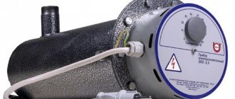
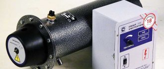
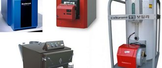
Design and principle of operation of an induction heater
A simplified induction heater consists of three components:
- alternator (1);
- inductor (2);
- core (3).
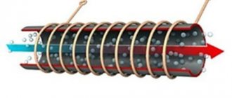
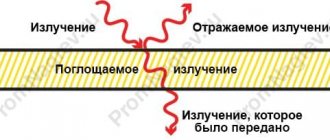
A conductive (metal, graphite) rod is placed into a coil, consisting of a certain number of turns of a conductor of a given cross-sectional area, without direct contact with it, after which voltage is applied to the coil contacts from an alternating current generator. An electromagnetic field is formed around the turns of the coil, under the influence of which Foucault eddy currents arise in the rod, heating the core. Thus, there is no heat transfer to the core; heat is generated by it independently under the influence of currents wandering in it, and can be transferred using a coolant. The temperature of the rod does not increase simultaneously throughout the entire mass, but from the surface layers to the center, depending on the thermal conductivity of the core material. At the same time, increasing the frequency of alternating current reduces the depth of inductive heating, but increases its intensity. Particularly noteworthy is the fact that the coil around the core remains practically cold during operation.
Visually this process looks like this:
Induction heating systems
Thus, an induction heating system consists, at a minimum, of a generator that converts mains power into the current necessary for operation of the installation, and an inductor that transmits energy for heating. As a rule, a resonant circuit is still needed to match the characteristics of the inductor and generator. To perform more complex tasks, a more complex system is required, including a hardening machine, a cooling system, etc.
Areas of use
*
In industry, induction heaters are used to perform the following complex processes:
- ultra-pure smelting of metals (produced in channel - non-contact induction furnaces);
- bending of large diameter steel pipes;
- performing surface hardening of steel products (construction fittings, parts of machine tool transmission mechanisms, etc.);
- heat treatment of small parts of complex configuration;
In everyday life, induction heating devices are also quite widespread. Areas of their application:
- household autonomous heating systems (for a summer house, apartment, private house);
- induction hobs and tiles for the kitchen;
- small-volume crucible furnaces for household metal smelting;
- jewelry craft.
Since the main topic of the article is an induction heater, we will dwell in detail on a heating boiler, the basis of which is the idea of inductive heating of the coolant.
Historical reminders to note
The noted melting technique is used in industry, medicine, and the domestic sphere, due to the pronounced advantages compared to traditional heating methods:
- resistive,
- fiery,
- stove and others.
Induction heating is especially useful for high-precision or repetitive applications.
Induction heating was first used by Michael Faraday, a physicist and chemist from Great Britain. The scientist discovered a unique heating property while studying the induction of currents in wires under the influence of a magnet.
However, the basic principles of induction heating were presented a little later by James Maxwell in a unified theory of electromagnetism. At the same time, James P. Joule was the first to describe the heating effect of current flowing through a conductive material.
In 1887, Sebastian Ziani de Ferranti proposed induction heating as a method for melting metals. The first fully functional induction furnace was built and introduced to the public (1891) by F. A. Kjellin. The first application of a high-frequency furnace was realized by Edwin F. Northrup (1916).
The development of solid-state oscillators using new power semiconductor technologies has provided potential beyond the industrial environment. Since the late 1980s, various proposals for use have appeared.
In recent years, there has been particular interest in induction heating for medical procedures, since this method provides accurate and targeted local heating.
Induction heater – heating boiler
Since home owners began installing autonomous heating systems in their homes, the issue of the efficiency of heating boilers remains one of the most important for them. By this indicator, at least among devices that generate heat from electricity, induction heating boilers are the leaders. Moreover, their power, which is not comparable to the identical parameter of such a device as a baseboard heater, allows the units to be used as the main method of heating in large areas.
Induction heating boilers consist of two circuits - primary (electromagnetic) and secondary (heat exchange piping). The first circuit, consisting of a voltage converter and a heat generator with an induction heater, creates an electromagnetic field, eddy currents and generates heat. The second circuit, which includes a heat exchanger with a piping system, transfers this heat through circulation of the coolant to the radiators of the heating system. Water in its pure form or with additives is used as a coolant.
In addition to the above two circuits, the heating system includes automation, which is responsible for the operation of individual components of the unit.
*
Modern induction heating boilers are installed only in a closed-type heat exchange circuit, which has a membrane-type expansion tank and a forced circulation pump in its design. The use of a circulation pump is a necessary measure and is due to the small volume of coolant at a high heating intensity of the heat exchanger. The possibility of natural circulation in such a system is excluded - without a pump, water will boil before it begins to move through the pipes.
Important! The induction boiler must be grounded. In addition, when installing a heating system, for safety reasons, the coolant distribution circuit must be mounted from plastic pipes, or the heating unit must be isolated from the steel circuit by inserting polypropylene fittings.
Induction heating boilers are classified identically to other electric heating units - according to power, design, parameters of electricity consumed. But these devices also have a classification based on the design of the electrical part.
Water boiler with transformer
To get started, get or buy an inexpensive welding inverter (transformer) with current regulation of 18-25 amperes. Small pieces of wire rod or stainless steel are used as elements for heating water in a water heater. The wire is cut into pieces of length from 3.8 to 5.5 cm (if a wire rod with a diameter of 6-8 mm is used). Then the heater body is made from a thick-walled plastic pipe with a diameter of 45-50 mm. One end of this section of pipe is covered with a fine mesh and cut wire is poured from the free open end of the body.
induction heater design diagram.
Having filled the pipe to the top with scraps, they begin to manufacture the inductor coil. Take an enameled copper wire of at least 1.5-2 mm and wind it around the made body. The number of turns varies (depending on the amperage of the welding inductor) and is 85-95. The coil is placed in the center of the body (pipes with scraps). The heater is connected to the water supply system or heating network using adapters.
To make a vortex induction boiler-water heater based on the resulting heater, you need to weld a structure resembling a donut from two pipes. This is a water heating element. Take any tank of suitable diameter and insert the inlet (in the upper part of the tank) and outlet pipes for water into it. The previously made induction coil is inserted into this housing. Then attach the heater (donut) to the nozzles so that it passes inside the inductor strictly in the center. The output ends of the coil are insulated and connected to the transformer. To prevent heat from leaving the water heater, it is covered with a heat-insulating screen.
Water, passing through the pipes inside the coil, heats up and comes out of the outlet pipe hot.
Such an induction boiler-water heater can also be connected to a system made of plastic pipes. To ensure safety, the boiler is installed at a distance of 80-90 cm from the floor and ceiling and 30-40 cm from the wall. This water heater must be equipped with a valve installed on the pipe to bleed air from the system. Such a boiler can also be used as a heater for a small room by adding a heating radiator.
Types of induction boilers
There are the following types of induction heating boilers, designated both by the principle of operation and by the manufacturer’s brand:
- SAV is a type and at the same time a trademark of new generation boilers with a power from 2.5 to 100 kW, produced by the Russian company since 2007;
- VIN - the abbreviation is not only an abbreviation for the name of a type of induction device (vortex induction heaters), but also a patented name for boilers produced by Izhevsk.
Induction heaters SAV
*
Operation of SAV units does not require the use of an inverter; a current of 50 Hz is supplied to the inductor. The electromagnetic field induced by the primary winding causes the formation of vortex flows in the secondary winding, the role of which in boilers of this type is played by a section of a closed circuit of pipes with coolant. This section of the pipe - the secondary winding - is intensively heated under the influence of Foucault currents and transfers heat to the coolant, which is forced to circulate in the heating system using a circulation pump.
The heating system is constructed using radiators or in a labyrinthine manner, reminiscent of baseboard heating, in order to increase the total area of the outer surface (heat transfer) of the pipes - the heating circuit, at a minimum, should not be minimal in length.
SAV boilers are manufactured for voltages of 220V and 380V. They use water as a coolant (pure or with antifreeze additives), as well as antifreeze. It takes about 5-20 minutes for the unit to reach full operating power (depending on the volume of coolant), the efficiency of the heaters of such devices is at least 98%. For efficient heating of a room up to 30 square meters. An induction device with a power of 2.5 kW is sufficient, the purchase of which, complete with automation and control systems, will cost approximately 30 thousand rubles.
VIN heating units
Boilers of this type are more advanced in operating principle and design, which naturally affects their cost. To operate VIN devices, an inverter is required - a device for increasing the frequency of the incoming current. High frequency current causes the formation of an electromagnetic field of high intensity, which, in turn, causes the occurrence of more powerful eddy currents in the secondary winding. In addition, the heat exchanger and boiler body are made of ferromagnetic alloys that have their own magnetic field. The result of all these processes is a high heating intensity of the heat exchanger and, naturally, the coolant.
A VIN unit with a power of 3 kW is enough to heat a room with an area of 35-40 square meters. (depending on climatic conditions and the quality of thermal insulation of external building structures).
*
Due to their greater productivity, VIN units can be used not only in residential heating systems, but also for hot water supply. To do this, additional storage tanks equipped with automatic protection are installed into the coolant circuit, the capacity of which is calculated depending on the number of hot water intake points. These containers are provided with hot water by circulating it in a system with direct-flow heating by an induction heater.
INDUCTION BOILER, INDUCTION HEATER, INDUCTION HEATER
It took almost a year to produce the results of this article, and a lot of money was spent, so please, before drawing conclusions, read from the first lines to the end - many things will become clear. It all started when the topic of replacing the heating at home came up. Gas is good, of course, but our boiler is quite old and we don’t want to change it - it has a smooth temperature control, while modern ones are discrete, i.e. they do not burn at half or 1/4 a quarter of the maximum, and the smoother the adjustment, the more economical any heater is. Yes, the savings are not big, but I can spend even 200-300 rubles in savings at my own discretion, rather than paying for gas. Well, as expected, it all started with a search engine. I entered the search query “Induction boiler” and began to study the pages found... And I had to think seriously...
First of all, I was confused by the nonsense that filled the pages describing the induction boiler, the principle of induction heating and the wretchedness of the control circuits. You can check it yourself by typing in a search engine INDUCTION BOILER WITH YOUR HANDS or INDUCTION BOILER DRAWINGS. Almost all pages contain links to a video where a man in the bathroom puts an induction stove behind the heat exchanger and happily announces that everything is ready, vilely keeping silent about the fact that the stoves have an automatic shutdown and he restarts the stove every 2-3 hours. On one of the pages promoting induction boilers, outright paranoia was stated, I can’t resist and quote: the heating element heats up because current flows through its conductor with increased resistance, so in any case it heats up to the specified 600 - 750 * C and the coolant is on its surface always boiling. Because of this, the heating element quickly becomes overgrown with scale. As a result, heat transfer decreases, and the heating element eventually burns out. In an induction boiler, you can use different coolants, even petroleum products, if they are not overheated above 70* C. WHAT??!!! 600-750 degrees?!
Okay, let's take an oil heater, throw out the thermostat and heat it up to maximum, praying beforehand that it won't burst.
Of course, it is better to see once than to hear a hundred times. SO LOOK So, the temperature of the coil is 421 degrees at a radiator temperature of 168 degrees, and this takes into account the fact that there is oil inside, and its thermal conductivity is 5 times worse than water. Where does the toga come from, interestingly, 600-750 degrees? So, just in case, the melting temperature of aluminum is 660 degrees, copper 1100. However, I know where - some nichrome alloys have a maximum operating temperature of 750 ° C, but there are great doubts whether it will be achieved. Is the heating element overgrown with scale?
And did they also tamper with the photo? Hmm...
Oho-hoyushki ho-ho... For those who don’t know, this is a heating element from a washing machine and at one time I changed them quite often, because I worked in a repair shop. So, this terrible word is SCALE: Scale is hard calcium deposits that are poorly soluble and are formed as a result of the formation of steam or heating of water. In addition to limescale, when water is heated, carbon dioxide is also formed. But its quantity matters only on an industrial scale when working with hard water. So in boiler rooms, when descaling boilers, it is necessary to ventilate the premises, but when boiling water, it is also necessary to ensure good ventilation in the room. Scale formation during heating of water always occurs if the water is hard. Only the scale may be different, because... Water hardness may not necessarily be carbonate. It is clear that the cause of the formation of carbonate scale is calcium and magnesium salts. If scale formation occurs due to calcium silicate, then the scale turns out to be sulfate. Silicic acid compounds of substances such as iron, aluminum or calcium lead to the formation of silicate scale. So, the formation of scale after working with hard water does not mean that it is carbonate scale that has fallen out. Although it should be clarified that carbonate scale is the most common. Ha! From this it is not difficult to conclude that scale is supplied only with a new portion of water, and the water in the system is changed extremely rarely and this very layer of scale is formed only once and gradually thickens with each new portion of water, and water is not added to the system often either. Consequently, the heating element of the boiler will reach the state shown in the photo in about 20 years after the aluminum radiators rot, since scale settles not only on the body of the heating element, but also on the body of the boiler itself, less, but still settles. And by the way, it is quite possible to get rid of scale in heating - 100 grams of anti-scale in the system will completely eliminate this problem - tested by operating an electric boiler for three heating seasons. But let’s return to the advertising of induction boilers: In heating element boilers, only water can be used as a coolant, and, moreover, distilled water is best. In maintenance, heating element boilers are less practical than induction boilers, because the transition contact between the power supply conductor and the conductor of the heating element itself is constantly overheated, and as a result is oxidized and weakened. It is necessary to constantly ensure that the power supply conductor does not burn out; otherwise, if it burns out, the threaded connection of the heating element may be damaged and such a working heating element will have to be replaced. This problem does not exist in induction boilers, because the connection of its heating element with the power supply is carried out through the electromagnetic field of alternating current. Well, yes, of course, of course. Is the inductor coil connected to the socket wirelessly? COOL! Most often, burnout occurs at connection points under heavy loads and continuous round-the-clock operation, so overheated contacts don’t sound convincing... Okay, what’s next? Induction boilers can be installed in any place, even not in a separate place. They are fireproof and operate silently. Yeah!!! Is the heating element inside the boiler constantly hitting the walls with its head and making it impossible to stay in the room at all? Induction boilers provide human electrical safety much higher than heating element boilers, because the heating element itself can burn out in two ways: a) with depressurization of the housing; in this case, heated nichrome crumbles when water hits it - there is no danger of a person coming under voltage; b) without depressurization of the housing; in this case, heated nichrome may stick to the body of the heating element. The heating element continues to work, and through the water the metal body of the boiler becomes energized. It is a logical argument that if the boiler is installed in violation of safety rules, any power device must be grounded. But he can kill a fool with a battery, well, if it’s with a slingshot and to the head. It is not yet possible to make the induction coil of an induction boiler with powers of 3 kW or more at 50 Hz small and compact. Therefore, the heating element boiler has much smaller dimensions at the same power than an induction boiler. It will never be possible - the frequency is low, only 50 Hz, and you need a certain inductance, and even a wire, so that it does not heat up when these same 3 kW pass through it. So an induction boiler will always be large. Well, the schematic diagrams of induction boilers are actually something. One of the sites suggested using this circuit for an induction boiler:
Actually, I smiled for quite a long time - with a power supply of 10...30 volts, are they going to heat up the boiler? Yes, the power supply for this fart will generate more heat than this toy for middle school children. Frankly, I came across one rather interesting version of a thyristor circuit, but operation at audio frequencies did not attract my attention.
One of the advertising slogans literally made me laugh: Saving on electricity consumption Consumption of 2.5 kW instead of 4–5 is an excellent result. But it turned out to be not enough for ambitious and thrifty home craftsmen. But where can I get cheap electricity for the stove? It turns out that the answer has been known for a long time. This device is called an inverter, and it converts direct current into alternating current. With its help, you can reduce current consumption for heating to almost zero. To reduce energy consumption we will need the following: Two batteries with a capacity of at least 190 Ah (preferably 250 Ah). 4 kW inverter. Battery charger (24 V). The main pipes must be made of non-magnetic material (plastic, aluminum, copper). We connect the batteries in parallel and put them on constant “charging”. The process that occurs in the electrical circuit: A direct current is generated in the batteries, which is supplied to the inverter. The inverter converts direct current into alternating current 220 V. The current from the inverter is supplied to the induction furnace, which operates in normal mode (consumption). The charger continuously recharges the batteries. Honestly, this is a quote from the Internet and I can’t even imagine who it’s aimed at. In general, the advertising of the induction boiler was disappointing, but there was still confusion - the manufacturers claimed during the interruption that the induction boiler has much greater productivity compared to the heating element. I fell for this hook - the performance of the boiler is, in fact, quite good savings in terms of light. I didn’t have the determination to make an induction boiler right away, so I decided to try first assembling an induction heating radiator. The first thing that was asked for was an induction stove, but there was no agreement with the toad on the topic of purchasing it, so having found a diagram of an induction stove on the Internet, the power part was isolated from it, which was assembled.
The circuit turned out to be quite capricious, not after the death of several IGBT transistors I decided that such experiments could leave me without my pants, fortunately I took the transistors from disassembly, so I was not too grief-stricken. I bought it HERE. I immediately ordered IRFPS37N50 from the same seller, as if I sensed something bad. And delivery in this option was relatively inexpensive - two orders, and one delivery fee. In general, having played enough with single-ended devices, I came to the conclusion that the thing is good, but the slightest error during adjustment kills the power transistors. Therefore, I decided to take a different route - try to assemble a push-pull circuit for an induction heater, since powerful field workers were already on hand. After a little thought, I decided to use the IR2153 half-bridge driver, and so that it would not be killed by heavy gates, I powered it with 1.5 A emitter followers. The result was the following circuit:
CIRCUIT DIAGRAM AND PRINTED BOARD DRAWING
The idea was quite simple - film capacitors do not hold high currents very well, so use several of them, and if there are several of them, then it will be possible to select the capacitance in such a way that the resulting LC circuit is driven into resonance and maximum magnetic fields are obtained. It was decided to use a square pipe as a heat exchanger - a heat exchange area both outside and inside, and this naturally only works to its advantage.
There were suspicions that the electronics would get very hot, since the single-cycle version had to use radiator airflow. Well, so that the air flow would not be wasted in vain, it was decided to use it as a convection flow - through a pipe to direct it inside the square pipe of the heat exchanger, thereby increasing the performance of the structure.
The location of the coils between the heat transfer registers completely shields them, which does not allow high-frequency electromagnetic radiation to escape the load, because this is not only harmful, but also reduces the efficiency of this device. Well, so that in case of damage to the insulation of the wire itself, the coils do not touch the heat exchanger, corrugated cardboard impregnated with epoxy glue was used. It was possible to use fiberglass, but I didn’t have such a large piece on hand. You can also secure the coils with sealant; in principle, the main thing is that they hold fairly tightly even if the heater falls. Although, of course, if such a thing would be dropped, if only during transportation - it turned out to be a heavy toy, but you couldn’t carry it on yourself, so there was no thought at all about the weight. High-temperature cambrics were put on the ends of the coils - not heat shrink, but fiberglass, it is much more expensive than heat shrink and looks like material. Of course, round coils have a higher quality factor, but I needed to position the coil in such a way that it would heat the ENTIRE area of the heat exchanger. That is why two rectangular coils were made. Two, because it was possible to connect them either in series or in parallel, and this expanded the probability of hitting resonance - I had no idea what kind of inductance would turn out in the end. A drawing was made, printed on paper, taped to a sheet of chipboard, holes were drilled in the corners into which nails were inserted. The studs were pre-loaded with pieces of heat-shrink tubing and the coils were wound on this template. After winding, the coils were dipped in epoxy glue and heated with a hairdryer to better impregnate the stranded wire bundles with which the coils were wound. A wire with a diameter of 0.35 mm was used; there were 28 cores in the bundle. Later I made more coils and washed them with sealant - they turned out too runny, although they held up pretty well.
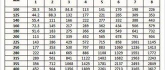
Then all this was collected into one device and adjusted. As it turned out, unlike the single-cycle version, the power transistors with the same radiator did not need airflow, but the fan was still left in - heat exchange is much better with it. However, the speed was reduced to a minimum of audibility - so it will have more resources, it will drive less dust inside, and the buzzing will not irritate. After assembly, naturally, it was necessary to compare which is actually more profitable - the oil pan or the induction cooker. A whole bunch of measurements were carried out, but each time the inductor turned out to be the winner in relation to the carnival, which quite infuriated the viewers from YouTube. Yes, of course, some measurements were not entirely correct, but the last episode practically did not provoke criticism, although opinions that I did not go to school and do not know the conservation law still flashed. Yes, I actually did not encroach on this law - we are talking about productivity and nothing more. In general, the latest measurements have been compiled into a table, based on the results of which you can draw your own conclusions about what is more profitable.
| HEATING A SMALL ROOM TO A TEMPERATURE OF 40°C | |||
| kW used up | Average wind speed | Average temperature outside | |
| Oil heater | 7 kW | 7.2 m/s | 17.7°C |
| Induction heater | 5.5 kW | 7.9 m/s | 16.3°C |
| MAINTAINING THE TEMPERATURE IN THE SAME ROOM DURING THE DAY, EVERYONE HAS ABOUT THE SAME POWER | |||
| Induction | 13.3 kW | 13.3 m/s | 15.1°C |
| Buttered | 16.5 kW | 4.5 m/s | 15.0°С |
| Convection | 13 kW | 2.7 m/s | 16.5°C |
| Two Maslenitsa | 14.8 kW | 3.7 m/s | 17.8°C |
| MORE DETAILS ABOUT THE WEATHER DATA FROM THE FORECAST SITE | |||
Full details of what was done and how it was done are shown in the video. It is shown in VERY detail, so it is more than an hour and a half, so stock up on popcorn.
Questions like “Could you assemble a control board for me?” immediately began to appear. Yes, of course I could, but there are just two drawbacks: It’s expensive because you have to make the boards manually, COMPLETELY manually, since I don’t see a queue for this device and I don’t need to order boards from the factory with a minimum batch of 10 pieces. And making a board involves ironing, hand drilling, and tinning, i.e. quite a lot of time that I can’t just take and give away - you know, life is limited and spending it on something that is not interesting to me and without taking money for it is simply stupid. The likelihood of an untrained solderer completing this design is not very high, since in addition to the board, an inductor is also required, and these are coils, the number of turns in which directly depends on the method of their connection, the thickness of the steel and the distance between the coil and the steel. In general, I decided to save myself from empty chatter on this topic and made a video with recommendations on making inductors, and if anyone wants to buy a board, I simply send them to watch this video with the question “Can you do the same?” The rows of buyers melt like snow during the rain...
The result of the competition between the induction boiler and the oil boiler was, of course, impressive and the idea of assembling an induction boiler stuck VERY tightly in my head. The first thing that needed to be decided was which inductor to assemble. Of course, unlike domestic induction boilers, I was not going to make it at 50 Hz. And for this, more serious capacitors were already needed - there are too many photos of exploding film capacitors on the Internet. That is why capacitors were ordered for induction cookers - they will definitely withstand both current and voltage. To suppress impulse noise in the power supply, capacitors were ordered and MKP series capacitors, which are used in induction cookers, were purchased to create resonance. For power supply I took 5 µF and 3 µF, for the inductor 0.27 µF. Where I bought there was already a sign that the product was not available, so choose MKP CAPACITORS yourself. Another factor for the creation of an induction boiler was their mass production, although not ours, but a more compact and high-frequency one - Chinese induction boilers with a power of 6 kW and 10 kW. True, it was clear from the photos that the Chinese were limited to a maximum power of 3 kW from one heater section, since they used single-cycle converters - this can be seen from the presence of two and three identical control boards with forced ventilation. Using a push-pull bridge inverter, I expected to get 4-5 kW from one section, and given that the power section can serve 2 sections of the inductor, there were no problems with power at all. Why is the power of an induction boiler limited? Everything is quite banal - to obtain resonance, a certain inductance is required. If the resonance is at audio frequencies, then both the control and the inductor itself will become audible, and this will be VERY tiring, to put it mildly. If we go to higher frequencies, then we will be forced to reduce the number of turns, and the strength of the magnetic field necessary for the occurrence of Foucault currents, i.e. eddy currents, which heat the steel, will decrease. After all, the strength of the magnetic field is directly proportional to the number of turns and the current flowing through them. Winding a step-up transformer to obtain more voltage did not work out for two reasons: Dimensions and cost of ferrite Problems with insulation of the inductor and the power part of the control Yes, yes, insulation here is also of no small importance - with resonance and a bridge inverter, about 800 volts are applied to the inductor coil. If you double the frequency, you will also have to reduce the number of turns by 2 times, and to obtain the same power you will have to double the applied voltage, and this is already 1600 volts. No, I didn’t dare to try this, and I don’t advise you either - this thing is becoming too dangerous. The first version of the control scheme made it clear that in addition to increased accuracy, the scheme needed to be slightly changed, which was done. However, I managed to check something in the first version:
I wasn’t impressed at all... However, after thinking a little, I came to the conclusion that I was in a hurry with the test - the magnetic field around the inductor coil was not closed, and this led to losses - the steel sheet that was located next to the boiler became noticeably heated during the experiment. Well, since I still lost control of the induction boiler, it was decided to assemble an indestructible stand for testing inductors, and, in fact, a new, more thoughtful control for the induction boiler. After sitting for an evening, I ended up with this diagram of the testing stand. In principle, the only non-traditional thing here is the first stage of current limitation - the effective value is formed not by the duration of the pulses, as is usually customary in the TL494 controller, but by changing the conversion frequency. This solution is primarily due to the fact that there is no need to deal with self-induction pulses, which cause heating of power transistors, and since the load has a reactance that increases with the frequency used, there was no doubt about the operability of this circuit solution. In addition, an analog frequency meter was introduced into the circuit, allowing you to navigate the frequencies used. Of course, the frequency meter scale was calibrated according to the readings of a real frequency meter.
CIRCUIT DIAGRAM AND DRAWING OF THE PRINTED BOARD OF THE STAND
The boiler control also underwent some changes and the final circuit diagram took on the following form:
CIRCUIT DIAGRAM AND DRAWING OF THE PRINTED BOILER CONTROL BOARD
The circuits have a general principle for controlling the current flowing through the load - frequency regulation. In the stand, the frequency depends on the current flowing through the load, but for the boiler this dependence is formed by the thermostat. Moreover, the adjustment has two stages - the first reduction in consumption occurs when the coolant temperature reaches a certain value and is carried out in steps. The second stage of regulation is smooth and changes the power supplied to the boiler inductor depending on the temperature of the heated room. Thus, the inertia of the heater is completely absent. After an unsuccessful test of the first version of the induction boiler, shielding of the coils with ferrite rods was tested - the performance increase was pronounced. This, of course, inspired me, but not much - the project was becoming too expensive - a lot of ferrite was required, but it is not cheap. The solution to the problem came in two stages. At first it was decided to use a toroidal heat exchanger with a labyrinth inside, but after a little reflection, a sketch of a toroidal induction boiler without a labyrinth and with a different arrangement of inlet and outlet pipes appeared. The first turn-on showed that there were too few turns on the boiler and the coil had to be sealed and re-wound. There was essentially a week left before assembling the control board for the induction boiler, but my hands were itching - the boiler was already ready and the readiness of the test bench also gave me no rest. A heating model with several options for electric boilers was assembled and tested, but the final experiment was disrupted - the diameter of the pipes turned out to be too small and the water in the boiler with heating element simply boiled:
The heating model was redone - a circulation pump was added, which will prevent water from boiling, and the volume of water in the model increased from one and a half buckets to six and a half, which made it possible to significantly increase the duration of the experiment. So, the hour of X, or the moment of truth has come:
To be honest, I was upset. There was no magical performance increase. It is clear that with self-circulation the probability of an increase would most likely be - with the slow movement of water, bubbles form on the surface of the heating element, which are carried away into the expansion tank, carrying away heat, but when using a circulation pump this effect is negated - the heating element is washed too intensively with water and gas formation is reduced tenfold. Of course, the induction boiler was driven into resonance, but the dependence of the flowing current is linear - it begins to increase as the frequency increases and approaches resonance, and after passing it, the current also decreases linearly. No surges of current flowing through the coil were detected. Well, since the model is fully assembled, I couldn’t resist trying to play around with the electrode boiler:
For these experiments, a new, modern electric meter was also purchased, which, after completing the measurements, simply turned out to be unnecessary. Of course, my curious nose was stuck into it too:
In general, I did not completely assemble the boiler control board - there is no difference in the heat output of an induction boiler and a boiler using heating elements, therefore I will not need this board. No, I won’t disassemble it completely yet - I have both TL494 and IR2110 in stock, but I haven’t soldered the power transistors to it yet. Let him lie around for now. But I will take into account the ideas of induction heating - with such a set of power devices you can slowly or quickly heat a lot of steel objects for various purposes. So experience was gained and the stand remained for further experiments. Of course, it’s a pity that the idea with an induction boiler turned out to be untenable, but there is a technology for manufacturing induction heaters, which are electronically more complex than factory convection heaters, but using more accurate temperature control, or using continuous control, as in a boiler, you can achieve decent savings. Let me remind you once again - we are not talking about efficiency, but about productivity, and there is no need to wave textbooks on physics and thermodynamics in my face - the experiments described in the textbooks were carried out in ideal conditions, and a home will never be in such conditions, it always has heat exchange with the environment. I didn’t have enough intelligence to calculate mathematically what and how would happen, so I put together several models and checked everything EXPERIMENTALLY and saw everything with my own eyes. So stop your sarcasm and if you have doubts, you can repeat everything - all the circuit diagrams, all the designs used are described in sufficient detail.
In conclusion, a few words about the prospects of this heating method in everyday life. Any magnetic metal can be heated. Why you will do this is none of my business. On my part, two options were successfully tested - a household iron with a steel base and a homemade soldering iron for plastic pipes. Unfortunately, at that time the inductors and power section were tested, and the temperature was controlled using a thermocouple. Today, control of this heater through an MK without the use of contact sensors has already been developed.
The operating principle is based on a gradual decrease in power supplied to the inductor as the set temperature is reached. When using IR2155o as a master oscillator, you will need an LED-photoresistor optocoupler or a photoresistor lamp. As the temperature approaches the set temperature, the LEDs light up one by one. The first increases the frequency of the master oscillator by 1.5 times, thereby moving the inductor away from resonance. The second one further increases the frequency by 1.5 times. Well, the third completely stops the generator. How to make such an optocoupler is shown in the video:
At the end of this video there is an iron test. The schematic diagram of a non-contact thermostat is shown below. The MK can be powered from any stabilized five-volt power supply. By the way, Ali sells UNIVERSAL POWER SUPPLY units that have an output voltage of 5 volts for the controller and 12 volts, which can be used to power the IR2155 and get rid of 2 W resistors. Only it is better to separate the five-volt ground from the twelve volt ground.
The circuit, board and firmware for the MK are in the ARCHIVE.
When using TL494 or SG3525 optocouplers as a master oscillator, you can use an LED-phototransistor optocoupler (PC817), the transistor of which is connected to the frequency-setting resistor circuit. Site administration address
Evaluation of marketing characteristics-statements
Many advantages are attributed to induction heating boilers, often without argument. Let us list these characteristics and evaluate the degree of correspondence of the statements to the fact:
Economical
Statement
Electricity consumption by induction boilers is 20-30% less than other electric heaters.
Fact
All heating electrical devices that do not perform mechanical work convert 100% of the energy of electric current into heat; their efficiency is always below 100%, but differs in value for different devices under different conditions. To generate 1 kW of thermal energy, it is necessary to consume more than 1 kW of electricity, but how much more depends on the parameters of the dissipation medium. Inside the boiler, of course, there are also losses - for example, for heating the coil, since any conductor material has resistance, but all these losses remain indoors
Important! Old-style meters (bakelite) will record less (1.6 - 1.8 times) electricity consumption than modern electronic ones, since they are not designed to take into account the reactive power of induction boilers.
Perhaps this fact explains the statement about the efficiency of induction boilers.
Durability
Statement
High reliability and long service life of the equipment - more than 25 years.
Fact
Indeed, the absence of moving parts eliminates mechanical wear of induction boilers. But the heating system with a VIN unit includes a circulation pump, the resource of which is much more modest. In addition, the control and automation system includes mechanisms that also consist of many components that are subject to wear.
The core of an induction heater operates under conditions of constant cyclic heating and cooling, temperature deformations, which are also a negative factor. Therefore, calling the resource of induction boilers almost limitless is an exaggeration. However, it is indeed several times higher than heating element heaters.
Consistency of characteristics over the entire service life
Statement
The absence of scale formation on the inner surface of the pipes ensures the constant efficiency of the heater and heat exchanger.
Fact
Scale is the deposition of salts contained in water (coolant). The amount of these impurities in a limited volume of coolant is also limited and small, so the effect of scale on the efficiency of the heater is insignificant. And in an induction boiler, the secondary winding is under almost constant vibration, and scale formation does not occur at all. So the statement is correct, only its significance is exaggerated.
Silence
Statement
The operation of induction heating boilers is silent, which distinguishes them from other electric heaters.
Fact
The statement is true, but all electric boilers do not make noise during operation, since acoustic waves are not included in their oscillation range. Only the circulation pump can make noise, but if you wish, you can choose a silent model.
Compactness
Statement
Induction boilers are compact, which is convenient when choosing their installation location.
Fact
This is true if you do not use a cascade of induction boilers and do not install intermediate tanks if there are several hot water intake points in the hot water supply system, since an induction heater is, by and large, a small piece of pipe with a winding.
Safety
Statement
The safety of the device is absolute.
Fact
There are no absolutely safe electric heaters. When operating induction devices, the possibility of coolant leakage from the system cannot be ruled out, and the electromagnetic field generator will continue to operate, and the system of empty pipes will heat up. To prevent the occurrence of such a situation, the boiler design provides an automatic shutdown device, but it can also fail.
Therefore, induction heaters, while outperforming their competitors in some safety criteria, are not completely safe.
Advantages and disadvantages of the device
The liquid can be machine oil or antifreeze.
Induction heating can provide a number of benefits that the use of electrode devices cannot provide. Since the liquid is heated by a metal element that does not take part in electrochemical reactions, the durability of the device depends only on the coil. The duration of its operation is determined by the duration of operation of the device. Some inductors remain operational for more than 10 years. This also relates to the compatibility of the unit with different types of coolant fluids. In addition to plain water, machine oils and antifreeze compounds are suitable for this role.
The internal parts of the unit are not covered with scale deposits during use. Due to constant contact with liquid, the likelihood of parts overheating is reduced, which also helps to extend the service life. Convection in the device usually reaches a sufficient level that it is not necessary to install a circulation pump. There is no need for soundproofing measures - the device operates quite quietly.
For an emergency shutdown of a homemade device, a temperature sensor is required.
However, the induction heater also has its weaknesses:
- The device requires electrical energy to operate. In a room where there is no electricity or where it is not possible to provide access to it, the boiler will not be able to operate. In places with regular network outages, it will not work effectively.
- When the temperature rises excessively, the heat-transferring liquid turns into a gaseous state. This provokes a strong increase in pressure in the structure, which can result in pipe rupture. To prevent this from happening, it will be necessary to equip the installation with means of monitoring pressure and temperature. This could be a pressure gauge, a temperature sensor, or a device for emergency shutdown when the parameters go beyond the specified range.
The need for additional equipment can contribute to a significant increase in the cost of equipment for a homemade induction heater.
The device is considered almost completely silent, but in practice this is not always the case. This applies to industrial production models and home-designed installations.
Disadvantages of induction heaters
- High cost of devices.
- Considerable weight yet compact.
- The presence of a factor influencing the electromagnetic field on the body and devices.
Let's look at the last point in more detail.
The electromagnetic field affects living organisms in much the same way as food in a microwave oven - it heats them to a certain depth, and this can have consequences. The intensity of the field's influence, including on a person, is determined by such an indicator as the energy flux density (EFD), which increases with increasing frequency of the current supplied to the primary winding. When operating induction heaters, it is necessary to comply with the sanitary norm of the limit value of PPE, which is established in SanPiN 2.2.4/2.1.8.055-96, depends on the duration of exposure to the field and is, for example, for an 8-hour exposure - 25 μW/sq.cm, one-hour – 200 µW/sq.cm.
In addition, the inductor radiation negatively affects electronics and radio equipment located nearby, creating interference during operation.
Important! To protect yourself from the effects of electromagnetic fields, you can surround the boiler with a fine-mesh (1x1, 2x2 mm) metal mesh (Faraday cage), which is not in contact with the boiler body and is grounded.
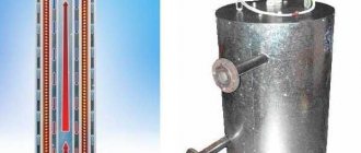
For a regular crucible
Construction of a crucible induction furnace
The residual capacity irritated metallurgists - the alloys they melted were expensive. Therefore, as soon as sufficiently powerful radio tubes appeared in the 20s of the last century, an idea was immediately born: throw a magnetic circuit onto (we will not repeat the professional idioms of tough men), and put an ordinary crucible directly into the inductor, see fig.
You can’t do this at an industrial frequency; a low-frequency magnetic field without a magnetic circuit concentrating it will spread out (this is the so-called stray field) and give off its energy anywhere, but not into the melt. The stray field can be compensated by increasing the frequency to a high one: if the diameter of the inductor is commensurate with the wavelength of the operating frequency, and the entire system is in electromagnetic resonance, then up to 75% or more of the energy of its electromagnetic field will be concentrated inside the “heartless” coil. The efficiency will be corresponding.
However, already in the laboratories it became clear that the authors of the idea overlooked an obvious circumstance: the melt in the inductor, although diamagnetic, is electrically conductive, due to its own magnetic field from eddy currents, it changes the inductance of the heating coil. The initial frequency had to be set under the cold charge and changed as it melted. Moreover, the range is greater, the larger the workpiece: if for 200 g of steel you can get by with a range of 2-30 MHz, then for a blank the size of a railway tank, the initial frequency will be about 30-40 Hz, and the operating frequency will be up to several kHz.
It is difficult to make suitable automation on lamps; to “pull” the frequency behind the blank requires a highly qualified operator. In addition, the stray field manifests itself most strongly at low frequencies. The melt, which in such a furnace is also the core of the coil, to some extent collects a magnetic field near it, but still, to obtain acceptable efficiency it was necessary to surround the entire furnace with a powerful ferromagnetic screen.
Nevertheless, due to their outstanding advantages and unique qualities (see below), crucible induction furnaces are widely used both in industry and by home-made people. Therefore, let’s take a closer look at how to properly make one with your own hands.
Operating rules
The safe operation of induction heating boilers, like any other technical devices, is ensured by following a number of rules regarding both their installation and use after installation:
- Boiler grounding is mandatory.
- The distance from the device to the walls on the sides must be at least 30 cm, from the bottom point of the boiler to the floor - 80 cm, from its top point to the ceiling - 80 cm.
- Induction boilers are installed only in a closed circuit with a membrane-type expansion tank.
- The system must include a block of safety devices (pressure gauge, air valve, overpressure relief valve, automatic shutdown system for overheating).
Device with nichrome spiral
Device with nichrome spiral
So, to smelt large volumes of metal you will need a furnace with nichrome wire. The operating principle of the design is quite simple: electric current is supplied to a nichrome spiral, which heats up and melts the metal. There are a lot of different formulas on the Internet for calculating the length of a wire, but they are all, in principle, the same.
Step 1. For the spiral, nichrome ø0.3 mm with a length of about 11 m is used.
Step 2. The wire must be wound. To do this, you will need a straight copper tube ø5 mm - the spiral is wound on it.
Frame
Step 3. A small ceramic pipe ø1.6 cm and 15 cm long is used as a crucible. One end of the pipe is plugged with asbestos thread - this way the molten metal will not flow out.
Pipe
Step 4. After checking the functionality, the spiral is laid around the pipe. In this case, the same asbestos thread is placed between the turns - it will prevent short circuits and limit the access of oxygen.
Step 5. The finished coil is placed in a high power lamp socket. Such cartridges are usually ceramic and have the required size.
Finished design
Advantages of this design:
- high productivity (up to 30 g per pass);
- fast heating (about five minutes) and long cooling;
- ease of use - it is convenient to pour metal into molds;
- prompt replacement of the spiral in case of burnout.
But there are, of course, disadvantages:
- nichrome burns out, especially if the spiral is poorly insulated;
- insecurity - the device is connected to a 220 V power supply.
Review of famous manufacturers
*
- Edison - induction heaters with a power from 4.7 to 500 kW, produced by Novosibirsk, for domestic and industrial needs;
- Miratron is a product of the Russian manufacturer of induction heating equipment NPK Miratron for domestic use, characterized by an advanced design that allows the use of the equipment without damaging the interior of the room;
- Teco-House are induction heating boilers with a unique control system, produced by the Ukrainian company of the same name according to EU and Russian Federation standards.
Manufacturing instructions
Blueprints
Figure 1. Electrical circuit of an induction heater
Figure 2. Device.
Figure 3. Schematic of a simple induction heater
To make a stove you will need the following materials and tools:
- soldering iron;
- solder;
- textolite board.
- mini drill.
- radioelements.
- thermal paste.
- chemical reagents for etching the board.
Additional materials and their features:
- To make a coil that will emit the alternating magnetic field necessary for heating, it is necessary to prepare a piece of copper tube with a diameter of 8 mm and a length of 800 mm.
- Powerful power transistors are the most expensive part of a homemade induction installation. To install the frequency generator circuit, you need to prepare 2 such elements. Transistors of the following brands are suitable for these purposes: IRFP-150; IRFP-260; IRFP-460. When manufacturing the circuit, 2 identical of the listed field-effect transistors are used.
- To manufacture an oscillating circuit, you will need ceramic capacitors with a capacity of 0.1 mF and an operating voltage of 1600 V. In order for high-power alternating current to form in the coil, 7 such capacitors will be required.
- When operating such an induction device, field-effect transistors will become very hot and if aluminum alloy radiators are not attached to them, then after just a few seconds of operation at maximum power, these elements will fail. Transistors should be placed on heat sinks through a thin layer of thermal paste, otherwise the effectiveness of such cooling will be minimal.
- Diodes used in an induction heater must be ultra-fast. The most suitable diodes for this circuit are: MUR-460; UF-4007; HER – 307.
- Resistors used in circuit 3: 10 kOhm with a power of 0.25 W - 2 pcs. and 440 Ohm power - 2 W. Zener diodes: 2 pcs. with an operating voltage of 15 V. The power of the zener diodes must be at least 2 W. A choke for connecting to the power terminals of the coil is used with induction.
- To power the entire device you will need a power supply with a power of up to 500 W. and voltage 12 - 40 V. This device can be powered from a car battery, but it will not be possible to obtain the highest power readings at this voltage.
The manufacturing process of the electronic generator and coil itself takes a little time and is carried out in the following sequence:
- A spiral with a diameter of 4 cm is made from a copper pipe. To make a spiral, the copper tube should be screwed onto a rod with a flat surface with a diameter of 4 cm. The spiral should have 7 turns, which should not touch. Fastening rings are soldered to the 2 ends of the tube for connection to the transistor radiators.
- The printed circuit board is made according to the diagram. If it is possible to install polypropylene capacitors, then due to the fact that such elements have minimal losses and stable operation at large amplitudes of voltage fluctuations, the device will operate much more stable. The capacitors in the circuit are installed in parallel to form an oscillating circuit with a copper coil.
- Heating of the metal occurs inside the coil after the circuit is connected to the power supply or battery. When heating the metal, it is necessary to ensure that there is no short circuit in the spring windings. If you touch 2 turns of the coil at the same time with heated metal, the transistors will fail instantly.
Selecting the number and type of burners
To choose the right induction hob, you need to consider the number and type of heating zones. On the modern market there are models with from 2 to 6 burners. You can choose built-in domino system appliances or compact portable stoves.
The number of burners depends on the size of the kitchen and the number of people in the family. It is optimal to choose panels with 3-4 heating zones. You can cook the first and second courses on them at the same time. For larger families, 6-burner hobs are available. But you need to keep in mind that such models take up a lot of space, so they are suitable for spacious kitchens.
The diameter of the cookware that will be used for cooking depends on the size of the burners. Panels with a heating zone from 14 to 26 cm are considered standard. Many housewives choose equipment with different burner sizes, which allows them to simultaneously cook dishes in different containers.