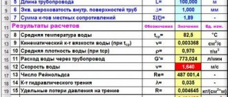
Hydraulic calculation of pipelines allows you to calculate water flow (throughput), the length of the section, its internal cross-section and pressure drop, and compare with the recommended parameters:
- Losses per 1 m of area, based on the material, are 80 - 250 Pa/m or 8 - 25 mm of water column.
- The maximum water speed for internal diameters varies: 1.5 cm - 0.3 m/s, 2 cm - 0.65 m/s, 2.5 cm - 0.8 m/s, 3.2 cm - 1 m/s s, for other parameters it is limited to 1.5 m/s.
- In fire-fighting pipelines, the maximum speed of water movement is 5 m/s.
Conditional permeability DN
The conditional permeability parameter DN (nominal diameter) is a dimensionless quantity; its numerical value approximately corresponds to the internal cross-section of the pipes (for example, DN 125). The numerical values of the conditional transition are selected to increase the throughput of the pipeline network within the range of 60 - 100% when moving from one conditional throughput to the next.
According to GOST 28338-89, the parameters of conditional cross-country ability (Dn in the past) are selected from the size range:
The values are selected taking into account the elimination of problems regarding the fitting of parts to each other. The nominal diameter based on the parameters of the internal section is selected based on the clear diameter of the pipe.
How to calculate
First of all, we determine the initial data that is needed to complete it:
- Wall thickness of water pipes.
- Internal bore diameter.
- Nominal size of conductive elements.
- The nominal diameter of the pipeline.
The length of the water supply network and the water pressure inside the system are also taken into account. It should be noted that the parameters for hot water supply and heating differ from those for cold water supply. The main directions of water consumption in a country house take into account the satisfaction of all the needs of the residents. In this case, the calculation should take into account peak loads on the water supply system, when cooking, washing by machine, watering the garden and other liquid consumption occur simultaneously. It is for such conditions that the diameter of the water supply pipe is calculated, otherwise there may not be enough life-giving moisture. Based on long-term observations of water consumption, its consumption was established at 3 cubic meters per hour. The size of a water supply pipe can be calculated based on the following ratio: Q – fluid flow, liters/sec, its value is 0.34; V – fluid flow velocity, m/sec, maximum value is 1.5; S – cross-sectional area of the pipe, m/sec.
Armed with a school calculator, we make several transformations and get the result: the internal bore diameter must be at least 18 millimeters. This is the result of the calculation; it must be rounded to the nearest standard nominal diameter (DN), which is 20 mm. However, there is a simpler technique in which there is no need to use a calculator for any calculations. This is a simple selection from a table of values:
| The nominal diameter of the pipeline, mm | Flow rate, liter/sec |
| 10 | 0,121 |
| 15 | 0,358 |
| 20 | 0,715 |
| 25 | 1,45 |
| 32 | 2,35 |
| 40 | 3,55 |
| 50 | 6,2 |
When using the table data, it should be understood that the nominal diameter is approximately equal to the internal diameter of the water and gas pipe according to GOST 3262-80. For plastic pipes, this indicator is equal to the outer diameter. As for the passage size, it should be taken equal to the previous indicator on the size scale. So, a plastic pipe 50 will have a nominal diameter of DN 40.
As you can see from the above, the calculation itself is simple and can be reproduced for actual conditions using a simple calculator. But the easiest way is to find the necessary program on the Internet, which is a special calculator for the target calculation of the desired parameter. The actual initial data is entered into the start plate of this program, after which, by pressing a button, the final result is obtained. Calculating the pipeline diameter by flow rate using an online calculator gives the most reliable results suitable for practical use. I wish you success!
Nominal pressure parameter PN
The value of the nominal pressure PN (the value corresponding to the maximum pressure level of the pumped media at 20 °C) is calculated to determine the long-term operation of a pipeline network with specified parameters. The nominal pressure parameter is a dimensionless value, calibrated based on operating practice.
The nominal pressure parameter for specific pipeline systems is selected based on the actual voltage by determining the maximum value. Fittings and fittings correspond to the data obtained. To ensure normal operation of the systems, the thickness of the pipe walls is calculated based on the nominal pressure.
Cost of installing water supply systems
| DHW “points” (water outlet) | PC | 1 100 ₽ |
| "points" HVS (water socket) | PC | 1 100 ₽ |
| Connections for heated towel rail | PC | 2 000 ₽ |
| Water supply cabinet and distributor | PC | 2 500 ₽ |
| EWH (electric water heater) up to 100 l | PC | 1 800 ₽ |
| Self-priming pumping station | PC | 2 500 ₽ |
| Filter (flasks, up to 3 pieces) | PC | 1 500 ₽ |
| Hydraulic accumulator (up to 100 l.) | PC | 1 500 ₽ |
| Hydraulic accumulator (up to 200 l.) | PC | 1 800 ₽ |
| Main pipes of the water supply system and pipe insulation (cross-linked polyethylene, metal-plastic) up to 20 mm | m/linear | 100 ₽ |
| Main pipes (polypropylene) up to 32 mm | m/linear | 230 ₽ |
| Main pipes and insulation with pipe insulation (cross-linked polyethylene, metal-plastic) up to 32 mm | m/linear | 230 ₽ |
| Pressure reducer | PC | 1 000 ₽ |
| Borehole pump (well depth up to 70 m) | PC | from 9,500 ₽ |
| Well pump (well depth up to 15 m) | PC | from 5,000 ₽ |
| Pressure switch | PC | 2 500 ₽ |
| Check the cost by phone | ___________ |
Cost of installing water supply systems
Permissible parameters of excess operating pressure pe,zul
Nominal pressure parameters are used for working environments with a temperature of 20°C. As the heating level increases, the ability to withstand loads decreases, which affects the reduction in permissible excess pressure. The pe,zul indicator determines the maximum level of excess voltage allowed when the temperature increases.
Two types of head loss
Head losses are fundamentally divided into two types:
Head loss: local (circled) and along length
- Local (circled in red in the figure)
- Length losses (underlined in green in the figure)
Local losses specifically in this figure: a turn, a valve (symbol according to GOST - “bow”), another turn and a sudden (i.e. not smooth) expansion.
Losses along the length here are losses in straight sections l1, l2, l3, l4.
Material selection
The selection of material is made based on the characteristics of the media transported through the pipeline line and the operating pressure provided for the system. It is necessary to remember about the corrosive effect of the pumped media in relation to the material of the walls of the pipeline network. Typically, pipes and chemical systems are made of steel. In the absence of high mechanical and corrosive effects, gray cast iron or unalloyed structural steel is used when developing pipes.
At high operating pressure and the absence of loads with corrosion formation, pipes made of high-quality steel or its casting technology are used. When there is a high corrosive effect or high demands are placed on the purity of products, pipes are developed from stainless steel.
To increase resistance to sea water, a copper-nickel composition is used. The use of aluminum alloys, tantalum or zirconium is allowed. Plastic compounds that are resistant to corrosive formations are widely used. They are light in weight and easy to process, which is an ideal solution for arranging sewer systems.
Water flow through the pipe at the required pressure
The main task of calculating the volume of water consumption in a pipe according to its cross-section (diameter) is to select pipes so that the water consumption is not too high and the pressure remains good. In this case, it is necessary to take into account:
- diameters (DN internal section),
- pressure loss in the calculated area,
- speed of hydraulic flow,
- maximum pressure,
- the influence of turns and shutters in the system,
- material (characteristics of pipeline walls) and length, etc.
Selecting the pipe diameter based on water flow using a table is considered a simpler, but less accurate method than measuring and calculating pressure, water speed and other parameters in the pipeline, made locally.
Tabular standard data and average indicators for main parameters
To determine the estimated maximum water flow through a pipe, a table is provided for the 9 most common diameters at various pressures.
The average pressure value in most risers is in the range of 1.5-2.5 atmospheres. The existing dependence on the number of floors (especially noticeable in high-rise buildings) is regulated by dividing the water supply system into several segments. Water injection using pumps also affects the change in the speed of hydraulic flow. In addition, when referring to the tables, when calculating water consumption, not only the number of taps is taken into account, but also the number of water heaters, bathtubs and other sources.
Changes in the characteristics of the faucet's permeability with the help of water flow regulators, savers similar to WaterSave (https://water-save.com/), are not recorded in the tables and, as a rule, are not taken into account when calculating the water flow on (through) the pipe.
Methods for calculating dependencies between water flow and pipeline diameter
Using the formulas below, you can both calculate the water flow in the pipe and determine the dependence of the pipe diameter on the water flow.
In this water consumption formula:
- under q the flow rate in l/s is taken,
- V – determines the speed of hydraulic flow in m/s,
- d – internal section (diameter in cm).
Knowing the water flow and d cross-section, you can use reverse calculations to set the speed, or, knowing the flow and speed, determine the diameter. If there is an additional supercharger (for example, in high-rise buildings), the pressure it creates and the speed of the hydraulic flow are indicated in the device passport. Without additional injection, the flow speed most often varies in the range of 0.8-1.5 m/sec.
For more accurate calculations, head losses are taken into account using the Darcy formula:
To calculate, you must additionally install:
- pipeline length (L),
- loss coefficient, which depends on the roughness of the pipeline walls, turbulence, curvature and sections with shut-off valves (λ),
- fluid viscosity (ρ).
The relationship between the value D of the pipeline, the speed of the hydraulic flow (V) and the water consumption (q) taking into account the slope angle (i) can be expressed in a table where two known quantities are connected by a straight line, and the value of the desired quantity will be visible at the intersection of the scale and the straight line.
For technical justification, graphs of the dependence of operating and capital costs are also drawn to determine the optimal value of D, which is set at the intersection point of the operating and capital cost curves.
Calculation of water flow through a pipe taking into account the pressure drop can be carried out using online calculators. For hydraulic calculation, as in the formula, you need to take into account the loss coefficient, which involves choosing:
method for calculating the resistance, material and type of pipeline systems (steel, cast iron, asbestos cement, reinforced concrete, plastic), where it is taken into account that, for example, plastic surfaces are less rough than steel and are not subject to corrosion, internal diameters, section lengths, drops pressure per meter of pipeline.
Some calculators take into account additional characteristics of piping systems, for example:
- new or not new with or without bitumen coating,
- with an external plastic or polymer-cement coating,
- with an external cement-sand coating applied using different methods, etc.
Connection types
For the installation of individual elements of pipeline elements and fittings, fittings and apparatus, special connecting parts are used, selected based on a number of parameters:
- material for the development of pipelines and fittings (the main criterion for their selection is the possibility of welding);
- operating conditions: at low or high pressure, temperature conditions;
- manufacturer's recommendations;
- inclusion of detachable or permanent connecting parts.
Results.
The obtained values of pressure loss in the pipeline, calculated using two methods, differ in our example by 15...17%! Looking at other examples, you can see that the difference sometimes reaches 50%! Moreover, the values obtained from the formulas of theoretical hydraulics are always less than the results from SNiP 2.04.02–84. I am inclined to believe that the first calculation is more accurate, and SNiP 2.04.02–84 is “safe.” Perhaps I am wrong in my conclusions. It should be noted that hydraulic calculations of pipelines are difficult to accurately mathematically model and are based mainly on dependencies obtained from experiments.
In any case, having two results, it is easier to make the right decision.
When hydraulically calculating pipelines with a difference in inlet and outlet heights, do not forget to add (or subtract) static pressure to the results. For water – a height difference of 10 meters ≈ 1 kg/cm2.
Dear readers, Your thoughts, comments and suggestions are always interesting to your colleagues and the author. Write them down below in the comments to the article!
I ask those who respect the author’s work to download the file after subscribing to article announcements!
Don't forget to confirm your subscription by clicking on the link in the letter that will be sent to you at the specified email address (may be sent to the Spam folder)!!!
Link to download the file: gidravlicheskiy-raschet-truboprovodov (xls 57.5KB).
Read an important and, I think, interesting continuation of the topic here.
Other articles by the blog author
To main
Articles with similar topics
- Hydraulic resistance
- Calculation of a pipeline with parallel sections
Linear expansion
The geometric shape of products is changed under force or temperature. Physical stress leading to linear expansion or contraction negatively affects performance. If it is impossible to compensate for expansion, the pipes are deformed, which leads to damage to the flange seals and the areas where the pipes join each other.
When laying out pipelines, you should take into account a possible change in length with an increase in temperature or thermal linear expansion (ΔL). This parameter is determined by the length of the pipes, denoted by Lo, and the temperature difference Δϑ =ϑ2-ϑ1.
In the above formula, the coefficient of thermal linear expansion for a 1 m pipeline with increasing temperature is 1°C.
Measuring pipes using photography (copy method)
This non-standard method is used when there is complete inaccessibility to a pipe of any size. A ruler or any other object is applied to the pipe being measured, the dimensions of which are known in advance to any master (often in this case they use a matchbox, the length of which is 5 cm, or a coin). Next, this section of the pipe with the attached object is photographed (in addition to a camera, in modern conditions it is also possible to use a mobile phone). The following size calculations are made from photographs: the visual thickness in mm is measured in the photograph, and then converted into real values, taking into account the scale of the photographs.
Compensators for expansion of pipeline networks
Bends
Special bends welded into the pipeline network compensate for the natural linear expansion of products. This is facilitated by the choice of compensating U-shaped, Z-shaped and corner bends, and linear compensators.
They are designed to accommodate linear expansion of pipes due to deformation, but this technology has a number of limitations. In pipelines with increased pressure levels, elbows at different angles are used to compensate for expansion. The voltage provided in the taps enhances the corrosive effect.
Wavy expansion joints
The products are represented by thin-walled corrugated metal pipes, called bellows, which are stretched in the direction of the pipeline line. They are installed in the pipeline network, the preload serves to compensate for expansion.
The choice of axial expansion joints allows for cross-sectional expansion. Internal guide rings prevent lateral movement and internal contamination. To protect the pipes from external influences, a special lining is used. Expansion joints that do not include an internal guide ring help absorb lateral movement and vibration from pumping systems.
How to determine the drop in water pressure
It is possible to calculate fluid flow not only taking into account the cross-section of the pipes, but also knowing the level of pressure drop. The pressure loss is calculated using a formula that you can find yourself. There is no single calculation, there are different options for this.
Reducing the lumen affects the loss of certain indicators. For example, the speed of new pipes and old ones made of metal will be different, because the diameter of the structure will be different. The resistance indicator within the network will also be different.
The presence of turns, volume differences when installing valve fittings, and friction forces affect the loss of speed.
The flow rate can be calculated after accurate measurements and preparation.
Simple methods may not be suitable in this case; it is better to contact specialists or use an online calculator.
Having made all the calculations, you can ensure the efficient operation of the plumbing and heating systems.
Source
Insulation protection
For pipelines designed to move high-temperature media, a choice of insulation is provided:
- up to 100°C, use rigid foam (polystyrene or polyurethane);
- up to 600°C, the use of shaped shells or mineral fibers (stone wool or glass felt) is provided;
- up to 1200°C – fibers based on ceramics or alumina.
Pipes with a conditional permeability below DN 80 and an insulating protection thickness of up to 5 s are treated with insulating shaped elements. This is facilitated by 2 shells placed around the pipes and connected using a metal tape, covered with a casing made of tin material.
Pipes with conditional flow from DN 80 are equipped with thermal insulation material with a lower frame. It includes clamping rings, spacers and metal cladding designed from galvanized mild steel material or stainless steel sheet. Insulating material is placed between the pipes and the metal casing.
The thermal insulation layer ranges in size from 5 to 25 cm. It is applied along the entire length of the pipes, on bends and elbows. It is important to exclude the presence of unprotected areas that affect the formation of heat loss. Shaped insulation serves to protect flange connections and fittings. This facilitates unhindered access to the connecting areas without removing the insulation along the entire line if the sealing properties are violated.
Why do you need a hydraulic calculation of an in-house gas pipeline?
During the period of calculation work, the types of required gas elements are determined. The devices involved in the delivery and regulation of gas depict a diagram of the entire intra-house system. This allows you to identify various problems in a timely manner, as well as accurately carry out installation work.
There are certain points in the project where, according to the standards, gas elements will be placed. Also, according to these standards, safety conditions are taken into account.
In terms of fuel supply, the kitchen room, bathroom and number of living spaces are taken into account. In the kitchen, the presence of elements such as a chimney and hood are also taken into account. All this is necessary in order to carry out high-quality installation of devices and pipelines for the delivery of natural gas.
Reducing pressure and calculating hydraulic resistance
To determine the pressure inside the pipes and correctly select equipment that facilitates the pumping of liquid or gaseous media, it is necessary to calculate the pressure drop. In the absence of access to the Internet, calculations are made according to the formula:
Δp = λ ( l / d 1 ) ( ρ /2) v ²
Δp – voltage drops in the pipeline section, Pa l – length of the pipeline section, m λ – resistance coefficient d1 – pipe cross-section, m ρ – density level of the transported media, kg/m3 v – movement speed, m/s
Hydraulic resistance is formed under the influence of 2 main factors:
- friction resistance;
- local resistance.
The first option is provided for the formation of irregularities and roughness that impede the movement of the pumped media. To overcome the inhibitory effect, additional energy consumption is required. With a laminar flow and a corresponding low Reynolds index (Re), characterized by uniformity and excluding the possibility of mixing adjacent layers of liquid or gaseous media, the influence of roughness is minimal. This is explained by an increase in the parameter of the extreme viscous sublayer of the pumped media, relative to the formed irregularities and protrusions on the surface of the pipes. These conditions allow the pipes to be considered hydraulically smooth.
With an increase in the Reynolds value, the viscous sublayer has a smaller thickness, which ensures the overlap of irregularities and the effects of roughness; the level of hydraulic resistance does not depend on the Reynolds index and the average height of the protrusions on the pipe coating. A subsequent increase in the Reynolds value allows the pumped media to be transferred to a turbulent flow mode, where destruction of the viscous sublayer occurs, and the resulting friction is determined by the magnitude of the roughness.
Friction losses are calculated by substituting the data:
HT=[(λ·l)/de]·[w2/(2g)]
- HT – pressure loss due to friction resistance, m
- [w2/(2g)] – velocity head, m
- λ – resistance coefficient
- l – length of the pipeline section, m
- dE – equivalent value of the cross-section of the pipeline line, m
- w – speed of media movement, m/s
- g – free fall acceleration, m/s2
Section calculations according to SNIP 2.04.01-85
First of all, you need to understand that calculating the diameter of a culvert is a complex engineering process.
This will require special knowledge. But when carrying out the domestic construction of a culvert, hydraulic calculations of the cross-section are often carried out independently. This type of design calculation of flow velocity for a culvert can be carried out in two ways. The first is tabular data. But, turning to the tables, you need to know not only the exact number of taps, but also containers for collecting water (baths, sinks) and other things.
Only if you have this information about the culvert system, you can use the tables provided by SNIP 2.04.01-85. They are used to determine the volume of water based on the girth of the pipe. Here is one such table:
External volume of pipe assortment (mm)
Approximate amount of water obtained in liters per minute Approximate amount of water calculated in m3 per hour
20 15 0.9 25 30 1.8 32 50 3 40 80 4.8 50 120 7.2 63 190 11.4
Clearly, these volume data showing consumption are interesting as information, but a pipeline specialist will need to determine completely different data - this is the volume (in mm) and the internal pressure in the line. This cannot always be found in the table. And formulas help you find out this information more accurately.
Calculation of the volume of water in the pipe
Watch this video on YouTube
It is already clear that the cross-sectional dimensions of the system affect the hydraulic calculation of consumption. For home calculations, a water flow formula is used, which helps to obtain the result given the pressure and diameter of the pipe product. Here is the formula:
Formula for calculation based on pressure and pipe diameter: q = π×d²/4 ×V
If the water supply network is powered by a water tower, without the additional influence of a pressure pump, then the flow speed is approximately 0.7 - 1.9 m/s. If any pumping device is connected, then the passport for it contains information about the coefficient of pressure generated and the speed of movement of the water flow.
This formula is not the only one. There are many more. They can be easily found on the Internet.
In addition to the presented formula, it should be noted that the internal walls of pipe products have a huge impact on the functionality of the system. For example, plastic products have a smooth surface than their steel counterparts.
For these reasons, the resistance coefficient of plastic is significantly lower. Plus, these materials are not affected by corrosive formations, which also has a positive effect on the throughput of the water supply network.
Determination of head loss
The water passage is calculated not only by the diameter of the pipe, it is calculated by the pressure drop. Losses can be calculated using special formulas. Which formulas to use, everyone will decide for themselves. To calculate the required values, you can use various options. There is no single universal solution to this issue.
But first of all, it is necessary to remember that the internal clearance of the passage of a plastic and metal-plastic structure will not change after twenty years of service. And the internal clearance of the passage of a metal structure will become smaller over time.
And this will entail the loss of some parameters. Accordingly, the speed of water in the pipe in such structures is different, because in some situations the diameter of the new and old network will be noticeably different. The resistance value in the line will also differ.
Also, before calculating the necessary parameters for the passage of liquid, you need to take into account that the loss of water supply flow velocity is associated with the number of turns, fittings, volume transitions, the presence of shut-off valves and the force of friction. Moreover, all this when calculating the flow rate must be carried out after careful preparation and measurements.
Calculating water consumption using simple methods is not easy. But, if you have the slightest difficulty, you can always turn to specialists for help or use an online calculator. Then you can count on the fact that the installed water supply or heating network will work with maximum efficiency.
Equivalent diameter value
Used when carrying out calculations of non-cylindrical pipeline systems (oval or rectangular cross-section). The equivalent diameter value corresponds to the parameters of a pipeline network with a circular cross-section, provided the length is the same. To carry out calculations use the formula:
d e = 4 F / P
For pipes with a cylindrical shape, the equivalent and internal cross-sections are the same. For open channels, the equivalent diameter is calculated by substituting the data:
d e = 4 F / P s
The wetted perimeter is the length of the line of interface of the transported media with the walls of the pipeline, which affects the flow restriction. Below are the perimeter shapes for different pipes.
Local resistance is formed by pipeline elements where the transported media are subject to sudden formation of deformations with a change in direction, speed or turbulence. This process can be caused by the action of valves, valves, turns and pipe forks.
Pressure loss due to local friction is calculated using the formula:
Hms=ζms·[w2/(2g)]
The level of pressure loss due to local friction is determined by the speed and coefficient of local resistance (indicated in the tabular data).
When summing up the above formulas, we obtain a general equation that allows us to determine the pump pressure:
Calculation of pressure loss in air ducts in a ventilation system
When the parameters of the air ducts are known (their length, cross-section, coefficient of air friction on the surface), it is possible to calculate the pressure loss in the system at the designed air flow.
Total pressure loss (in kg/sq.m.) is calculated using the formula:
where R is the pressure loss due to friction per 1 linear meter of the air duct, l is the length of the air duct in meters, z is the pressure loss due to local resistance (with a variable cross-section).
1. Friction losses:
In a round air duct, pressure loss due to friction P tr is calculated as follows:
where x is the friction resistance coefficient, l is the length of the air duct in meters, d is the diameter of the air duct in meters, v is the air flow speed in m/s, y is the air density in kg/cub.m., g is the acceleration of free fall (9 .8 m/s2).
Note: If the duct has a rectangular rather than a round cross-section, the equivalent diameter must be substituted into the formula, which for an air duct with sides A and B is equal to: deq = 2AB/(A + B)
2. Losses due to local resistance:
Pressure losses due to local resistance are calculated using the formula:
where Q is the sum of the local resistance coefficients in the section of the air duct for which the calculation is being made, v is the air flow speed in m/s, y is the air density in kg/cub.m., g is the acceleration of free fall (9.8 m/s2 ). Q values are presented in tabular form.
Diameter of pipeline networks
When calculating the cross-section of pipes, it should be taken into account that the high speed of the pumped media reduces the material consumption of products and reduces the cost of installing systems. But an increase in speed leads to pressure losses, requiring additional energy consumption to pump media. Excessive reduction can lead to negative consequences. To calculate the optimal parameters of the cross-section of pipes, use the formula (for products with a round cross-section):
Q = ( Πd² /4) w
To calculate the optimal cross-section parameters, you need to find out the speed of the pumped media based on the summary tables:
The final equation for determining the optimal cross section is:
d = √(4 Q / Πw )
Hydraulic calculation in systems with natural circulation
The calculation algorithm may also vary depending on the type of system. There are two main types:
- Natural circulation is the independent movement of water due to the initial pressure parameter (it is also called available).
- Forced circulation - systems in which liquid moves due to the operation of additional pumps and mechanisms.
Naturally, depending on the specific design, the parameter described in the article may change. However, there are the following recommendations for creating natural circulation piping systems:
- The maximum length of horizontal sections is no more than twenty meters.
- The recommended diameter of the main pipe is 5 cm.
- The recommended diameter of every thirty-fifth section is 5 cm.
- When calculating for every ten meters, it is necessary to additionally add half the diameter of the pipe to its dimensions in the calculations - this is required to reduce the speed of the coolant and level out pressure losses due to friction.
Nomograms for hydraulic pipe calculations
To check pressure losses in a given area, the indicators of pressure gauges are compared with tabular data, or they are guided by the functional dependence of fluid flow on changes in voltage (at a constant diameter).
For example, a branch with 10 kW radiators is used. The fluid flow rate is calculated to transfer heat energy at a level of 10 kW. A section from the first battery in the branch was taken as the calculation section. Its diameter is constant. The second section is located between the 1st and 2nd batteries. In the second section, the energy consumption is 9 kW with a possible reduction.
The hydraulic resistance is calculated up to the return and supply pipes, this is facilitated by the formula:
G uch = (3.6*Q uch)/(c*(t rt o)),
where Q uch is the level of heat load of the area, (W). The heat load for 1 area is 10 kW;
c - (indicator of specific heat capacity for liquid) constant, equal to 4.2 kJ (kg * ° C);
tr is the temperature regime of the hot coolant;
to is the temperature regime of the cold coolant.
Hydraulic calculations of gravity heating systems: coolant transportation speed
The minimum coolant speed is 0.2-0.26 m/s. When the parameter decreases, excess air masses may be released from the liquid, leading to the formation of air pockets. This is the reason for complete or partial abandonment of the heating system. The upper threshold of coolant speed is 0.6-1.5 m/s. Failure to reach the specified speed may result in the formation of hydraulic noise. In practice, the optimal speed varies in the range of 0.4-0.7 m/s.
For more accurate calculations, the parameters of the materials for making pipes are used. For example, for steel pipes, the fluid speed varies in the range of 0.26-0.5 m/s. When using polymer or copper products, it is allowed to increase the speed to 0.26-0.7 m/s.
Calculation of resistance of gravity heating systems: pressure loss
The sum of all losses due to hydraulic friction and local resistance is determined in Pa:
Handle = R * l + ((p * v2) / 2) * E3,
- where v is the speed of transported media m/s;
- p—liquid density, kg/m³;
- R—pressure loss, Pa/m;
- l is the length used for pipe calculations, m;
- E3 is the sum of all local resistance coefficients in the equipped area of the shut-off valves.
The overall level of hydraulic resistance is determined by the sum of the resistances of the design sections.
Hydrocalculation of two-pipe gravity heating systems: selection of the main branch
If the hydraulic system is characterized by associated transportation of the coolant, for two-pipe systems you should select a ring of the maximum loaded riser through the heating devices located below. For systems characterized by dead-end coolant movement, it is necessary to select a ring of the lower heating device for the most loaded of the most remote risers. For horizontal heating structures, rings are selected through the busiest branches belonging to the lower floors.
Correspondence of pipe diameter to carrier volume
Water is used as a coolant in most heating systems. It is heated by a central boiler. Gas, electricity, flammable liquids or solid fuel are used as an energy source. This unit is the heart of the heating system. The heating unit, lines, constipations and heat-emitting radiators form a complex circuit in which each element must be scrupulously verified. Forecasting energy costs and the required boiler power, calculating the heating pipe, choosing the carrier and type of fuel optimize costs during construction and operation. Initial forethought will insure against quick repairs and the need to modify a heating main that has already been put into operation.
Installation of an autonomous heating system
Calculation of pipes for heating a private house can be ordered by professionals, trusting in experience. Plumbing “calculators” help you independently calculate the indicators: programs that calculate heating pipes are offered on the websites of manufacturers and stores. The calculators contain average indicators of typical radiators and pipes: the owner needs to indicate the footage, ceiling height and type of construction, so that the system itself does the calculation of registers from smooth pipes for heating or boiler capacity. The lack of calculators is pre-configuration for the needs of a specific service. It is unlikely that the portal owners will post a program that recommends competitors’ products, even if the calculation of the heating pipe cross-section based on real characteristics provided for this.
Examples of nomograms
When choosing the parameters of pipes and materials for development, specialists are guided by the technological and design requirements imposed in a particular situation. To standardize dimensions, they are classified and unified, taking into account the pressure permissible for operation.
Selection of the optimal pipeline diameter
Determining the optimal pipeline diameter is a complex production problem, the solution of which depends on a set of various interrelated conditions (technical and economic, characteristics of the working environment and pipeline material, technological parameters, etc.). For example, an increase in the speed of the pumped flow leads to a decrease in the diameter of the pipe that provides the media flow rate specified by the process conditions, which entails a reduction in material costs, cheaper installation and repair of the pipeline, etc. On the other hand, an increase in flow rate leads to a loss of pressure, which requires additional energy and financial costs for pumping a given volume of media.
The value of the optimal pipeline diameter is calculated using the transformed flow continuity equation, taking into account the given media flow:
In hydraulic calculations, the flow rate of the pumped liquid is most often specified by the conditions of the problem. The flow rate of the pumped medium is determined based on the properties of the given medium and the corresponding reference data (see table).
The transformed flow continuity equation for calculating the working diameter of the pipe has the form:

