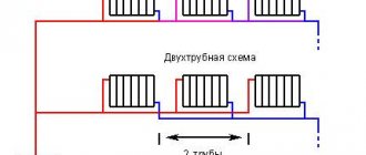
The name of the “two-pipe” system speaks for itself. For operation, two pipes are required: one supplies coolant heated to the required degree, and the second returns it to the boiler to replenish the lost temperature.
This solution allows you to implement both a natural circulation scheme and a forced one, and use boilers using any fuel to heat the coolant. The two-pipe heating system is popular in both individual and large-scale construction.
Connecting a radiator to a two-pipe system
Advantages and disadvantages of single-pipe and two-pipe heating systems
The main difference between the two heating schemes is that the two-pipe connection system is more efficient in operation due to the parallel arrangement of two pipes, one of which supplies the heated coolant to the radiator, and the other removes the cooled liquid.
The single-pipe system circuit is a sequential type wiring, due to which the first connected radiator receives the maximum amount of thermal energy, and each subsequent one heats up less and less.
However, efficiency is an important, but not the only criterion that you need to rely on when deciding to choose one scheme or another. Let's consider all the pros and cons of both options.
Single pipe heating system
Advantages:
- ease of design and installation;
- savings in materials due to the installation of only one line;
- natural circulation of coolant, possible due to high pressure.
Flaws:
- complex calculation of thermal and hydraulic parameters of the network;
- the difficulty of eliminating errors made during design;
- all network elements are interdependent; if one section of the network malfunctions, the entire circuit stops working;
- the number of radiators on one riser is limited;
- it is impossible to regulate the flow of coolant into a separate battery;
- high heat loss coefficient.
Two-pipe heating system
Advantages:
- possibility of installing a thermostat on each radiator;
- independence of operation of network elements;
- the ability to insert additional batteries into an already assembled line;
- ease of eliminating errors made at the design stage;
- to increase the volume of coolant in heating devices, there is no need to add additional sections;
- no restrictions on the length of the contour;
- coolant with the required temperature is supplied throughout the entire pipeline ring, regardless of the heating parameters.
Flaws:
- complex connection diagram compared to a single-pipe;
- higher consumption of materials;
- installation requires a lot of time and labor.
Thus, a two-pipe heating system is preferable in all respects. Why do the owners of apartments and houses refuse it in favor of a single-pipe scheme? Most likely, this is due to the high cost of installation and the high consumption of materials required to lay two highways at once. However, one should take into account the fact that a two-pipe system involves the use of pipes of a smaller diameter, which are cheaper, so the total cost of installing a two-pipe option will not be much more than a single-pipe one.
Owners of apartments in new buildings are lucky: in new buildings, unlike residential buildings of Soviet construction, a more efficient two-pipe heating system is increasingly used.
Types and diameters of pipes
The main requirements for heating pipelines are high temperature resistance, low heat transfer, low hydraulic resistance, long service life, and lack of oxygen permeability when used in metal panel heat exchangers.
When laid externally or hidden under the floor, in walls, these conditions are most closely met by fiberglass-reinforced polypropylene pipes. Polypropylene with an additional aluminum shell is better in terms of temperature and pressure characteristics, but its thermal conductivity is slightly higher.
In practice, most installers of polypropylene heating systems accept that products with a diameter of 32 mm are most suitable for laying two-pipe lines.
To connect the batteries, tee transitions from 32 to 20 diameters are used and, accordingly, they are tied with sections of 20 mm pipes.
In gravity systems, the flow speed is low, therefore, to ensure effective heating, it is necessary to transport large volumes of coolant and, accordingly, an increased cross-section of pipes.
In gravity circuits, it is rational to use supply and return pipelines with a diameter of 40 mm with 25 mm bends for connecting batteries.
If a single-pipe Leningrad line is used, the main pipeline is made with a diameter of 40 or 50 mm (the size depends on the length of the line) with bends for connecting heat exchangers with diameters of 20 or 25 mm, respectively.
To connect panel radiators, the line is often laid under the floor, using materials made of cross-linked PEX or heat-resistant PERT polyethylene with an oxygen-tight shell. Since each heat exchange device has its own branch of short length, which has low hydraulic resistance, the pipe diameter can be reduced, for example, to 16 or 20 mm.
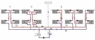
Rice. 10 Scheme of a two-pipe forced associated heating system
Related article:
Heating in a private house from polypropylene pipes - nuances, calculations. It may be interesting to read in more detail about organizing a heating system made of polypropylene pipes in a private house.
Types of two-pipe systems
Two-pipe systems are divided into types depending on:
- circuit type (open and closed);
- method and direction of water flow (flowing and dead-end);
- method of moving coolant (with natural and forced circulation).
Open and closed loop systems
The open-type two-pipe system has not taken root in city apartments due to the peculiarity associated with the upper pipe distribution, which requires the use of an expansion tank. This device makes it possible to control and replenish the heating system with water, but there is not always space in the apartment to install such a large device.
Flow-through and dead-end
In a flow-through system, the direction of water flow in the supply and discharge pipes does not change. With a dead-end circuit, the coolant in the supply and return pipes moves in opposite directions. In such a network, bypasses are installed, and the radiators are located in closed areas, which makes it possible to turn off any of them without disturbing the operation of the heating.
With natural and forced circulation
For natural circulation of water, pipes are laid with a mandatory slope, and an expansion tank is installed at the highest point of the system. Forced circulation is carried out by a pump installed in the return pipe. Such a system requires air vent valves or Mayevsky taps.
Battery Performance
The abundance of various heating radiators that have flooded the modern plumbing market literally provokes consumers to replace outdated cast-iron heating equipment.
The criteria for their selection, first of all, are:
- material,
- operating pressure,
- nameplate thermal power,
- appearance.
At the same time, the possible difficulties of operating the purchased heating device as part of the unpredictable domestic central heating system are not taken into account at all. Foreign manufacturers of beautiful radiators made of aluminum or steel do not at all protect against water hammer when the pressure in the heating radiators jumps to 20-30 atm. corrosion of internal cavities when water is released for six months, from gas formation in aluminum radiators during the flow of coolant with copper impurities and sudden temperature changes. They simply do not have these problems, which cannot be said about the heating systems of our high-rise buildings.
Characteristics of cast iron radiators
- inertness to poor quality coolant;
- working pressure - 9 atm. pressure testing - 15 atm.;
- withstands coolant temperature of 120 0 C;
- disadvantages - afraid of water hammer.
Characteristics of steel radiators
- working - up to 10 atm.;
- coolant temperature - up to 120 0 C;
- well regulated by thermal valve;
- Disadvantage: They are not resistant to corrosion.
Characteristics of aluminum radiators
- working - up to 6 atm. but for reinforced structures - up to 10 atm;
- well regulated by thermal valve;
- disadvantage is susceptibility to electrochemical corrosion and gas formation, which leads to the formation of air pockets.
Characteristics of bimetallic radiators
- working - up to 20 atm. for reinforced structures - up to 35 atm;
- good corrosion resistance;
- coolant temperature - over 120 0 C.
It is important! When planning to purchase new radiators, do not hesitate to contact your housing and communal services structure to find out exactly the operating and test pressure values in your home. Once a year it is submitted, higher than the working one, to identify weaknesses in the system. It may be higher than allowed for your new radiator
It may be higher than allowed for your new radiator.
- Tired of barrel water heaters? Buy a flat boiler!
- Brief overview of some models of water heated towel rails
- Manufacturers of tubular radiators
- A little about aluminum radiators
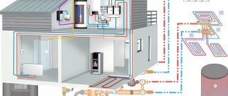
Components of a two-pipe individual heating system
A two-pipe diagram of an apartment’s individual heating network includes the following elements:
- heating boiler;
- thermostatic valves for radiators;
- automatic air vent valve;
- balancing device;
- pipes and fittings;
- radiators;
- valves and taps;
- expansion tank;
- filter;
- temperature manometer;
- circulation pump (if necessary);
- safety valves.
What should be the GOST and SNiP standards for apartment buildings?
The documents stipulate the ranges that provide heating for the building. The indicators are calculated to maintain a temperature of about 20 °C with a humidity of about 40%.
To achieve them, a project is being developed at the pre-construction stage. There are three operating pressure values:
- 2-4 atm for houses up to 5 floors;
- 5-7 for 6-9;
- 12 and above for 10-story and large buildings.
Factors determining indications
Modern houses are equipped with elevators that divide the network into parts. Their goal is to mix streams of water of different temperatures. They are equipped with regulators that control the nozzles. This affects the determination of pressure: a partially closed unit changes the indicator.
The following factors also hinder the achievement of the values specified in GOST:
- The power of devices installed in a building rarely matches the calculations carried out before starting work.
- Equipment condition. It wears out during use.
- Pipeline diameter. Sometimes, during repairs, a section of the piping is replaced by choosing a different size, which leads to a drop in pressure.
- Location of the apartment: the further away from the main line and the boiler, the greater the chance of a decrease in readings.
Checking the norm in multi-storey buildings
This is carried out using pressure gauges at three points:
- on the supply, near the boiler, as well as on the return at a similar point;
- near all used equipment: pumps, filters, regulators, etc.;
- on the highway near the boiler room and at the branch to the house.
Requirements for indicators are determined by GOST and SNiP.
Installation of a two-pipe heating system with upper and lower wiring
The two-pipe system has variations according to the installation scheme. The most commonly used are top and bottom wiring types.
Upper wiring
Laying the top wiring involves installation work to secure the heating system under the ceiling of the room. Batteries installed in places where cold air accumulates (window openings, balcony doors) are supplied with branches coming from the main pipeline. Liquid enters the lower part of the pipeline, which is a drain, and has time to cool during circulation. This system is suitable for large premises; in one-room or two-room apartments, installing heating with overhead wiring is not recommended, since this is unprofitable for the owner from an economic and design point of view.
Installation of a heating circuit with upper horizontal wiring is carried out according to the following scheme:
- The corner fitting required to connect the upward pipe is mounted to the boiler outlet.
- Using tees and corners, horizontal installation of the top line is carried out: the tees are installed above the battery, the corners are installed on the sides.
- The final stage of installation of the upper horizontal is the installation of tees with branch pipes on the battery, supplemented with a shut-off valve.
- On the lower branch, the outlet ends are connected to the common return line, in the section of which a pressure pumping station (circulation pump) is installed.
Bottom wiring
In a network with bottom wiring, outlet channels and supply heat-conducting pipes are installed. The superiority of the lower mounting scheme is expressed in the following:
- The heating pipes are located in the lower, inconspicuous part of the room, which provides more opportunities for the implementation of various design projects.
- Minimum pipe consumption: all installation work is carried out almost at the same level. The wiring point and radiator pipes are located at a short distance from each other.
- Due to the simplicity of the circuit, installation of such a system will be possible even for a non-professional.
Important! The lower wiring is installed only if the circulation of the coolant will be forced, otherwise the water will not move through the heating pipes. This scheme is applicable exclusively in city apartments or one-story buildings.
One of the disadvantages of the scheme is the complexity of adjustment and balancing, but the ease of installation and reliability in operation covers these disadvantages.
- Installation work begins with the outlet from the boiler pipes using an angle fitting in a downward direction.
- The wiring is carried out at floor level along the wall using two pipes of equal diameter. One of them connects the boiler pipe to the entrance to the battery, the other is connected to the receiving pipeline.
- Connections between radiators and pipes are made using tees.
- The expansion tank is located at the highest point of the supply pipe.
- The end of the outlet pipe is connected to the circulation pump; the pump itself is located at the entrance to the heating tank.
Setting maximum values
Maximum pressure standards in the heating system are set taking into account the characteristics of the equipment and pipes used.
For example, the following limits apply for radiators: cast iron batteries - up to 6 atm, plastic 2-4 atm. The weak points are the joints of the heating system elements.
The maximum values are set in the following sequence:
- Pressure testing of the system. The circuit is filled with water under pressure exceeding the operating value by 2-2.5 times. During pressure testing, the change is monitored by a pressure gauge.
- Checking for leaks. Testing is carried out in 2 stages - cold and hot testing. At the first stage, the system is filled with cold water with minimal operating pressure. It is kept in this state for 2 hours. If during this time the indicators have decreased by no more than 0.2 atm, then we can talk about good tightness. At the second stage, the heating boiler is turned on at full power and the line is filled with hot coolant at maximum operating pressure. The change in parameter is controlled by a pressure gauge.
- Setting the working pressure. After testing is completed, the valve releases excess pressure and sets the operating value.
Testing the system at maximum levels helps to identify problem areas, including leaks. All violations are corrected immediately. You cannot start operating the system without eliminating weak points.
Source
How to make a calculation
Without a preliminary calculation of the power of the future heating system, it is quite difficult to achieve comfortable heat in the house. Thermal calculation helps to choose:
- heating boiler of optimal power;
- radiators with the required number of sections;
- pipes, shut-off valves, etc.
For thermal calculation you will need the following data:
- The total area of the building and each room separately, ceiling height.
- The purpose of each room (bedroom, living room, kitchen, utility room, etc.).
- The presence of buildings adjacent to the building.
- The material from which the building is constructed (walls and ceiling, floor and ceilings, roof).
- Type of insulation used.
- Number, type and sizes of windows and external doors.
- The duration of the heating season and the “wind rose” of the area, average temperature minimums in a given period.
- Desired temperature in the house.
- Connection points to communications (gas, electricity, water supply).
Power and heat dissipation
Calculation of the required thermal power will allow you to select the exact model of the heating boiler and radiators.
Method 1. Calculation of heating power by area:
Q=S×A×k, where:
- Q – Thermal power (watt).
- S – Internal area of the building (m²).
- A - The number of watts of the total power of the heating system per 1 m² (usually 100 - 150 watts).
- k – Power reserve factor in case of severe frosts (1.2 or 1.25).
Important: Sometimes it is not practical to calculate the power of a room in a single field. It is better to divide the area into residential and technical. For the first, the indicator is A=100 or 150 watts, for the second, A=50 or 75 watts.
This method is simple, but is not always the optimal solution, because... does not take into account the climatic characteristics of the region, nor the height indicators of the premises, nor the characteristics of the materials from which the house is built, etc.
Method 2. Calculation of heating power based on the volume of the room and the climatic characteristics of the region.
Q= (S×B×C×X) + (E×200+F×100), where:
- Q – Thermal power (watt).
- S – Internal area of the building (m²).
- B – Wall height (m).
- C – Correction coefficient of heat loss (for detached buildings, for example, it is equal to 60).
- X – Regional coefficient.
- E – Number of doors.
- F – Number of windows.
| Winter type | Region | Regional coefficient |
| Warm winter | South, Black Sea coast | 0,7 — 0,9 |
| Moderate winter | Central Russia, North-West | 1,2 |
| Harsh winter | Siberia | 1,5 |
| Extremely cold winter | Chukotka, Yakutia, Far North | 2 |
Hydraulic calculation
The coolant pressure created in the system is not a constant value. It is constantly influenced by the friction force created in the pipeline, adjustment of temperature indicators, etc. This can lead to unbalancing of the heating circuit.
This can be avoided by hydraulic calculation, which ensures that each radiator receives the coolant in the amount necessary to maintain the specified parameters. During the calculation, the following are determined:
- pipe diameter and capacity;
- potential pressure loss locations;
- optimal volume of coolant;
- hydraulic linkage conditions.
We calculate the volume of coolant based on the boiler power:
V= 13.5×Q, where:
- V – Volume of water mass of the heating main.
- 13.5 – Wed. volume of coolant per unit of boiler power.
- Q – Boiler power (kW).
The volume of coolant can also be calculated based on the actual capacity of the circuit, when all the volumes of the constituent elements of the circuit (pipes, radiators, etc.) are summed up.
Calculation of coolant movement speed:
V= (Q×L×0.86):(K-Ko), where:
- V – Coolant movement speed (m/s).
- Q – Boiler power (watt).
- L – boiler efficiency.
- K – Coolant temperature at the boiler outlet.
- Ko – Return coolant temperature.
The optimal speed of fluid movement is considered to be in the range from 0.3 to 0.7 m/s. Deviation from the established standard threatens either airing of the circuit or excessive noise.
Pipe diameter
The determination of the pipe cross-section is based on the results of thermal and hydraulic calculations.
D= √354×(0.86×Q):(K-Ko):V, where:
- D – Pipe cross-section (cm).
- Q – Boiler power (watt).
- K – Coolant temperature at the boiler outlet.
- Ko – Return coolant temperature.
- V – Coolant movement speed (m/s).
The calculation is quite complex, so it is easier to use ready-made tables or special online calculators, widely available on the Internet.
As a result of all calculations, a plan for individual heating of a private house (apartment) is drawn, indicating the diagrams and data of each element of the system.