A single-pipe heating system is one of the solutions for laying pipes inside buildings with the connection of heating devices. This scheme seems to be the simplest and most effective. The construction of a heating branch using the “one pipe” option is cheaper for homeowners than other methods.
To ensure the operation of the scheme, it is necessary to perform a preliminary calculation of a single-pipe heating system - this will allow you to maintain the desired temperature in the house and prevent a loss of pressure in the network. It is quite possible to cope with this task on your own. Do you doubt your abilities?
We will tell you what the design features of a one-pipe system are, give examples of working diagrams, and explain what calculations must be performed at the planning stage of the heating circuit.
What is single-pipe heating?
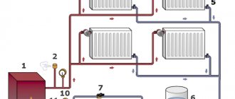
Any heating system consists of the following components:
- Heating device (boiler). Can be solid fuel, electric, gas, etc.
- Heat-dissipating devices. Batteries or underfloor heating system.
- A device for creating circulation inertia of the coolant. This could be an accelerating section of the main line or a water pump.
- Compensator for excess coolant pressure in the system. Expansion tank (open or closed).
- Pipes, fittings and necessary fittings.
The choice of heat supply scheme is directly dependent on the type of devices used.
Hydraulic linkage
Balancing pressure drops in the heating system is carried out using control and shut-off valves.
Hydraulic linking of the system is carried out on the basis of:
- design load (coolant mass flow);
- data from pipe manufacturers on dynamic resistance;
- the number of local resistances in the area under consideration;
- technical characteristics of fittings.
Installation characteristics - pressure drop, fastening, flow capacity - are set for each valve. They are used to determine the coefficients of coolant flow into each riser, and then into each device.
Pressure loss is directly proportional to the square of the coolant flow rate and is measured in kg/h, where
S is the product of dynamic specific pressure, expressed in Pa/(kg/h), and the reduced coefficient for local resistance of the section (ξpr).
The given coefficient ξpr is the sum of all local resistances of the system.
Installation recommendations
In addition to the general rules for installing heating equipment and heating networks, when assembling single-pipe systems with your own hands, you need to take into account its features. Here are some recommendations on the topic:
- first make a correct calculation of pipe diameters, especially for a gravity flow scheme;
- think carefully about the laying of branches or risers so that the former do not cross doorways, and the latter do not fall on the windows;
- Connect radiators for artificial circulation using a DN15 pipe, and for natural circulation – DN20;
- Observe slopes. For a gravity system - at least 5 mm per 1 m, pressure - 3 mm;
- the height of the accelerating manifold should be 2.2 m;
- the expansion tank in an unheated attic must be insulated, and the overflow pipe must be taken outside;
- if the boiler heat exchanger is made of cast iron, do not add cold water directly to the return line near the heat generator;
Do not load one ring of the heating circuit with a large number of batteries, otherwise the last ones will be cold.
Pros and cons of single-pipe wiring
We will try to give an objective assessment and highlight the real advantages of single-pipe water systems:
- A closed circuit with a membrane expansion tank is easier to install. One pipe is laid faster than two.
- It is easier to hide a single main or riser in the walls than double-pipe branches (example in the photo below). The fly in the ointment: the ring manifold crosses doorways, making installation difficult.
- A heating network with risers is indispensable when it is necessary to organize gravity flow in a building of 2-3 floors. There is no point in passing two pipelines through the ceiling; one vertical line is enough.
- Installation is cheap in one case: when a gravity heating system is used in a one-story private house. Savings are achieved by laying one main line instead of two (remember, gravity flow a priori requires pipes of large diameters Ø48-57 mm).
- The closed type system can be automatically controlled using thermostatic radiator valves. Disclaimer: it is necessary to take into account the specifics of the operation of heating devices and choose the right fittings. We will return to this issue below.
Small diameter pipes are walled up in the walls, large diameter pipes are covered with decorative screens
Note. Direct connection of a section of heated floors cannot be considered an advantage of this scheme. The heating circuit is just as easily connected to the two-pipe distribution.
The main problem of the Leningradka is the cooling of the coolant as it moves towards the distant batteries. It is impossible to increase radiator sections and the cross-section of the main line indefinitely; the optimal number of devices is 4-5 pieces. on one circuit.
We list other disadvantages:
- Hydraulic instability is the effect of one battery on the operation of the others. If you close the first radiator valve, subsequent appliances will receive hotter water and begin to overheat the rooms.
- In order for the coolant to flow well into the radiators with a closed Leningrad circuit, it is necessary to use full-bore fittings on the branches. An increase in the hydraulic resistance of the line causes water to flow further in a straight line, and the coolant flow through the battery decreases.
On the left is a standard angle valve with a small hole, on the right is a thermostatic radiator valve with an increased flow area - “Leningradka” and vertical wiring are more expensive than a two-pipe shoulder circuit. If we add the costs for additional radiator sections, then the cost of installation from cross-linked polyethylene will be comparable to a radial system, where fittings are not used, but there is a distribution comb.
- The circuit is complex to calculate and configure (balance). The power and heat transfer surface area of the batteries must be determined as accurately as possible.
An additional disadvantage of gravity distribution is the large diameters of pipes laid with a slope of 3-5 mm per linear meter. Risers coming out of the ceilings stick out in plain sight and spoil the interior of the premises. It is not always possible to wall pipelines into walls; you have to get sophisticated and make decorative boxes.
Disadvantages of the system and possible ways to eliminate them
Like any heating system, the Leningradka is not without its drawbacks. However, today there are ways to eliminate them.
- The first drawback is related to the principle of its operation: as you move away from the heat source, the temperature of the radiators becomes lower and lower, and, accordingly, the rooms will be cool. This problem can be solved by increasing the number of sections or the area of heating devices in each subsequent insert. Another option to ensure balance, i.e. uniform heating to the required temperature is the installation of shut-off and control valves: taps, cone valves, regulators, thermostatic valves, bypasses, etc.
- Another imperfection of such a system (in the classical version) is the impossibility of regulating the temperature and repairing one of the elements without completely stopping its functioning. However, currently such a scheme is found only in old houses. Modern options already include the installation of the above equipment, which allows you to change the degree of heating of each specific radiator, as well as its replacement without affecting the operation of others.
- The use of metal pipes not only increases the cost of the Leningradka, but also complicates its installation and repair. The way out of this situation is to use metal-plastic or polypropylene pipes.
- Like any single-pipe system, for effective operation the Leningradka requires increased coolant pressure in the pipeline. This problem can be eliminated either by increasing the heating temperature of the liquid, which is not always acceptable, or by installing a circulation pump.
Why choose such a system?
Two-pipe water heating is gradually replacing traditional single-pipe designs, since its advantages are obvious and very significant:
- Each of the radiators included in the system receives a coolant with a certain temperature, and it is the same for all.
- Ability to make adjustments for each battery. If desired, the owner can install a thermostat on each of the heating devices, which will allow him to obtain the desired temperature in the room. At the same time, the heat transfer of the remaining radiators in the building will remain the same.
- Relatively small pressure losses in the system. This makes it possible to use an economical circulation pump of relatively low power to operate the system.
- If one or even several radiators fail, the system can continue to operate. The presence of shut-off valves on the supply pipes allows for repair and installation work to be carried out without stopping it.
- Possibility of installation in a building of any number of floors and area. You just need to choose the optimal type of two-pipe system.
The disadvantages of such systems usually include the complexity of installation and higher cost, compared to single-pipe structures. This is due to the double number of pipes that have to be installed.
However, it must be taken into account that to install a two-pipe system, pipes and components of small diameter are used, which provides certain cost savings. As a result, the cost of the system is not much higher than that of a single-pipe analogue, but it provides much more advantages.
One of the significant advantages of a two-pipe heating system is the ability to effectively regulate the room temperature
Scheme of a single-pipe heating system: types and advantages
Single-pipe heating systems are divided into a single-pipe heating system with a closing loop and a flow-through single-pipe system. The single-pipe method of installing heating systems has two types:
The first type is flow-through
The first scheme is flow-through. There are no supply risers as such. Radiators throughout the entire height of the house are connected to each other in series.
The hot water flow is supplied from top to bottom and flows sequentially through all heating radiators, starting from the top. The lower radiators in such a system will be cooler.
Scheme of a single-pipe system with flow-through heating.
In flow-through types of single-pipe systems, the coolant mixture, flowing through the pipes, passes sequentially through the entire chain of heating radiators, gradually cooling at each of the batteries.
As a result, it will be quite hot on the upper floors, and on the lower floors the heating temperature may not even be sufficient.
To reduce this difference and to balance heat loss, batteries with a large number of sections are installed on the lower floors of buildings.
In flow-through systems, it is not recommended to install control valves, because even if the flow is reduced or such a valve is closed in a particular radiator, the water supply to all batteries lying below in a given riser in the direction of flow is reduced or shut off.
In such systems it is impossible to regulate the air temperature in the rooms. If the house has two floors, then it is impossible to supply water to only one of the floors.
Many years of experience show that such a single-pipe heating system scheme is absolutely ineffective, and therefore is not used today.
The second type - with bypasses
Comparison of a single-pipe heating system with a closing loop and a flow-through single-pipe system. Click to enlarge.
A single-pipe space heating system has a closing circuit and uses special fittings with a bypass inside the housing of these fittings.
From the heating radiator, the coolant flow with a decreased temperature is consistently returned to the riser.
After this, the coolant mixture is supplied to the next radiator. The annular water flow is divided in the valve into flows in the radiator and flow in the bypass.
From the risers, water flows into the upper radiators, the rest of the hot flow is directed down the risers to the underlying radiators.
The water in this connection cools down somewhat less, which makes it possible to reduce the temperature difference on the lower and upper floors.
This connection method is, in essence, a modernized “flow-through” system, in which a jumper is created between the radiator connection pipes - a bypass.
The diameter of the pipe of such a closing section is made one size smaller than that of the riser pipes of the general connection. As a result, the coolant supplied from the upper floors is divided into two flows: the first flows into the battery, and the second, through the bypass, flows to the lower rows of radiators.
If the diameter of the bypass is mounted the same as that of the connection pipes, then the coolant in the radiator will stop circulating, since the hydraulic resistance in the battery will be greater than in the bypass.
Water always flows where there is less hydraulic resistance; with the same diameter, it does not need to flow through the radiator; it will flow calmly through the closing section, which has the same size of pipe from which it flowed.
When installing bypasses with diameters equal to the diameter of the riser pipes connecting the radiators, the incoming amount of water can be regulated by pre-installed valves (to balance the system). Such taps are mounted on the connection pipe and on the bypass.
For example, you can completely shut off the radiator itself and redirect all the water to the bypass, and then to the heating batteries lower down the riser. Or vice versa - shut off the bypass and direct the entire flow of coolant into the battery itself.
Calculation of the number and power of batteries
Both in single-pipe connection of heating radiators and in two-pipe schemes, the heating efficiency of a particular room depends not only on the number of radiator sections, their design, the material from which they are made, surface area and method of connection to the main pipeline, but also on the material of the walls and insulation method, heat loss in windows, etc.
Let's use the recommended data that can be found in specialized literature. 1 m3 in a brick house requires approximately 0.034 kW of heat to maintain a comfortable temperature; in a house made of SIP panels – 0.041 kW; in a brick house with insulated: ceiling, attic, load-bearing walls, foundation - 0.02 kW.
For example, let's consider the selection of batteries for a room of 18 m2 with a ceiling height of 2.5 m in a brick house. (0.034 kW).
- Let's find out the volume of the room: 18 x 2.5 = 45 m3.
- We calculate how much thermal energy is needed for a given room: 45 x 0.034 = 1.53 kW
Now you need to use the table with battery characteristics.
The figure shows the main characteristics of the most common radiators. Based on the data presented, aluminum batteries have the best performance-to-cost ratio. We need data on the power of one section, the lower limit of which is 0.175 kW.
- We divide the result by the power of the section of the selected type of radiator and get the number of sections: 1.53 / 0.175 = 8.74
Bottom line: to heat a room of 45 m3, we need an aluminum radiator consisting of 9 sections. Carry out similar calculations for each room in the house.
Existing modifications of the single-pipe heating system Leningradka
The design feature of this heating option allows it to be performed in two versions: horizontally and vertically.
Horizontal scheme
In this case, the contour is laid along the perimeter of the building (floor). In this case, the supply line can be located both above the floor covering and directly in the floor structure. In the second method, it is recommended to insulate the heating pipeline to eliminate heat loss.
Figure 2 – Horizontal diagram of a single-pipe “Leningrad”
Figure 3 – “Leningradka” with the location of the supply line in the floor structure
The horizontal heating circuit can be open or closed.
The open type involves installing an expansion tank at the top of the system, communicating with atmospheric air. The closed-type Leningradka eliminates this possibility, so it uses a membrane tank, which is installed in the same room where the heat source is located.
Vertical scheme
This design is similar in design to the traditional single-pipe system used in multi-storey buildings: radiators must be placed one under the other and connected to a single pipeline. The difference is that the coolant does not move along one riser (i.e. only from top to bottom), but along a circuit (heated water first rises to the upper floor, passing through installed appliances, and then descends to the lower level, passing through the second group of radiators ).
Figure 4 – Vertical diagram of the “Leningradka”
Which heating network layout to choose?
You need to start calculations “from the stove”, in the literal sense of the word. Hydraulic calculations of a two-pipe heating system can only be performed after it has been determined what fuel the boiler installed in your installation will operate on.
After this, you can begin the actual calculations, the main goal of which is:
- Determination of the required number of heating devices and pump power.
- Clarification of the number and total length of pipelines, their required diameters.
- Determination of probable heat losses.
All calculations are carried out according to a heating diagram previously drawn to scale, onto which all its constituent elements should be plotted, down to the last tap. In addition to it, you will need basic formulas, special calculation tables and an appropriate program (all this is easy to find on the Internet).
This procedure is mandatory when calculating any heating system. In single-pipe circuits, this is also quite difficult to do, since the coolant cools more and more in each subsequent radiator. To maintain a certain temperature, it is necessary to increase the speed of the coolant at each subsequent section of the circuit. This can be done by reducing the diameter of the pipe, according to the required thermal power for each radiator.
Calculations can be made using the formula Rср = β*?рр/∑L; Pa/m. We obtain the average value of pressure loss due to friction per 1 meter of the design ring CO. Next, using the formula, we calculate the diameter of the pipeline for a specific section of the circuit.
∆t° - difference in coolant temperature between the inlet and outlet of the boiler unit, °CQ - amount of heat required to heat a particular room V - coolant velocity, m/s
A few words about the speed of water movement in the system. For heating to work efficiently, it is necessary that the speed of movement of the coolant be as high as possible. However, this increases the pressure in the system and creates noise from friction against the surface of the pipeline. The optimal coolant speed in a horizontal single-pipe heating system should be in the range of 0.3 - 0.7 m/sec. Slower - airing is possible; Faster - noise appears.
There are tables in which you can select the required pipe diameter. For this diameter, the optimal speed and coolant flow rate is proposed. Let's consider an example of selecting reinforced polypropylene pipes for each section of a heating circuit with 6 radiators of different power.
- In the first section of the CO (from the boiler outlet to the radiator), the system power is 15 kW. Select the data corresponding to the power from the blue columns. A pipe with an internal diameter of 20 mm and 25 mm is suitable. We choose 20 mm (it is cheaper). The coolant movement speed in this area will be 0.6 m/s; coolant flow through a pipe of this diameter at a given speed is 659 kg/h.
- The first radiator has a power of 3 kW, so the load on it is already 15 - 3 = 12 kW. In the optimal zone of the table, this value is in the zone of the 20 mm pipe.
- In the area between the first and second radiator: 12 kW – 2.5 = 9.5 kW; pipe diameter 20 mm.
- On the third radiator, the heat load drops to 9.5 - 2 = 7.5 kW. Based on the table, a pipe with an internal diameter of 15 mm is required in this section.
The calculation of the pipeline is done in a similar way in all sections of the CO.
Tip: You should be aware that reinforced polypropylene has slightly different internal dimensions than indicated in the table. The example we showed with an internal diameter of 20 mm actually has 21.2 mm. and marking PP32, and accordingly the outer diameter is 32 mm.
A technical feature of this type of heating system is that it consists of two pipelines. One is used to transport coolant heated in the boiler directly to heating sources - radiators. And the second circuit is necessary for the outflow of already used coolant from the radiators - the cooled liquid that has given up its heat.
In a system such as a passing two-pipe heating system, there is an equal temperature of the coolant entering simultaneously into the heating devices of the system.
Many believe that the cost of a two-pipe system, compared to a simpler one-pipe system, almost doubles - after all, it is necessary to take twice as many pipes. But that's not true. The fact is that in order to properly build a properly functioning one-pipe system, pipes of larger diameter should be used, since they contribute to a more active movement of coolant and waste liquid. And when creating a two-pipe system, pipes of much smaller diameter are used, the cost of which is lower.
The same situation is observed when purchasing additional system components - valves, fittings, connecting elements. Products with larger diameters are more expensive. That is, we can draw a simple conclusion - in fact, purchasing materials for a two-pipe system will not cost you much more than for a single-pipe system. But the efficiency of its work is much higher.
Basic elements of a two-pipe heating system
Another significant advantage of a two-pipe system is that in such a heating system it is possible to install valves on each radiator, through which the heating level of the element can be controlled. In addition, using such valves you can also significantly save water and electricity consumption for heating it.
Many owners of houses with a single-pipe system are often upset that a very thick heating pipe cannot be hidden - and this significantly spoils the overall impression of the room. While the pipes used in a more complex two-pipe system are thinner - and hiding them will not be difficult. And even if the pipes are visible, they do not attract much attention.
Considering all the obvious advantages of a two-pipe system - greater efficiency, low cost and aesthetics, you can confidently choose it. This is what most owners of country houses do.
Heating system of a private house
There are two types of two-pipe heating systems - horizontal and vertical 2-pipe heating systems. The main difference between these types is in the axis of the pipeline location. These pipes are used to connect all elements of the heating system. Of course, each type has its own disadvantages and advantages. Common to both types are the following advantages: excellent hydraulic stability and a high level of heat transfer.
A horizontal two-pipe heating system should be installed in one-story buildings where the heating pipeline is quite long. In such houses, connecting heating radiators to a horizontally located system is the most practical solution to the issue.
Horizontal two-pipe heating system
A vertical two-pipe heating circuit is somewhat more expensive than a horizontal one. However, since the riser is located vertically, this allows it to be used even in multi-story buildings. In this case, each floor separately cuts into the central heating riser. In addition, the advantage of the vertical type of heating system is that air does not accumulate in it - if bubbles arise, they immediately rise vertically, directly into the expansion tank.
Vertical two-pipe heating circuit
Whatever type of system you choose, you should keep in mind that balancing must be carried out. When choosing a vertical system, balancing a two-pipe heating system requires the riser itself. When horizontal adjustment of a two-pipe heating system takes place, the loops are subject to it.
Features of the horizontal pipe laying scheme
Horizontal heating scheme in a two-story house
In the vast majority, a horizontal two-pipe heating system with bottom wiring is installed in one or two-story private houses. But, in addition, it can be used to connect to centralized heating. A feature of such a system is the horizontal arrangement of the main and return (for two-pipe) lines.
When choosing this piping system, it is necessary to take into account the nuances of connecting to various types of heating.
Central horizontal heating
To draw up an engineering diagram, you should be guided by SNiP 41–01–2003. It states that the horizontal distribution of the heating system must ensure not only proper circulation of the coolant, but also ensure its metering. For this purpose, two risers are installed in apartment buildings - with hot water and for receiving cooled liquid. A calculation of a horizontal two-pipe heating system, which includes the installation of a heat meter, is required. It is installed on the inlet pipe immediately after connecting the pipe to the riser.
In addition, hydraulic resistance in certain sections of the highway is taken into account
This is important, since the horizontal distribution of the heating system will only work effectively if the appropriate coolant pressure is maintained
Autonomous horizontal heating
Heating with natural circulation
In a private house or apartment without a connection to the central heating supply, a horizontal heating system with bottom wiring is most often chosen. However, it is necessary to take into account the operating mode - with natural circulation or forced under pressure. In the first case, a vertical riser is installed immediately from the boiler to which the horizontal sections are connected.
The advantages of this arrangement for maintaining a comfortable temperature level include the following:
- Minimum costs for purchasing consumables. In particular, a horizontal single-pipe heating system with natural circulation does not include a circulation pump, a membrane expansion tank and protective fittings - air vents;
- Reliability of operation. Since the pressure in the pipes is equal to atmospheric pressure, the excess temperature is compensated using an expansion tank.
But there are also disadvantages to be noted. The main one is the inertia of the system. Even a well-designed horizontal single-pipe heating system for a two-story house with natural circulation will not be able to quickly heat the premises. This is explained by the fact that the heating network begins to move only after reaching a certain temperature. For houses with a large area (from 150 sq. m.) and with two floors or more, a horizontal heating system with bottom wiring and forced circulation of liquid is recommended.
Heating with forced circulation and horizontal pipes
Unlike the scheme described above, there is no need to make a riser for forced circulation. The coolant pressure in a horizontal two-pipe heating system with bottom wiring is created using a circulation pump. This is reflected in improved performance:
- Quick distribution of hot water throughout the entire line;
- Possibility of adjusting the volume of coolant for each radiator (only for a two-pipe system);
- A smaller area is required for installation since there is no distribution riser.
In turn, horizontal wiring of the heating system can be combined with a collector one. This is relevant for long-distance pipelines. This way you can achieve even distribution of hot water throughout all rooms of the house.
When calculating a horizontal two-pipe heating system, it is necessary to take into account the rotary units; it is in these places that the hydraulic pressure losses are greatest.
Data collection and preparatory calculations
First of all, let’s answer what is hydraulic calculation needed for?
- For efficient heating of all rooms, regardless of external and internal air temperatures.
- To reduce operating costs that arise during the operation of heating equipment.
- To reduce costs associated with the purchase of equipment and materials. This concerns the competent selection of pipeline diameters in each section of the heating system.
- To reduce the noise level associated with the movement of coolant along the circuit.
- For stable operation of the heating system.
In order to make a calculation of the heating system (this story will talk exclusively about a single-pipe scheme with forced circulation of the coolant), it is necessary to obtain the following data:
- The required power of the heat generator.
- Power and number of radiators for each heated room.
- Diameter and length of the heating circuit.
Having the required data in hand, you can proceed to selecting a circulation pump, calculating the amount of coolant, the capacity of the expansion tank and setting up the safety group. Now let's talk about everything in order.
Elimination of deficiencies using bypass
In addition, natural circulation achieves a reduction in the heating effect, and this will be felt on devices located at the farthest point; problems may also arise with heating the lower riser. It will warm up less. Everything depends on the correct installation of the system, and in this case, even devices with forced circulation will not be able to correct the defect. In this case, a bypass is used to close the coolant circulation. In simple words, this is a piece of pipe connecting the supply and return.
There is another option to correct the situation, but it is more complicated. The method consists of parallel insertion of all radiators into the main line, and additionally supplying them with control valves. And most importantly, it becomes possible to repair individual devices without draining the coolant.
Advice. Such installation is necessary if the heating boiler exceeds the system parameter in strength. The valves allow you to balance the temperature and not overheat individual rooms.
A two-pipe system, unlike a single-pipe supply, does not have such inconveniences. But everything is stopped with auxiliary devices. The bypass is equipped with valves that shut off the flow. If desired and possible, it can be made from the remains of pipes. The bypass circumference should be slightly smaller than the diameter of the risers. Otherwise, the liquid will not be evenly distributed, but will be discharged directly into the return line.
Experts recommend an approximate difference in diameter, from 5 to 10 mm. To achieve greater effect, the bypass should be located closer to the radiator. At the outermost device, just before the hole at the inlet, a thermostat is mounted. By taking into account these little things, the operation of heating devices will be more efficient. During acceleration, the same return will be natural and also forced circulation. The difference in thermal performance will be insignificant, even if you have to install the appropriate equipment in the process.
DIY installation
Following simple rules will allow you to install a 2-pipe heating system yourself:
- A circuit is placed on top that supplies heated coolant from the boiler to the radiator. Bottom - to return waste liquid back to the boiler.
- The highways are laid parallel to each other.
- The heating circuit must have a slope away from the heating element towards the outer radiator.
- To reduce heat loss, the central riser must be insulated.
- To allow repair of individual sections of the heating network, blocking valves are installed.
- It is advisable to minimize the number of angles that reduce the speed of coolant movement.
- It is necessary to accurately select circuit elements for the cross-section of the pipes used.
- Every 1 - 1.2 m the pipeline must be supported by a system of fasteners (especially when using metal pipes).
Installation should be performed in the following sequence:
- A central riser is connected to the installed heating boiler.
- The central riser is connected to the expansion tank.
- From the tank there is a branching pipeline with a phased installation of heating devices.
- The installation of a parallel waste liquid return line begins from the bottom of the boiler.
- A pump is mounted at the inlet or outlet of the boiler (less often) (if necessary).
How to connect radiators
There are 3 ways to connect radiators:
- One-sided (lateral). Heat transfer is about 95%. Recommended when connecting radiators with up to 15 sections.
- Diagonal (cross). Heat transfer is about 100%. Suitable for batteries with 15 sections or more.
- Lower. Heat transfer is about 85%. Most often used with a hidden pipeline laying concept.
How to balance the system
Without balancing, radiators farthest from the boiler will warm up according to the residual principle, even at maximum boiler operation.
- Method 1. Electronic flow meter based on calculated data.
The most correct method, however, is impossible to carry out without a design and hydraulic calculations. In addition you will need:
- control valves on each riser;
- balancing valve with fittings for connecting electronics;
- special equipment connected to the control valves.
An electronic device for precise temperature control is connected to the valve fittings and measures the actual coolant flow. Then, by turning the spindle, the target values are set.
Important. Currently, you can purchase a special balance valve equipped with a flow meter bulb. This device makes it possible to balance the system by analogy with the method described above.
- Method 2. Balancing each radiator by temperature.
To do this, each battery must have a control valve installed at its output. You will also need a special thermometer to measure the temperature of the metal valve body.
- The valve on the outermost battery of the circuit opens completely.
- The rest in the row are unscrewed several turns according to the principle of increasing from the boiler. For example, the first radiator from the boiler is 1 turn, the second is 2 turns, etc.
- The temperature is measured at each valve of the circuit until it is equalized at all.
How much would it cost to install such a system?
The cost of installing double-circuit heating depends on a number of factors:
- room area;
- the cost of the equipment and materials used;
- type of heating (warm floors, convector radiators, etc.) and, accordingly, the complexity of the work;
- type of temperature control (manual or automatic);
- the need to connect hot water supply and much more. etc.
For example, a house with an area of 100 m² at average rates will be about 260,000 rubles. The minimum level is about 160,000 rubles.
By doing the work yourself, you can reduce these costs by almost 2 times.
Two-pipe scheme
Two-pipe heating system. Click on photo to enlarge.
A two-pipe heating system with bottom wiring differs from the top supply of risers in that both pipes (both supply and return) are located at the bottom. The hot coolant moves along the direct riser from bottom to top, passes through all the batteries and returns through the return riser to the boiler. A two-pipe circuit may contain one or more circuits and provide a passing or dead-end movement of water through the supply and return pipes.
A two-pipe heating scheme with natural circulation and lower risers is used infrequently, since a large number of final radiators requires the installation of an equally large number of air valves, and manually bleeding air from the radiators is a labor-intensive and tedious process. Looping the supply risers with special air pipelines helps solve the problem of air entering the main line through the expansion tank, but then the whole point of using the lower line is lost, because the number of risers on the walls does not decrease, but only increases.
Requirements for organizing a two-pipe system with bottom wiring
The required components of such a highway are:
- boiler;
- batteries;
- connecting pipes;
- expansion tank;
- pump;
- adjustment devices (pressure gauge, balancing device, air vent);
- other fittings (valves, thermostatic and safety valves, pipeline filters).
The expansion tank should be located at the peak - the highest point of the heating system. If the house has a central water supply, then the expansion tank can be combined with a water supply tank to the main line. The main condition for effective use of the tank is easy access to it, so it is not at all necessary to place it in the attic, as is the case in many private homes. In addition, the tank must be installed in a cool place.
For natural circulation, it is necessary to create a pipe slope at the rate of 10 cm per 20 linear meters.
If the front door becomes an obstacle to installing risers, you can arrange two elbows. In this case, the wiring is equipped from the peak of the main line.
Another important requirement for the effective operation of a two-pipe heating main is the use of pipes of different diameters, designed to ensure the movement of the coolant not only in a small circle (boiler - nearby radiator - boiler), but also in longer ones. In long lines it is advisable to include a high-performance electric pump
It will accelerate the circulation of water, which means the heat transfer of the batteries will be higher
In long lines it is advisable to include a high-performance electric pump. It will accelerate the circulation of water, which means the heat transfer of the batteries will be higher.
When designing a two-pipe heating system, competent hydraulic calculation is of decisive importance, the main function of which is to determine the required number of radiators for effective heating of the house, the diameter of the risers and possible heat loss.
Installation options for control valves
So, you have decided to create a one-pipe heating system for a private house with your own hands. The first thing you need to do to find out the required power value of the heat generator is to calculate the heat loss of each heated room. As you know, the main heat losses come from:
- External walls.
- Ceiling.
- Paula.
- Windows
Using an example, consider the heat loss of a corner room with dimensions of 6 x 3 meters, two windows 1.5 x 1.2 m, and a ceiling height of 2.5 m.
- External walls (S1) = (6 x 2.5) (3 x 2.5)-2 (1.5 x 1.2); S1= 15 7.5-3.6=18.9 m2
- Windows (S2) = 2(1.5 x 1.2) = 3.6 m2
- Floor (S3) = 18 m2
- Ceiling (S4) =18 m2
We apply the formula for calculating heat loss (Q) = k; for external walls k = 62; for windows k = 135; for floor k = 35; for the ceiling k = 27. Substitute the required values.
- Q1 = 18.9 x 62 = 1171.8 W or 1.172 kW;
- Q2 = 3.6 x 135 = 486 W or 0.486 kW;
- Q3 = 18 x 35 = 630 W or 0.63 kW
- Q4 = 18 x 27 = 486 W or 0.486 kW;
Now we sum up all the heat losses to identify the required amount of heat required for a specific room = 2.774 kW;
The same steps are necessary for each individual room. By summing up the heat loss, we can draw a conclusion about the required performance of the boiler installation. There is a less accurate method, but quite reliable and fast: it is necessary to use the specific power of the boiler unit recommended depending on the region.
Wк = boiler power;
Wsp = recommended specific power shown in the figure;
S/10 = area of the heated room per 10 m3.
Now that we have data on the power of the boiler unit required to heat the house, we can begin drawing the heating system circuit and estimate the location of the heating radiators.
Figures 11, 12, 13 show examples of installing manual balancing valves and automatic differential pressure regulators in two-pipe heating systems. Linking the heating system with the help of thermostatic valves, control radiator valves, balancing valves and automatic differential pressure regulators eliminates excessive heat consumption in the rooms first along the flow of the coolant (an excess of the air temperature in the room above the design value by 1–2 ° C leads to excess heat consumption by 6–10 %) and underheating of remote premises.
In Fig. Figure 11 shows examples of installing fittings on risers during static (a) and dynamic (b) balancing and thermostatic valves on instrument connections. The connection of instrument branches on the riser is realized using thermostatic valves HERZ TS-90-V with pre-setting. Pre-setting of thermostatic valves at the same coolant flow rates increases along the coolant flow, while the pressure losses on the thermostatic valves decrease, thereby ensuring equality of pressure losses in the instrument branches of the riser.
Rice. 11. Diagram of a fragment of a vertical dead-end two-pipe water heating system with lower routing of both lines a) static balancing; b) dynamic balancing
For hydraulic linking of heating system risers, you can use manual balancing valves (static balancing) and automatic differential pressure regulators (dynamic adjustment), which provide the necessary pressure losses on the risers and, accordingly, the calculated values of coolant flow.
For option “a”, when the heating system operates with variable loads, for example, during the transition period of the heating season, there is a potential possibility of exceeding the maximum permissible pressure drop across the thermostatic valves, as well as redistributing the coolant flow between heating devices and risers.
For option “b”, by maintaining a constant pressure difference between the risers, using the HERZ 4007 automatic differential pressure regulator, the required conditions for the operation of thermostatic valves are ensured and the redistribution of the amount of coolant between the risers is eliminated throughout the entire period of operation of the heating system.
In Fig. Figure 12 shows a diagram of a fragment of a two-pipe heating system with apartment-by-apartment horizontal distribution through a pipe distributor. In this case, the HERZ differential pressure regulator 4007 not only ensures and maintains the calculated pressure loss of each apartment, but also, together with the balancing valve, performs the hydraulic coupling of apartment heating systems and coordinates the heating system by floor.
Rice. 12. Diagram of a fragment of a vertical dead-end two-pipe heating system with apartment-by-apartment horizontal wiring with a differential pressure regulator and a manual balancing valve at the entrance to the apartment
Rice. 13. Diagram of a fragment of a vertical dead-end two-pipe heating system with apartment-by-apartment horizontal wiring with a differential pressure regulator and a manual balancing valve before/after the pipe distributor
In Fig. Figure 13 shows a diagram of a fragment of a two-pipe heating system with apartment-by-apartment horizontal distribution through a pipe distributor.
The HERZ differential pressure regulator 4007, installed in front of the distributor, maintains the calculated pressure loss of the heating system of the most loaded apartment, taking into account the pressure loss at the distributor, and together with the balancing valve links the heating system between floors.
Based on materials from the book “Design of water heating systems”, Zaitsev O.N., Lyubarets A.P.
HVAC (HEATING. WATER SUPPLY. VENTILATION air conditioners.) Magazine
Operating principle of a single-pipe system
As the name implies, in this scheme the role of supply and return lines is played by the same pipe. Both supply lines from each heating device, installed one after the other, are connected to it.
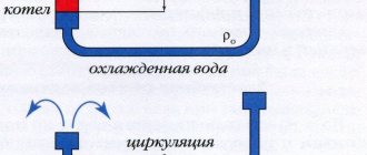
The pipe is laid from the heat source and returns to it, forming a ring circuit. The system functions as follows: the water heated in the boiler immediately goes up a vertical pipe, thereby creating pressure in the network.
When using a single-pipe water heating system in a two-story house, the coolant from the vertical pipe diverges along the contours. In one-story houses, this riser drops again to floor level, forming the so-called accelerating manifold. Only after this the pipe runs horizontally around the perimeter of the building, where the batteries are connected to it, and then returns back to the boiler. The features of such a system are:
- the flow area of the main pipe is unchanged throughout its entire length;
- Each subsequent heating device receives water at a lower temperature than the previous one. The reason is clear - the cooled coolant from the first battery is mixed into the common collector, reducing the temperature of the water passing through it;
- this feature stems from the previous one. To increase heat transfer, each subsequent device must have greater power, that is, the number of sections must be increased from battery to battery.
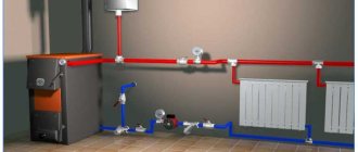
In most cases, a forced impulse is used to move the coolant through the pipeline network in a private house, that is, a circulation pump is installed. Then the system operates stably and more efficiently, although the organization of natural circulation is also possible. This is where the vertical accelerating manifold, whose height is maintained at least 2 m from the floor, will play its role. We should not forget that for normal gravity flow operation, you need to install an atmospheric expansion tank above the highest point of the system, ideally in the attic of the house.
The picture above shows what a single-pipe natural circulation heating system looks like in a one-story house. An expansion tank communicating with the atmosphere is installed under the ceiling (if height allows) or in the attic space and connected to the accelerating manifold. But such schemes do not work very well, since the temperature difference in the supply and return pipelines is small. To create good circulation, a pump is installed in the circuit, as in the figure below:
Now the expansion tank can be taken of the membrane type, since the system no longer requires communication with the atmosphere; excess pressure in it is created by a circulation pump. However, the presence of an accelerating manifold is necessary; here it has an additional function. It consists of maintaining the coolant level in radiators using the principle of communicating vessels. And, of course, it promotes better water circulation.
Connection
In double-circuit heating, one of three methods of connecting batteries is used: one-sided, diagonal or bottom. The best method is considered to be a diagonal connection. This way you can achieve maximum heat transfer from heating equipment (up to 98% of the nominal value).
The general diagram of pipe routing and connection of heating devices, boiler and shut-off devices for a one- or two-story house may look like this:
- Despite all the differences between the methods of connecting batteries, they are all used in practice, but with different tasks. In particular, the connection using the bottom method is not very productive, but it is a good option if the pipe needs to be placed under the floors.
- Hidden pipeline installation can also be used in one-sided and diagonal schemes; however, in these cases, large sections of the pipeline will remain visible, which can only be hidden under wall cladding.
- Connecting side-type batteries is practiced when the number of sections is limited to 15 elements - there is almost no heat loss in this case.
Options for single-pipe heating systems
There are natural and forced types of circulation; the scheme can also be divided by type:
- Heat source. These can be solid fuel, gas, or electric boilers.
- For heat-emitting devices, such as radiators or a heated floor circuit.
- According to the transportation device. If the coolant flows by gravity, an accelerating section of movement is required; if forced circulation is installed, a pump is installed.
- Depending on the equipment for compensating excess pressure. Expansion tanks of open or closed type are used.
Also taken into account are the types of pipes based on the material of manufacture and the types of water fittings.
Schemes with natural and forced circulation
Natural circulation means that the coolant is transported through the pipe by gravity, forced circulation - using a pump. The first option requires the installation of pipelines with a certain slope to ensure water flow. An acceleration section is also needed to obtain the required pressure, which moves the liquid. The acceleration section is a vertical pipe extending from the boiler. The coolant rises through the pipe, then flows down through a pipeline connected to the pipe, filling the entire heating line and radiators.
If a single-pipe gravity heating scheme is carried out with an upper distribution for 2-storey buildings, the supply pipe serves as the acceleration section, only it rises to the required level. When installing a single-circuit system in a one-story building with horizontal wiring, you need an accelerating manifold with a height of at least 150 cm from the level of the first installed radiator.
Gravity flow schemes depend on the number of turns - the more there are, the more difficult it is to transport the carrier, so it is recommended to make no more than 2 turns along the entire highway. Also, the gravitational type of transportation creates problems with warming up the last heating device - cooling water does not warm up the battery well, so the number of sections has to be increased.
It will help to install a pump that can be placed at any turn in the highway. The operation of the pump eliminates all the disadvantages of a single-circuit circuit, accelerates the movement of the coolant, and guarantees the passage of liquid through any turns. Before installing the pump, you need to decide on the zone - despite the ability to install it at any point, the interaction of rubber parts with hot water is taken into account, which reduces the service life of the device. Therefore, it is recommended to install pumps on the carrier return flow pipeline, where low-temperature water circulates.
When choosing a scheme, you should take into account the advantages of forced ventilation:
- simplified implementation of complex heating schemes with turns, raising the coolant to the 2nd floor, attic;
- no need to buy pipes of different diameters;
- there is no need to calculate the angle of inclination of each section of the pipeline.
There are also disadvantages - dependence on power supply, the possibility of clogging of the device and the presence of maintenance costs (payment of electricity bills).
Open and closed systems
Schemes differ according to the type of expansion tank, which is mounted with the system. If it is a closed container, the system is closed; if there is no lid, it is open. The tank is installed at the highest point of the system. In sealed tanks there is an outlet for draining excess water or the internal space is divided by an expansion-type membrane - when there is excess liquid, the gas in one half is compressed, the membrane is extended, as soon as the volume of liquid is normalized, the membrane returns to its original position and provides the required pressure. The closed system is very easy to install and use.
An open tank is also placed at the highest point of the diagram, but the tank does not have a lid, so interaction with oxygen entering the pipes is possible - increasing the risk of airing. The advantage of using an open system is that there is no need to monitor the pressure and the possibility of making an expansion tank from scrap material. Users note a number of other disadvantages - water needs to be added to the tank, antifreeze cannot be used (the coolant will evaporate, and its vapors are poisonous), oxygen in the coolant wears out the pipes faster.
How to work in EXCEL
Using Excel tables is very convenient, since the results of hydraulic calculations are always reduced to tabular form. It is enough to determine the sequence of actions and prepare exact formulas.
Entering initial data
Select a cell and enter a value. All other information is simply taken into account.
- the D15 value is recalculated in liters, this makes it easier to perceive the flow rate;
- cell D16 - add formatting according to the condition: “If v does not fall within the range of 0.25...1.5 m/s, then the cell background is red/the font is white.”
For pipelines with a difference in inlet and outlet heights, static pressure is added to the results: 1 kg/cm2 per 10 m.
Registration of results
The author's color scheme carries a functional load:
- Light turquoise cells contain the original data - they can be changed.
- Pale green cells are entered constants or data that is little subject to change.
- Yellow cells are auxiliary preliminary calculations.
- Light yellow cells—calculation results.
- Fonts: blue - original data;
- black - intermediate/non-main results;
- red - the main and final results of the hydraulic calculation.
Results in Excel table
Example from Alexander Vorobyov
An example of a simple hydraulic calculation in Excel for a horizontal pipeline section.
- pipe length 100 meters;
- ø108 mm;
- wall thickness 4 mm.
Table of local resistance calculation results
By complicating calculations in Excel step by step, you better master the theory and partially save on design work. Thanks to a competent approach, your heating system will become optimal in terms of costs and heat transfer.
Sequence of actions when installing water heating with two-pipe bottom wiring
It all starts with the choice of energy resource. If you use a gas boiler as the main one in the same scheme, and an electric or solid fuel boiler as a backup, then you can make the heating system energy-independent.
Next, you should contact the competent authority to develop and approve the project. Only after completing all the necessary documentation and purchasing equipment and consumables does the installation of the heating system begin.
Boiler room equipment
The boiler room should be spacious enough, with a high ceiling and good ventilation. Sections of walls and floors located in the immediate vicinity of the boiler are lined with fireproof materials.
The boiler is installed according to the operating instructions. The chimney is led out into the street through a special opening.
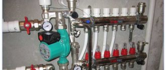
Manifold cabinet
This element is a compartment within which the pump, distribution manifold, regulators and meters will be located.
Pipe installation
The pipes are installed as straight as possible, without bends. If necessary, holes are made in the walls, which are subsequently carefully covered with cement mortar. To connect pipes, welding (metal) or a special iron (polypropylene) is used.
Battery Installation
Heating elements are located under the window sill. The installation requirements for the wall, floor and window sill are the same as for installing a single-pipe system. The length of the radiator (number of sections) should, if possible, correspond to the width of the window opening. Temperature regulator valves are installed at the coolant inlet and outlet areas.
The final stage of installation of water heating with bottom wiring is crimping. The first start-up of the boiler is carried out only in the presence of employees of the relevant service.
Analysis of calculations using a specific example
The house for which we will determine the load on the heating system has double-glazed windows (K1 = 1), foam concrete walls with increased thermal insulation (K2 = 1), three of which go outside (K5 = 1.22). The window area is 23% of the floor area (K3=1.1), it is about 15C below zero outside (K4=0.9). The attic of the house is cold (K6=1), the height of the rooms is 3 meters (K7=1.05). The total area is 135m2.
The initial data is known, so then everything is like in school: we substitute numbers into the formula and get the answer:
Fri = 135*100*1*1*1.1*0.9*1.22*1*1.05=17120.565 (Watt) or Fri=17.1206 kW
Mk=1.2*17.1206=20.54472 (kW).
Load and heat loss calculations can be done independently and quickly enough. You just need to spend a couple of hours putting the source data in order, and then just substitute the values into the formulas. The numbers you receive as a result will help you decide on the choice of boiler and radiators.
Operating principle of a single-pipe heating system
The operation of a single-pipe heating system follows fairly simple principles. There is only one closed pipeline through which the coolant circulates. Passing through the boiler, the medium heats up, and passing through the radiators imparts this heat to them, after which, cooled, it again enters the boiler.
There is also only one riser in a single-pipe system, and its location depends on the type of building. So, for one-story private houses a horizontal scheme is best suited, while for multi-story buildings - a vertical one.
To improve the efficiency of a single-pipe system, several improvements can be made. For example, install bypasses - special elements that are pipe sections connecting the forward and return radiator pipes.
This solution makes it possible to connect thermostats to the radiator that can control the temperature of each heating element, or completely disconnect them from the system. Another advantage of bypasses is that they allow you to replace or repair individual heating elements without shutting down the entire system.
Installation features
In order for the heating system to provide warmth to the owners of the house for many years, during the installation process it is worth adhering to the following sequence of actions:
- According to the developed project, the boiler is installed.
- The pipeline is being installed. In places where the project provides for the installation of radiators and bypasses, tees are installed.
- If the system operates on the principle of natural circulation, it is necessary to ensure a slope of 3-5 cm per meter of length. For a forced circulation circuit, a slope of 1 cm per meter of length will be sufficient.
- For systems with forced circulation, a circulation pump is installed. It is worth considering that the device is not designed for operation at high temperatures, so it would be better to install it near the entrance of the return pipe to the boiler. In addition, the pump must be connected to the electrical network.
- Installation of expansion tank. An open type tank should be located at the highest point of the system, a closed type - in any convenient place (most often it is mounted near the boiler).
- Installation of heating radiators. They weigh a lot (especially when filled with water), so they are secured using special brackets, which are usually included in the kit. Installation is most often carried out under window openings.
- Additional devices are being installed - Mayevsky taps, plugs, shut-off devices.
- The final stage is testing the finished system, for which water or air is supplied to it under pressure. If the tests do not reveal problem areas, the system is ready for operation.
Advantages
For private houses with a small area, a single-pipe heating system looks more preferable due to its following advantages:
- Ease of drafting.
- Ease of installation of the system.
- Reducing costs for the purchase of materials and equipment.
- Steady hydrodynamics.
- Safety of coolant circulation, which occurs naturally.
Flaws
There are also a number of disadvantages that owners of single-pipe heating systems will have to put up with:
- Difficulty in correcting errors made at the design stage in a commissioned circuit.
- Uneven heating of heating elements located at different distances from the boiler.
- Close interdependence of elements.
- High hydrodynamic resistance.
- Impossibility of adjusting coolant flow.
- Relatively large heat losses.
- Limited number of radiators that can be placed on one riser.
(no votes yet)
Factors affecting radiator efficiency
The main requirements for a heating system are, of course, its efficiency and economy. Therefore, its design must be approached thoughtfully so as not to miss all sorts of subtleties and features of a particular living space. If you do not have sufficient skills to create a competent project, it is better to entrust this work to specialists who have already proven themselves and have positive feedback from clients. You should not rely on the advice of friends who recommend certain methods of connecting radiators, since in each specific case the initial conditions will be different. Simply put, what suits one person may not necessarily suit another.
However, if you still want to install pipes to heating radiators yourself, pay attention to the following factors:
- the size of radiators and their thermal power;
- placement of heating appliances inside the house;
- connection diagram.
The modern consumer has a variety of heating appliance models to choose from - these include wall-mounted radiators made of various materials, and baseboard or floor convectors. The difference between them is not only in size and appearance, but also in the methods of liner, as well as the degree of heat transfer. All these factors will influence the choice of options for connecting heating radiators.
Depending on the size of the heated room, the presence or absence of an insulating layer on the external walls of the building, power, as well as the type of connection recommended by the radiator manufacturer, the number and dimensions of such devices will vary.
To direct the thermal energy from the radiator into the room, it is advisable to attach a special reflective screen between the device and the wall. Such a screen can be made from any heat-reflecting foil material - for example, penofol, isospan or any other.
Before connecting the radiator to the heating system, pay attention to some features of its installation:
- within the same residential premises, the level of placement of all batteries must be the same;
- the fins on convectors must be directed vertically;
- the middle of the radiator must coincide with the center point of the window or can be shifted 2 cm to the right or left;
- the total length of the battery should be 75% of the width of the window opening;
- the distance from the window sill to the radiator must be at least 5 cm, and there must be at least a 6 cm gap between the device and the floor. It is best to leave 10-12 cm.
There are often cases when apartment owners assemble and connect a heating system, following the recommendations of friends. In this case, the result turns out to be much worse than expected. This means that errors were made during the installation process, the power of the devices is not enough to heat a particular room, or the scheme for connecting the heating pipes to the radiators is inappropriate for a given house.
A few additional tips
Longevity is largely influenced by the materials from which the main parts are made. Preference should be given to pumps made of stainless steel, bronze and brass. Pay attention to what pressure in the system the device is designed for.
Although, as a rule, there are no difficulties with this (10 atm is a good indicator). It is better to install the pump where the temperature is minimal - before entering the boiler. It is important to install a filter at the entrance. It is advisable to position the pump so that it “sucks” water from the expander. This means that the order in the direction of water movement will be as follows: expansion tank, pump, boiler.
Conclusion
So, in order for the circulation pump to work for a long time and conscientiously, you need to calculate its two main parameters (pressure and productivity).
You should not strive to comprehend complex engineering mathematics.
At home, an approximate calculation will be enough. All resulting fractional numbers are rounded up.
Number of speeds
To control (switch gears), a special lever on the unit body is used. There are models that are equipped with a temperature sensor, which allows you to fully automate the process. To do this, you do not need to manually switch speeds; the pump will do this depending on the room temperature.
This technique is one of several that can be used to calculate pump power for a specific heating system. Specialists in this field also use other calculation methods that allow them to select equipment based on power and pressure created.
Many owners of private houses may not try to calculate the power of the circulation pump for heating, since when purchasing equipment, as a rule, specialist assistance is offered directly from the manufacturer or a company that has entered into an agreement with the store.
When choosing pumping equipment, it should be taken into account that the necessary data for carrying out calculations must be taken from the maximum that the heating system can, in principle, experience. In reality, the load on the pump will be less, so the equipment will never experience overload, which will allow it to work for a long time
But there are also disadvantages - higher electricity bills.
But on the other hand, if you choose a pump with less power than required, then this will not affect the operation of the system in any way, that is, it will operate normally, but the unit will fail faster. Although your electricity bill will also be lower.
There is one more parameter by which you should choose circulation pumps. You may notice that in the assortment of stores there are often devices with the same power, but with different dimensions.
You can calculate the heating pump correctly, taking into account the following factors:
- 1. To install equipment on conventional pipelines, mixers and bypasses, you need to select units with a length of 180 mm. Small devices 130 mm long are installed in hard-to-reach places or inside heat generators.
- 2. The diameter of the supercharger pipes should be selected depending on the cross-section of the main circuit pipes. At the same time, it is possible to increase this indicator, but it is strictly forbidden to decrease it. Therefore, if the diameter of the main circuit pipes is 22 mm, then the pump pipes should be 22 mm and above.
- 3. Equipment with a pipe diameter of 32 mm can be used, for example, in heating systems with natural circulation for its modernization.