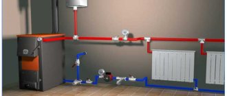
For heating individual residential buildings, single-pipe and two-pipe systems with natural or forced circulation of coolant are widely used. Each of them has its own area of application and certain advantages and disadvantages - if single-pipe decoupling schemes work well with radiator heat exchangers, then a collector heating system is indispensable when installing multi-circuit heated floors.
The collector (parallel) junction is widely used in heating schemes of individual houses for heating rooms and is the most expensive, its cost is comparable to a two-pipe distribution system. However, every house cannot do without such a scheme, in which a large number of heat exchange radiator circuits and heated floors are used to supply heat to the premises.
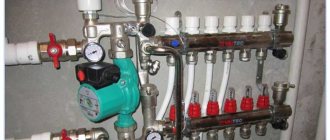
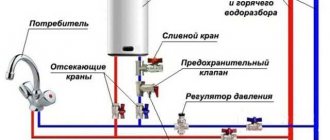
Rice. 1 Collector heating system for a private house - installation example
What is a collector heating system
In heating, a collector is an element of water supply fittings designed to distribute through branches, collect and mix coolant from many parallel heat exchange circuits.
The collector circuit ensures the simultaneous supply of coolant to the circuits of underfloor heating and heating radiators (their maximum number in one comb reaches 12) with the same pressure and temperature, which can be set by a thermostat. The collector line differs from single-pipe and two-pipe systems in that it approaches the heating radiators from below.
Boiler connection
The most effective source of heating is considered to be connecting a heated floor to a gas boiler and for this reason it is better not to consider other types of heating units. This statement is explained by the high cost of electricity and the ability to independently regulate the temperature regime in the system.
After the location of the collector has been determined and its installation has been completed, you need to install the heating device and begin connecting the heated floor to the boiler.
Operating principle of the collector system
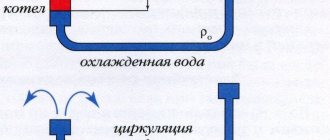
The collector system operates on the following principle: the coolant heated by the boiler, using a circulation electric pump installed between the supply and return lines, enters the collector distribution comb, to the output fittings of which the heating circuits are connected. The overall temperature of the coolant in all circuits is set by a thermostat located on the inlet fitting of the supply comb, and each outlet to the loop is equipped with a flow meter, with the help of which the volume of coolant flowing through the circuit is manually set.
After passing through the circuits, the cooled coolant enters the return line and is pushed by an electric pump to the boiler, in which it is heated. Circulating in a circle, the heated liquid is returned to the supply manifold, which distributes it over individual heating circuits.
In most designs, return line distribution units are equipped with shut-off valves - this allows the installation of electric servo drives on them to automatically regulate the flow passing through the circuits.
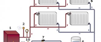
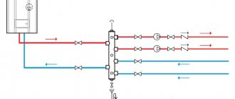
Rice. 2 The principle of collector heating
Advantages and disadvantages of radiant heating systems
Positive sides
The main advantage of the beam scheme is ease of use.
Special equipment makes control of the climate network as ergonomic and convenient as possible:
- You can set the temperature of each heating radiator in the house without leaving the manifold cabinet. In addition, if necessary, you can completely shut off the water supply to any element of the system without disrupting the functionality of the entire heating network.
- Each pair of pipes connects the collector to only one radiator. Therefore, you can use small-diameter pipelines that can be easily disguised under the floor covering. Among other things, this allows you to partially warm the floor surface.
Radiant heating system pipes are laid before the floor is poured
- Thanks to the use of special devices (the so-called hydraulic arrows - collectors with a large diameter), it is possible to create several heating zones in the house with different coolant temperatures.
In this case, a short circuit is organized between the supply and return pipes. Heated water constantly circulates in the hydraulic arrow, and it can be taken at different distances (the temperature will depend on this).
Negative sides
To complete the picture, we should also talk about the disadvantages of using a radial heating system.
It is because of them that, despite all the advantages, it is not very widespread:
- Greatly increased flow of supply and discharge pipes. The more spacious the house and the more complex the geometry of the rooms, the more parts will be needed. In addition, the complexity of installation increases, which cannot but affect the estimated cost of construction.
A radiant heating system requires the use of a huge number of pipes and collectors
- The need for hidden installation. While a traditional tee system can be installed along walls, you won’t be able to place a huge number of pipes this way. They must be hidden under the floor. You can also wall it up in walls, but in this case the consumption of material will increase even more.
- No joints. When designing pipelines, it is imperative to ensure that the pipe under the floor does not contain a single joint. Breaks most often occur in this place, and the cost of repairing the breakdown will be far from low and very labor-intensive.
- If the system design includes several circuits with different coolant temperatures, then each of them must be equipped with a circulation pump.
What is included in the collector system
The collector is the most critical and complex device in the heating system; a typical device for connecting underfloor heating circuits consists of the following main components:
- The supply comb is a horizontal pipe with bends for connecting heating circuits; depending on the design, it is located above or below the return manifold.
- Reverse comb - the product is a mirror image of the previous part, has similar dimensions of the main channel and the number of inlet fittings.
- Flow meters - elements are installed in the outlets of the supply manifold, have a transparent body, the walls of which are marked with divisions with a digital designation. A rod with an indicator head placed inside the housing indicates the volume of coolant passing through the circuit.
- Shut-off valves - usually the elements are placed in a reverse comb and closed with continuously adjustable caps.
- Air vents - mounted on the supply and outlet combs, with the help of devices they bleed air from the manifold strips in automatic or manual mode.
- The thermostat is a device with a remote sensor mounted on a flexible tube; it is placed at the entrance to the manifold, where it provides the ability to regulate the temperature of the coolant, which in a heated floor circuit should not exceed 55 C.
Rice. 3 Collector - structural design and main components
- Electric circulation pump - included in some models, the device ensures the movement of coolant through the pipeline of the collector system with a certain pressure. The unit is additionally installed with an electric pump, which ensures circulation throughout the heating circuit of the entire house.
- Digital temperature sensors - installed in separate modifications; measuring instruments in the supply and return lines allow you to control the temperature. This helps to optimally configure the loop for the best heat transfer and efficiency, which is observed with a difference of 10 C.
- Thermal sensor - some collector circuits include a thermostatic sensor, which, when the temperature of the coolant exceeds 55 C, opens the power circuit of the compression electric pump.
- Bypass - sometimes a jumper is installed in the collector system connecting the supply and outlet combs; the element is designed to mix the cooled coolant with the hot water entering the collector inlet.
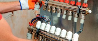
Rice. 4 Different types of combs
Diagram of a heated floor with a three-way valve
Mixing fluid flows, which a thermostatic mixing valve allows, makes it possible to direct flows with a stable, standard temperature into the underfloor heating system. This operation is performed automatically. For mixing that takes place inside the device, already cooled liquid from the “return” is added to the hot water.
- Operation occurs in the following sequence:
- hot water flows to the collector included in the underfloor heating system;
- when passing through the thermo-mixing valve, the degree of heating of the liquid is determined;
- if the water temperature is higher than the set one, then a passage opens into which the cooled liquid enters;
- two flows are mixed inside;
- after reaching the desired value, the cold water passage closes.
The mixing pump can be replaced with a three-way mixer, which performs the same function, only without a pump (used when there is good circulation that does not require an additional pump). The installation of a three-way mixer is carried out in the same place as the pumping and mixing unit, i.e. at the outlet of the return manifold.
On the one hand, the collectors are connected to pipes from heating equipment, and on the other hand, a splitter must be installed on each collector. An air vent is connected to the top side of the splitter. A drain valve is installed on the bottom side of the splitter.
Among the disadvantages of three-way valves, there is the possibility of sudden temperature jumps that occur during the start-up of heated water, which negatively affects the condition of the pipeline.
This faucet, made of brass, has three strokes in its design, which determine the use of different methods of mixing liquid flows, depending on which there are three types of three-way valves.
Valve with the thermostat function required for heated floors. Such a device not only regulates the intensity of the mixed flows, but also ensures that the system maintains a given temperature.
This function is facilitated by the presence of a heat-sensitive element, which, by detecting the degree of heating of both flows entering the tap, changes the cross-section of the holes.
The three-way thermostatic valve of the second type is distinguished by the fact that it provides regulation of the supply intensity of only the hot flow. The package includes a thermal head with a remote sensor. You can also select a mixing valve from the assortment of three-way models that does not automatically maintain the set temperature.
- Depending on the direction of flow, the thermostatic valve is available in two models:
- T-shaped or symmetrical design. With this connection, hot and cold water enters through the side holes, and after mixing, the liquid flows out through the central passage.
- L-shaped or asymmetrical design. In this case, hot water comes from one side, and cold water from below. Subsequently, the mixed flow exits from the second side passage.
- Considering the mixing unit, we can distinguish the following components in it:
- Check Valve;
- temperature sensor;
- circulation pump;
- three-way mixing valve.
The connection diagram includes a circulation pump mounted on the supply. Then a temperature sensor is installed, which is necessary to determine the degree of heating of the incoming water. After this comes the thermostatic valve.
A check valve with an outlet is mounted on the “return”, which is connected to a pipe with circulating cooled liquid directed to the mixing valve.
- With a similar connection diagram, the coolant moves along the following route.
- Pumping hot water using a circulation pump into the equipped heated floor system. The coolant temperature can reach 80°C.
- Mixing with cold water through a three-way valve. As a result, the desired temperature is achieved.
- Distribution of coolant through underfloor heating pipes.
- The return of the cooled water to the “return”, from where it is taken into the three-way valve for subsequent mixing with the hot liquid.
With such a connection, the temperature sensor regulates the degree of heating of the water entering the water circuit.
There are other ways to control. The most ineffective is the manual method, when you need to change the flow by turning the handle. There is a control option using a servo drive, commands to which are received from the controller in accordance with signals received from sensors.
The thermostatic tap plays an important role when installing a water heated floor. By preventing the coolant entering the pipes from overheating, it saves fuel. In addition, safety is ensured during the operation of a rather complex heating system and the trouble-free service life is extended.
Selection criteria
When choosing a mixing valve, it is advisable to focus on several indicators.
- Room area.
For small rooms - bathroom, toilet, it is not always recommended to purchase a more expensive thermo-mixing valve, since it is enough to install a familiar valve. Large rooms with warm water floors will require mixers that automatically regulate the temperature of the heating fluid.
- Cross-sectional dimensions.
This indicator must be taken into account when selecting a thermostatic valve, ensuring precise connection to the heating system. If there is no device with the required diameter in the assortment offered in the store, then special adapters are purchased.
- Possibility of obtaining an automatic operating mode.
- Bandwidth.
This parameter is calculated at the design stage of the heated floor. Based on the obtained values, a mixing valve is selected that can withstand the required load.
Feed and return manifold comb device
Combs are one of the main elements of the collector circuit; their main function is to distribute the coolant flow along the heating circuits. The element has a different design for lines of connected radiators and heated floors, the maximum number of involved circuits per collector does not exceed 12.
In relation to the diameters of the outlet fittings, the comb has a large cross-section (1.1 1/2 inches versus 3/4) and is connected to the main line through an end connection with elements of plumbing fittings. Typically, the pipeline is connected to the outlet fittings using compression fittings (Eurocones) - this method can be used to connect pipes made of cross-linked and heat-resistant polyethylene, metal-plastic, most often used in manifold heating systems. Combs are made of stainless steel, brass, plastic, some modifications are assembled from individual links.
Operating principle of the distributor
The main purpose of the distribution manifold is to evenly distribute heat flows coming from the main line along the system contours and, through circulation, return the cooled liquid to the boiler.
In this case, individual branches of the system connected to the collector become independent of each other.
The device is an intermediate distribution unit, the key elements of which are two interconnected parts:
- supply comb - responsible for supplying coolant;
- reverse - performs the function of removing the cooled coolant to the heat generator.
Together they form a collector group. From each comb there are several leads for connecting circuits leading to heating devices.
Each outlet of the device can be equipped with outlet valves and a shut-off or control valve.
Their presence makes it possible to regulate the pressure inside each circuit and, if it is necessary to disconnect a branch for repairs, for example, shut off the coolant flow.
To increase the performance of the system and be able to control all heating processes in each room of the heated house, the housing of the distribution comb is also used as a platform for installation:
- air release valves;
- drain valves;
- flow meters;
- heat meters.
The operating principle of the collector system is quite simple. The liquid heated by the heat generator enters the supply comb.
Inside the intermediate assembly unit, the speed of fluid movement slows down due to the increased internal diameter of the device; it is redistributed between all outlets.
The number of pins on the distributor can be any, and if necessary, the design can always be expanded with additional taps
Knowing the coolant flow rate equal to the power of the heat generator and the speed of water movement, it is easy to find the required cross-sectional area. You just need to first convert the liters into a convenient unit for calculations, mm 3 .
Through connecting pipes, the cross-section of which is smaller than the diameter of the pipe of the collector unit, the coolant enters separately laid circuits and moves to radiators or to heated floor grids.
Thanks to this distribution, each element is properly heated, supplied with a coolant of equal temperature.
The internal diameter of the collector is determined by calculation so that the speed of movement of the coolant inside it is no more than 0.7 m/s
Having reached the battery and given off the heat received during heating, the liquid is directed through another pipe in the opposite direction to the distribution block. There it enters the return comb, from where it is redirected to the heat generator.
For a country cottage, a system using a collector is rightfully considered the most effective and reliable.
The only thing that can stop a zealous owner is the cost. After all, installing such a system will cost more than installing a conventional tee-type system.
This design solution, which involves the installation of separate supply pipes, creates conditions for uniform heating of the radiators
Technical characteristics of collectors, their pros and cons
The collector is used in water radiator and underfloor heating systems, being a distribution unit for various circuits; its typical characteristics for brass or stainless steel have the following indicators:
- The standard nominal diameter of dies is 1″ or 1 1/2″ inches.
- Typical outside size of outlet fittings is 3/4″ or 1/2″ inch.
- The number of output fittings (connected circuits) is from 3 to 12.
- Connecting pipes using a Euroconus compression connector.
- Typical operating pressure in a brass system is up to 10 bar.
- The maximum temperature of the working environment is +120º C.
- The maximum length of the circuit is no more than 90 meters (depending on the diameter and material of the pipes), and their maximum deviations in length should not exceed 30%.
The industry produces two types of collectors with significant design differences - for heating radiators and heated floors, the latter always contain a mixing unit for mixing water from the return line.
Rice. 5 Wiring diagram for radiator manifold heating systems
Advantages
The distribution manifold has the following features when operating in a thermal system:
- Allows you to use a large number of independent circuits of heated floors and radiators (up to 12) in heating, each of which can always be turned off without stopping the heating and the operation of other heat exchangers.
- Ensures constant media parameters in all circuits and adjusts the supply volume (pressure and temperature) in each of them - this increases the comfort of heating use.
- A significant advantage of the manifold comb is the ability to install electric servos in it, which block the flow with valves depending on the readings of the sensor connected to them; they can be installed anywhere - in a room, on a radiator or near the surface of a heated floor. Thus, automatic regulation of the temperature of the heating circuits is achieved and energy resources are saved.
- The system uses flexible small-diameter heating pipes made of relatively inexpensive polymer materials, having a small cross-section and secretly passing under the floors; the coolant is supplied to the upper or lower floors without risers. This design increases the aesthetic appearance of housing and minimizes financial costs.
- It is quite easy to increase the length of the collector by attaching additional links with output fittings to connect new circuits.
- The reliability of the scheme is quite high due to the minimum number of hidden connections, and when installing heated floors they are completely absent - a pipe of any length is connected to the inlet and outlet of the collector at points of direct visibility and convenient access. The same can be said about radiators, which are connected through easily accessible fittings from below, not far from the floor surface.
- High maintainability is ensured by the ability to disconnect any branch for repair or replacement of devices without disrupting the operation of other circuits.
Rice. 6 Installation of supply and return pipelines in a collector system - example
Flaws
The disadvantages of collectors include their following parameters:
- The cost of a factory-made collector assembly from trusted manufacturers made of corrosion-resistant metals is quite high and can reach 300 USD, which is a fairly significant amount for the average consumer. Costs can be reduced by using lower quality and reliable plastic models, the price of which reaches 50 USD.
- For efficient heating, the length of all circuits is kept as minimal as possible; for this purpose, radial wiring is used and they try to place the collector as close to the center of the house as possible in order to achieve the same length of all circuits as possible. In practice, placing the collector in the center of the house is not always possible for technical reasons; moreover, such an installation spoils the aesthetics of the appearance of the room with the installed distribution system.
- Assembling the distribution collector system of a private house with your own hands by an unprepared homeowner is quite problematic; installation and configuration work can only be carried out by highly qualified specialists with extensive experience. Paying for the services of professionals will require significant financial resources, which is difficult for the average person.
- As noted above, the pipes of all circuits pass under the floor, that is, you will have to screed not only in rooms with heated floors, but also on all floors in the house to level the floor level and hide the pipes that fit the circuits. Carrying out these works will also require significant financial expenses not only for wages of workers, but also for materials (thermal insulation, mesh, screed mortar).
- The collector circuit is not gravity-fed, that is, in the absence of electricity, the operation of the circulation electric pump in the collector unit stops, and the movement of the coolant flow stops along with the heating of the premises.
How to install?
Before installing a water distribution unit for cold and hot water supply, give an accurate answer to the following questions and consider the following points:
- How many water consumers are there on site? The number of collector outlets should be the same or slightly greater than the number of consumers. Excess branches are closed with plugs.
- What type of pipes will be used to install the water supply? It is necessary to purchase devices designed specifically for pipes made of the selected material.
- Estimate in advance the position of all engineering elements in the space of the plumbing cabinet (you can make markings on the wall). Please note that a water meter and a water filter are installed in front of the distribution comb. The convenient location of all devices facilitates maintenance and repair work.
- Get reliable fastening - a poorly secured distribution unit can lead to depressurization of connections and damage to the pipeline.
- Before installation, make sure that you have all the necessary consumables on hand: sealing material, gaskets, adapters.
Installation of the water distribution unit occurs in the following sequence:
- Install the inlet shut-off valves on the water supply riser.
- Install the meter, filter and check valve.
- Connect the manifold and securely fix it to the wall
- Install a water supply to each consumer. Secure the pipes with fasteners.
This operating algorithm will allow you to avoid errors. Regardless of whether the collector is needed for water supply or heating, its installation is the same. Such wiring requires more time, skill and money, but pays off quickly and provides comfort in further use. Collectors are appropriate not only in cottages and large houses, but also in apartments.
Collector heating system - general principles for designing wiring diagrams
Correct design and calculations of the collector system can only be done by qualified specialists; when performing design work, they must be guided by the following rules:
- To determine the length of the circuits, parameters of heating radiators, coolant temperatures, it is necessary to calculate heat losses in the main line and circuits. This operation will allow you to determine the optimal dimensions of heating devices (the number of their sections) and the lengths of the contours of heated floors, otherwise the rooms will be too hot or cold during normal operation and additional adjustments will be required, reducing the efficiency and performance of the system.
- It is prohibited to connect heating radiators to collectors for heated floors - they have different hydraulic resistance and operating temperature conditions (coolant temperature 40 - 55º C for heated floors and 60 - 80º C for heating radiators).
- The permissible temperature difference between the water supply line and the return line is 5 - 15º C, the optimal difference is 10º C (55/45, 50/40, 45/35, 40/30 degrees).
- The temperature of the floor surface for living rooms and offices is 21 - 27º C, in living rooms, corridors, hallways - 29 - 30º C, in bathrooms and swimming pools - 33º C, in home workshops with active physical activity - about 17º C.
- The distance between adjacent turns of pipes in the living rooms of a private house lies in the range of 150 - 300 mm, it is excellent for different zones and changes in increments of 50 mm:
- For edge zones and near windows, the interpipe distance is 100 - 150 mm.
- In the central zone of medium and large rooms, the standard inter-turn distance is about 200 mm.
- In bathrooms, showers and bathrooms, a distance between hinges of 150 mm is used.
Rice. 8 Heat consumption of a cottage - calculation example
- The maximum loop length of large underfloor heating rings with a diameter of 3/4 inch (16 mm) should not exceed 70 - 90 meters, the value depends on the material of the pipes and increases with increasing diameter (for 20 mm pipes the permissible length is 120 meters.)
- The electric pump must have a rated power calculated mathematically; exceeding it leads to excessive noise, and a low value does not provide the optimal speed of coolant movement.
- According to building codes, the number of circuits connected to one comb should not exceed 8; the European standard allows the use of 12 branches.
- In underfloor heating manifolds, it is necessary to have mixing tees or bypass jumpers to ensure that the cooled coolant from the return line is mixed with the hot liquid entering the combs from the boiler. In the absence of such a device, the heated floor will overheat, causing discomfort among residents, increased wear or deformation of some types of pipelines.
Rice. 9 Design of a collector comb for heating radiators and its connection
What to consider when designing and installing
When carrying out planning and installation work, the following rules are followed:
- When pouring screed under heated floors, it is necessary to install damper gaps around the perimeter of the premises - this prevents deformation of the floor during thermal expansion of the screed and helps avoid the appearance of cracks.
- Also, the screed must have a thickness that ensures its uniform heating and heat retention for a certain time; usually the layer thickness is in the range of 30 - 50 mm. It should be taken into account that a thick layer will heat up for a long time and cool down slowly, while a thin layer, when heated quickly, retains heat for a short time - this will cause more frequent switching on and off of the equipment, and accordingly its increased wear.
- Under underfloor heating pipes, it is necessary to lay thermal insulation to prevent heat from escaping into the concrete slab; usually for these purposes, foil penofol (foamed polyethylene) is used, laid with an aluminum layer up to reflect thermal radiation.
- Before pouring the screed, coolant is supplied into the pipes with double pressure, which is released after it hardens - thus, the channels formed in the screed will not further compress the pipeline when it expands after filling with coolant.
- Supply pipes should not have butt joints under the screed; areas not related to the contours of radiators and heated floors should be placed in corrugated insulation to reduce heat loss.
- The floor covering of heated floors must have high thermal conductivity; the use of wood, linoleum, and carpets that interfere with heat transfer is excluded.
Rice. 10 Manifold wiring with hydraulic arrow - diagram
Principles of drawing up wiring diagrams
The optimal placement of the collector block is above the level of the heated floor; if it is heating a two-story dacha or cottage, it is more convenient to place it on the second floor in the center. In this case, all contours will have approximately the same length, in contrast to installing the block near external walls or in the corners of buildings.
- You might be interested: Do-it-yourself heating in a private house from polypropylene pipes
The most popular models
1. Oventrop Multidis SF.
An inch heating comb is designed to organize heating with a water heated floor. Made from tool steel, characterized by high wear resistance. Main characteristics:
- permissible pressure in the circuit – 6 bar;
- coolant temperature – +70 °C.
The series is produced with valve inserts M30x1.5, and can also be equipped with a flow meter for connecting circuits located in different rooms. A bonus from the manufacturer - soundproofed mounting clamps. The number of simultaneously serviced branches is from 2 to 12. The price, accordingly, is 5650-18800 rubles.
To work with high-temperature appliances, Oventrop suggests using a heating system distribution manifold made of Multidis SH stainless steel with a Mayevsky tap. The design can already withstand 10 bar at +95-100 °C, the comb throughput is 1-4 l/min. However, products with 2 circuits have slightly weaker performance. The cost of Oventrop SH hydraulic valves ranges from 2780-9980 rubles.
Plumbers: You'll pay up to 50% LESS on your water bills with this faucet attachment
- HKV – brass underfloor heating manifold. Maintains a pressure of 6 bar in the range of +80-95 °C. Rehau version D is additionally equipped with a rotameter and a tap for filling the system.
- HLV is a heating distribution comb designed for radiators, although its characteristics are identical to the description of HKV. The only difference is in the configuration: a Eurocone is already provided here and the possibility of a threaded clamp connection with pipes.
The manufacturer Rehau also offers to buy separate Rautitan combs with three outlets for pipeline installation using sliding sleeves.
Heating distribution manifold made of steel with anti-corrosion coating. It operates in systems with temperatures up to +110 °C at a pressure of 6 bar and is hidden in a special heat-insulating casing. The throughput of the comb channels is 3 m3/h. Here the choice of designs is not very rich: it is possible to connect only from 3 to 7 circuits. The cost of such hydraulic valves will range from 15,340 to 252,650 rubles.
Stainless steel manifolds are produced in an even more modest range - for 2 or 3 circuits. With the same characteristics, they can be purchased for 19,670-24,940 rubles. The most functional Meibes line is the RW series, which already comes complete with various connecting elements, thermostats and manual valves.
- F – a flow meter is built into the supply;
- BV – has quarter taps;
- C – provides for extension of the comb through a nipple connection.
Each Danfoss heating manifold allows a system pressure of 10 atm at an optimal temperature (+90 °C). The design of the brackets is interesting - they fix paired combs with a slight offset relative to each other for more convenient maintenance. Moreover, all valves are equipped with plastic heads with marked markings, which allows you to set their position manually without the use of tools. The price of Danfoss models, depending on the number of connected circuits and additional options, varies between 5170 - 31,390.
The heating manifold can be selected for a Eurocone with 1/2″ or 3/4″ outlets or with a metric threaded connection. Far combs can withstand pressure up to 10 atm at temperatures not exceeding +100 °C. But the number of outlet pipes is small: from 2 to 4, but the price is the lowest of all the products reviewed in our review (730-1700 rubles for an unpaired distributor).
Tips for choosing
Despite the apparent simplicity of the combs, they need to be selected based on several technical parameters:
1. Pressure in the system - this value determines what material the distribution manifold can be made from.
2. The throughput must be sufficient so that the connected heating circuits do not “starve” from a lack of coolant.
3. Energy consumption of the mixing unit - as a rule, it is determined by the total power of the circulation pumps.
4
Possibility of adding circuits - this parameter should be paid attention only when in the future it is planned to build additional objects that require heating
The number of pipes on the hydraulic distributor must correspond to the number of connected branches (heating devices). In some cases, it is better to install several collectors, for example, in a two-story house - one block on each level. It is also possible to install unpaired combs at different points: one on the supply, the other on the return.
Finally, experts and experienced installers in their reviews advise not to skimp on buying a good collector. In order for it to serve for a long time and not cause any problems, the name on the box must be known.
Manifolds for radiators and heated floors
The difference between a floor collector and a radiator collector is in the design associated with the difference in operating temperatures and the lower hydraulic resistance of the radiator elements. The design of the block for connecting underfloor heating is much more complex; it includes a large number of control water fittings and a circulation pump for multi-circuit systems.
The standard manifold block for household radiators has a simple design: it consists of supply and return manifolds of large cross-section, from which come fittings for connecting pipes going to the radiators. The device usually does not have any adjusting, tuning valves or other complex devices, so connecting and installing it does not cause difficulties for most homeowners. Heating radiators are connected to the unit through pipes running in the floor and connected from below at one point; to place a straight pipeline it is not necessary to make a screed; it can be laid in a groove cut or knocked out in the slab.
A typical collector block is a technically complex element with a large number of adjustments and settings; often a circular electric pump is installed in the system. When installing the block, you should distinguish between the forward and reverse feed combs; for convenience, they are marked with red and blue paints, respectively. Also, adjustable flow meters with a transparent cap and marked divisions indicating the volume of liquid passing through them are most often placed in a straight line; it is marked with an internal red indicator head.
Typically, the maximum value of the transmitted flow does not exceed 5 cubic meters per hour (corresponding to division 5 on the cap), the minimum mark is 0.5. If the indicator heads are in the upper part, then when the water flow passes through the supply comb, the indicator lowers and shows the volume of liquid passing through. Sometimes the heads are located at the bottom, in this case the flow moves in the opposite direction from the heating circuit to the comb and, accordingly, the flow meters are installed in the return flow bar.
If a circular electric pump is installed in the collector block, then its impeller directs the flow from the output comb to the supply housing - thus mixing cold water from the return line into the coolant heated by the boiler to lower its overall temperature.
The standard block provides space for the location of the thermostat sensor, there are exhaust valves for bleeding air in the supply and return combs, valves are installed in place of which there are seats for servos that perform automatic control of operating modes.
Rice. 11 Collector heating system for an individual house, Gidrostrelka - installation and connection diagram
- You might be interested in what the pressure in the heating system should be.
Why do you need a collector, principle of operation
The design of this plumbing fixture is very simple. Essentially, this is a piece of large diameter pipe equipped with threaded fittings for connecting the circuits of the water system. The length of the heating comb depends on the number of connections; the main line is usually connected to the end.
What happens in the collector, where water flows from 2...10 parallel branches:
- From several lines, a coolant with various parameters - temperature, flow rate, flow rate per unit of time - enters the collection pipeline.
- In a large flow section of the comb, the speed of water movement decreases and the hydraulic resistance decreases.
- Mixing in the main chamber, different flows acquire the same temperature and speed at the outlet.
Diagram of operation of the collector pipe for collecting coolant
So, the task of the collector is to collect the coolant, equalize its parameters and send it back to the boiler along the main line. You cannot do without a comb when you need to combine several lines with different water flow rates, hydraulic resistance and length into one pipeline. Try to connect such branches on tees - 2-3 circuits will immediately stop working normally.
The heating distribution manifold operates in a similar way, only in the opposite direction. Water from the boiler, flowing slowly through the main chamber, is distributed in the required quantity through secondary lines.
One bare pipe with branches is of little use without accompanying fittings - taps, valves and other elements. The assembled collector unit helps solve several important problems:
- regulate the amount of coolant in each branch, balance them among themselves;
- by mixing, reduce the temperature of the supplied water and maintain it at a given level;
- empty the system, bleed air;
- automatically control the microclimate of each room using room thermostats.
Hydraulic arrow and solar collector
A hydraulic arrow and a solar collector are devices that perform functions similar to plumbing combs - they collect media from several sources in one housing and distribute it along circuits for various purposes.
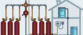
A hydraulic distributor is installed in cases where significant volumes of coolant are used for heating, associated with a large number of circuits and areas of heated premises. A boiler, a hydraulic accumulator, collectors of heating radiators and heated floors, a boiler, and pumping equipment are connected to the riser hydraulic connection with the installation of a circulation pump on each collector link.
The device is designed to stabilize pressure and equalize temperature in connected circuits and provides convenient connection of distribution nodes. A hydraulic arrow is a vertically (sometimes horizontal installation is used) located container (large-diameter pipe) of round or rectangular cross-section with welded side fittings, in the upper part of which there is a valve for venting, and at the bottom there is a tap for draining the coolant.
Rice. 12 Flat solar collector
Solar batteries are used in areas with a large number of sunny days a year; to save energy resources, solar collectors are used for additional heating of the coolant used for heating and other economic purposes.
If solar panels convert ultraviolet radiation into electrical energy, then solar collectors are designed to heat the coolant, which is air or liquid.
The simplest and most popular collector device in everyday life is designed and works as follows. A heat receiver is placed in a metal case under protective glass - a black plate with a pressed-in coil made of copper or aluminum, coated with a black absorbent; the solar radiation receiver is located on a layer of insulation. The cooled coolant moves along the coil using the circulation pump of the heating system and, after heating by solar radiation, enters the boiler.
The described system has high heat losses, so more expensive schemes use a pipeline covered with an absorbent layer and placed in a vacuum. Externally, the device resembles a series of glass flasks with evacuated air, inside of which heated copper pipes with refrigerant are placed, each pipe is connected to a distribution solar collector. In such systems, a special refrigerant with a low boiling point is used as a coolant; when heated, it turns into steam and transfers its energy to the medium flowing in the heat exchange manifold.
Purpose of the heating manifold
The absence of a distribution manifold in a water heating system can lead to the fact that water may flow unevenly into different circuits of the system. As a result, you will have a hot floor and cold radiators, or vice versa.
This may occur because several heating system circuits can be connected to one boiler outlet. The liquid flows unevenly through such connections, as a result of which part of the premises will not have enough heat. But the efficiency of the heat supply system depends on the amount of coolant passing through the pipes, the volume and speed of its movement.
pipes coming from the boiler
Some home owners try to solve this problem by installing additional pumps and control valves. But this only complicates the system and does not always lead to uniform distribution of the coolant.
How is the coolant distributed in a private house?
Let’s take, for example, a heating system for a private house with an area of 100 square meters. The device for heating water will be a wall-mounted gas boiler with one outlet pipe with a diameter of ¾ inches.
In our house we have two heating circuits and one circuit that heats water for domestic use with indirect heating. All circuits are built from pipes with a diameter of 1 inch. How to calculate and build an effective heat supply system?
First of all, we understand that the main reason for poor-quality heat supply is an elementary lack of coolant in the system. But the main reason for this shortage is excessively narrow distribution pipelines.
Thus, you can increase the efficiency of the thermal system, that is, increase the diameter of the distribution pipes in two ways:
heat flow distribution
- When using boilers with built-in pumps, a hydraulic arrow (flow distributor) is connected to them. In this case, each heat consumption circuit must have its own circulation pump. But such a device will only work in a small building. As the heated area increases, its efficiency and reliability drops sharply.
- The most reliable way is to connect a water distribution manifold to the heat source.
The most advanced type of distribution manifold is called camplanar. With its help, the problem of connecting pipes of different diameters and volumes of placed coolant is effectively solved.
distribution hydraulic manifold for 4 circuits
Let's look at how to create heat flow distribution systems with your own hands.
Features of installation of the collector system
Installation of heating systems is carried out before finishing work on laying floor and wall coverings; the pipeline running along the floor is tied to a strong metal mesh and filled with a screed located on the insulation layer.
Apartment house
The implementation of collector heating in a residential apartment building is practically not used in everyday life, this is primarily due to the presence of radiator heating in buildings, in which all rooms in the apartment are heated by radiators. Laying circuits for heating rooms through floors is associated with significant financial costs and is ineffective; moreover, a comb is not required for laying a small number and short length of loops. A significant factor that makes the installation of collector heating in an apartment building useless is the imbalance and violation of the temperature regime of the entire house system, as a result of which penalties and dismantling of the installed heated floor are possible.
Cottage
Collector combs are the main elements in organizing heating of country houses and cottages; they are usually placed in the wall of rooms located in the center of the house on each floor, connected to a riser built into them.
To do this, during the construction stage, a recess is placed in the wall in which the comb is placed; to improve the aesthetic appearance, a manifold cabinet with closing doors is placed in the place of insertion.
One circuit is used for each room; if there are several radiators in the room, they are connected in series using a single-pipe passing or pass-through circuit (Leningrad). Several small circuits are installed if the area of the premises is large and the maximum length of the pipeline does not ensure its coverage at a given pitch.
Rice. 14 Combined heating system
What are the principles used to draw up a wiring diagram?
In fact, there is no standard layout for the distribution of collector heating. Equipment is selected based on specific tasks. Experts say that using such a system for heating an apartment is not recommended. The fact is that it is difficult to independently implement a project in which only 2-3 risers are installed.
A prerequisite for connecting the entire system is the installation of all coolants to only one riser. To implement such a project, it is necessary to collect permitting documentation.
The fact is that when carrying out such a project, it will be necessary to solder the excess risers. As a result, the operation of the central heating system in a multi-storey building is disrupted.
During the design, it is necessary to take into account the following recommendations:
- Availability of air duct. To work, you will need to use an automated valve, which is placed in the supply and return areas of the manifold;
- Using an expansion tank. In this case, its volume indicators should be more than 3% than the relative volume of the entire coolant. Experts allow the use of devices with the largest volume;
- Locations of the expansion tank. It is secured in the “return” area. Experts prefer to fix it in front of the circulation pump section.
Installation and connection of the distribution comb
When installing and connecting the distribution manifold for heated floors, it is useful to follow the following rules:
- Due to their large length, filling the comb with all the loops is done with a small flow of liquid to avoid airing; the procedure usually takes 1.5 - 2 hours for floors with an area of 100 square meters.
- After filling the coolant into the system, all circuits except one are closed - water is passed through it and drained through the drain valve, ensuring that there is no air in the loop. Do the same with other circuits, sequentially pumping and draining water through them.
- After filling all the loops with coolant, leave one loop connected, turn on the circular electric pump and drive water through it, opening the air bleed valve.
- The operation is repeated for each individual circuit, pumping the liquid for 5-10 minutes.
- Upon completion of the run, all circuits are opened, the electric pump and boiler are turned on for complete de-airing through automatic exhaust valves, which can last for several hours.
To ensure the same temperature in all loops, flow meters are used, the setting principle of which is as follows: the greater the length of the loop, the greater the flow of water should be passed through it. For example, if the length of one loop is 100 meters, the second is 60, and the third is 40, then to set up the loop with the greatest length, unscrew the flow meter nut until it stops, maximizing the through channel, and visually determine the flow rate using the mark.
In loops with a shorter length, the flow rate is set based on the maximum reading of the longest loop in the appropriate proportion. For example, if the longest 100-meter branch has a maximum flow rate of 2 units, the 60-meter branch is set to 1.2, and the 40-meter branch is set to 0.8.
Rice. 15 Collector heating system for an individual house from the popular manufacturer Valtec - features and types
Positive and negative aspects of the collector circuit
When planning the installation of heating with collector wiring, you should carefully study the technical side of the issue and determine all the positive and negative qualities of this system. Taking these qualities into account when building a house, you will be able to achieve its greatest energy efficiency.
- direct control of each individual radiator of the system;
- a differentiated approach to heat distribution in each room, which makes it possible to effectively maintain the required temperature throughout the house, while saving money;
- ease of operation, the ability to access each component of the system without interfering with the operation of the others;
- aesthetic component, which consists in the possibility of installing the pipeline and auxiliary components of the system in the wall or floor;
- high payback associated with efficient consumption of energy resources.
Negative qualities: high costs at the initial stage of design and installation associated with the need to use pipes and additional components;
As you can see, there are not many disadvantages, they are not significant in comparison with the advantages of the system. Therefore, a collector heating system is rightfully considered the best solution today.
Ready-made designs of heating collectors
The construction market offers products from various manufacturers of collector heating equipment, including such popular brands as ProfLine, Valtec, Luxor, Rehay, Shout.
The most commonly used materials in the manufacture of manifolds are stainless steel and chrome-plated brass; much less often in domestic heating, equipment is selected from low-cost polymers (polypropylene), which do not provide for the installation of flow meters and valves for servo drives.
All ready-made factory designs are assembled according to the same schemes with minor design differences - the supply and return combs can be higher or lower in relation to each other, some models are additionally equipped with another pipe (bypass) and a temperature sensor to turn off the circulation pump at elevated media temperatures. The most expensive is the choice of system components made of brass, which is three times more expensive than stainless steel; other elements also cost a lot, for example, the cost of one flow meter can reach up to 10 USD.
Rice. 16 Auditor CO 4.0
Classification by design complexity, materials, equipment
Elements of a modernized manifold
When selecting dies, several parameters must be taken into account. Depending on the complexity of the design, devices can be simple or modernized. The first group is made without adjusting parts and is an iron pipe with several branches and side holes for connection to the system.
Modernized options are equipped with:
- controllers for pressure and temperature parameters;
- sensors that regulate the supply of thermal fluid;
- automatic thermostats - monitor and automatically reduce system pressure;
- electronic mixers and valves to maintain the set temperature;
- flow meters to regulate the amount of coolant in the loops;
- automatic air vents and automated drain valves.
The following materials are used for the manufacture of intermediate units:
- brass, designed for long service life;
- stainless steel that can withstand high pressure and is durable;
- polypropylene, which is a budget material.
Modernized manifolds are manufactured with ball valves into which control valves are inserted. Metal models have anti-corrosion and heat-insulating coating.
Calculation of collector heating
The homeowner does not need to calculate the parameters of the collector (its flow diameter, length, cross-section of the outlet fittings) and the diameter of the pipes when purchasing a standard product. If you want to make such calculations, you can find the necessary formulas on the Internet, although in this case it is easier to focus on the standard dimensional parameters of manufactured factory products.
The main task of the calculations is to determine the length of the pipes to ensure the required temperature in the room with known temperature characteristics of the coolant. To do this, there is no need to resort to complex engineering calculations, which can only be carried out by narrow specialists in the field of heating; for the average person it is easier to use an online calculator or computer program.
To obtain the desired result, initial data about the required temperature in the room and its area, the diameter and pitch of the pipes, and the temperature of the medium are entered into the program or calculator. On the Internet you can find reviews of calculation programs Audytor CO from Sankom, Valtek Complex from the company of the same name, Raucad/Rauwin 7.0 from Rehau.
Rice. 17 Assembling the collector block
Connection diagram for a heated floor to a thermostat
An important point in installing heated floors is connecting the heated floor to the thermostat. Maintaining a comfortable temperature in the room with the most economical energy consumption depends on this device.
The thermostat for a water system can also be of two types: thermomechanical (based on a thermostatic head) and electronic, combined with a servo drive.
For a water system, installing a thermostat is not as necessary as for an electric one. If the boiler itself does not operate on electricity, there will be no large financial losses due to unoptimized floor operation.
If desired, you can adjust the coolant supply manually, focusing on subjective sensations. But this is the case when the floor is the only source of heating, and the boiler, in accordance with the settings, heats the coolant to a temperature no higher than 50 degrees. If the system contains hot radiators or a DHW circuit, a regulator should be installed.
The simplest option for automatic adjustment is to install a thermostatic head with a remote sensor on a two-way valve. The head is filled with a heat-sensitive substance, which expands when heated and contracts when cooled, simultaneously closing/opening the coolant supply.
For a large house and an extensive heating network, it is better to purchase several thermostats with servo drives.
The connection diagram for a thermostat for a water heated floor looks like this: the servo drive is installed on the return comb of the manifold, wires are pulled from it to the thermostat with an air temperature sensor.
The electrical distribution box for the drive and thermostat is located in the manifold cabinet above the combs, the cable from it goes to the distribution board.
Self-assembly of a heating manifold
Heating collectors are usually supplied assembled by the manufacturer; a standard-length circulation pump is installed later on an American-type threaded connection. Sometimes components are supplied to consumers separately; the assembly procedure consists of the following operations:
- Flow meters are installed on the supply comb and the end air vent is screwed into the right end.
- A valve is connected to the return comb with previously installed caps on the shut-off valves through the American connection on the right side.
- On both combs on the left, through the American connection, connectors are installed to connect the compression electric pump, and they are positioned so that the fitting for installing the thermometer is on the front side.
- A tee is screwed into the return comb, to which the thermostatic head is connected.
- Using a threaded connection (American) for mounting electric circulation pumps and gaskets from the kit, the pump is connected to the upper and lower combs.
- Upon completion of the work, pipes of standard diameter are connected to the collector block using the Eurocones included in the kit.
All main connections are sealed using rubber gaskets that come with the unit and electric pump; sometimes seals are missing in the tap and tee of the supply comb, then linen tow or other plumbing materials are used for sealing. To carry out the work, one adjustable wrench is enough, but it is important not to overtighten the nuts - this can lead to rupture of the gaskets.
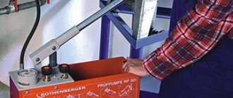
After installing the entire system, it is necessary to carry out hydraulic testing - pressure testing, in which water is supplied to the main line under high pressure (usually its value is 1.5 - 2 times higher than the working one).
Rice. 18 PEX and PE-RT pipes
Recommendations for choosing wisely
The main difficulty lies not only in the installation of the collector itself, but also in the correct choice of equipment.
When choosing a comb model, you should focus on the following parameters:
All operational parameters are indicated in the product passport.
To install floor-by-floor independent heating circuits equipped with autonomous control, combs must be installed on each floor of the house.
When selecting and installing floor distributors, they are guided by the parameters of the “subsystem” that they are intended to serve.
Thanks to the floor-by-floor arrangement of the combs, if necessary, you can always turn off the heating of both several individual devices and the entire floor
This greatly simplifies the maintenance and repair of the heating system.
Since a collector block is not a cheap pleasure, in order to protect yourself from disappointment when the system quickly fails, when choosing a model, you should focus on products from trusted manufacturers.
You can safely trust such manufacturers as GREENoneTEC , Rehau , Soletrol , Oventrop and Meibes . In each series of leading European manufacturers you can select a complete set of necessary additional equipment.
Auxiliary elements and fittings for the collector block must also comply with GOST and TU.
As additional devices for connecting the manifold, you may need: 1 - automatic air vent, 2 - adapter, 3 - angle, 4 - tap, 5 - outlet, 6 - another angle, 7 - pipe outlets
Each of the additional structural elements performs its own function:
If you plan to connect a water heated floor from the collector, you will additionally need to install a tap for refilling.
To fix the collector to the wall, you will also need clamps mounted on plastic dowels. When installing the structure, it is also permissible to use special brackets.
Such designs are convenient in that the upper manifold in them is pushed forward, so that the pipes of the unit do not interfere with the pipeline supply to the lower manifold.
Pipe selection
Although pipelines made of various materials can be used to supply water and install circuits, in everyday life they mainly use polymers, which are supplied in coils of various lengths and are easily bent when laying loops.
The main materials of heating pipelines are: metal-plastic made of cross-linked polyethylene PEX with an aluminum layer between the inner and outer shells, cross-linked PEX and heat-resistant PE-RT polyethylene.
It should be noted that metal plastic is not very practical as a material for heated floors - due to its high rigidity, it is difficult to bend with a small radius, and mechanical impact on the surface during installation or before laying the screed leads to bends and breaks. You can repair a metal-plastic pipeline by inserting a section connected using compression or crimp fittings - this leads to a decrease in the passage channel and an increase in hydraulic resistance.
Pipes made of cross-linked and heat-resistant polyethylene have the same service life of about 50 years; it is believed that the PE-RT pipeline is easier to install in rooms with low temperatures, and if damaged, it can be easily repaired by soldering, although the technology is not very well known. Also, the cost of PE-RT is lower than cross-linked polyethylene PEX, although there are enough products of both categories at a relatively low price on the construction market.
Rice. 19 Basic pipe laying schemes for heated floors
How does the collector work?
Water floors are laid in various ways, for example, concrete or flooring, but regardless of the technology chosen, it is necessary to purchase and install a manifold cabinet.
On a note
It is recommended to install the collector box on the wall as close to the middle as possible and most often near the floor.
In the future, two pipes will be inserted into it:
- supply, which leaves the boiler and supplies hot coolant to the system;
- return, which performs an absolutely opposite role: it serves to collect water that has already been used and has had time to cool. It is returned back to the boiler, and the process is repeated again.
The cyclical nature of the process is ensured by another built-in component of the system - a circulation pump. One way or another, during the operation of a heated floor, say during repair work, the system has to be turned off. To do this, each of the pipes is equipped with shut-off valves. A plastic pipe and a metal shut-off valve are connected to each other through a compression fitting. Then a comb is connected to the valve, mounting an air vent on one end and a drain valve on the other. After assembling the cabinet, they proceed directly to installation. And only with a comb already installed on the wall can you cut the circuit pipes to length.
On a note
To ensure the tightness of the connection, the pipes are cut strictly at a right angle.
Pipeline laying options
The main pipe laying schemes during installation are zigzag and spiral volute, the latter provides more uniform heating and is considered the best in efficiency. When laying pipes, a certain distance between sections must be maintained; it depends on the layout and thickness of the screed; its typical value for the usual thickness of the cement-sand layer is in the range of 150 - 200 mm.
The distribution manifold is the main unit in an individual heating system containing two or more underfloor heating circuits; it performs the functions of distributing and mixing the coolant to reduce its temperature. During installation, a pipeline made of cross-linked or heat-resistant polyethylene is placed under a screed in the form of a zigzag or snail and connected to the combs using Eurocones, which ensure a quick and tight connection.