SHARE ON SOCIAL NETWORKS
FacebookTwitterOkGoogle+PinterestVk
The most important conditions for ensuring the proper functioning and efficient operation of the heating system are its proper installation and distribution. Today, many schemes are available that allow you to implement any heating project in accordance with the specifics and layout of the house. The maximum efficient output of the circuits can be provided by heating collectors, which are the subject of this article.
Using the distribution manifold, you can regulate the temperature, pressure and volume of the coolant
Pipe selection
The main point of installing collector wiring is the correct choice of pipes. In the installation of this system, a large number of connections are used, which entails the use of a large number of clamps and fittings. For this purpose, soft, flexible suture metal-plastic or polyethylene pipes are most suitable. Copper pipes are used to exit the pipes from the manifold.
These pipes have the properties of preventing air from entering due to a special coating on the outer surface.
The most optimal pipe diameter is 16 mm. However, you should consult a specialist on this issue.
Selecting pipes for a heating system for a residential building or apartment
When creating a manifold wiring diagram for heating a low-rise residential building or other private building, it is necessary to take into account the method of laying pipes throughout the house. If the piping will run under the floor, in a concrete screed, then it is recommended to buy heating pipes in coils so as not to make connections in the floor, as mentioned above.
Plastic pipes must have sufficient flexibility, the pipe material must not be subject to corrosion and the influence of aggressive environments, must not be destroyed at low or too high temperatures, and the service life of the pipes must be extremely high.
The requirements for temperature resistance and tensile strength of pipes are determined by the performance characteristics of the installed heating system in a house or apartment. For individual development, the pressure in the pipes should not exceed 1.5 atm, and the maximum temperature regime should be in the range of 50C -75C. If the house has a “warm floor” system, then the temperature of the coolant in the pipes should not rise above 30C -40C.
Manifold for combined heating
When installing a manifold circuit, the pressure in the pipes will always be high, and the pipe material must withstand ≥ 10-15 atm. at a coolant temperature of up to 110-120C. Therefore, when laying heating pipes in an apartment building, it is recommended to use corrugated pipes made of stainless steel, rather than metal-plastic or PVC products. As a working example, we can cite the Kofulso brand of pipes, which can withstand pressures of more than 15 atm. at coolant temperature ≥ 110C. The pressure force that causes the destruction of this material is 215 kgf/cm², which is an excellent indicator.
Collector wiring in the apartment
The bending radius of such stainless pipes is equal to their diameter, which allows them to be laid in almost any place and with any bend, without fear that the pipe will leak at the bend. Connections in such piping are made using special fittings, and the twist points are fixed with a lock nut, which ensures the tightness of the connection of corrugated pipes with silicone seals.
But stainless steel is not the cheapest material, and when installing manifold pipes in a two- or three-story building, such a project will be quite expensive. Therefore, it makes sense to use, for example, PE-X brands. These pipes, like other PVC products, are sold in coils, the length of one pipe is 200 meters, the material is able to withstand pressure up to 10 kgf/cm² at a coolant temperature in the system up to 95C. A short-term increase in temperature up to 110C is allowed.
Corrugated stainless steel pipes
Water pipes made of cross-linked polyethylene are also connected to each other using special fittings in the form of plastic or metal (bronze, brass, copper) fittings with a locking ring, which fits tightly onto the pipe and seals it tightly. The advantage of such pipes is that cross-linked polyethylene has a mechanical memory, that is, assembly is carried out according to the following scheme: the pipe is stretched with a special extender so that a fitting can be inserted, and after some time (up to a minute) the pipe takes on the original diameter and tightly presses the fitting. Additionally, tightness is ensured by a locking ring.
Selecting a distribution manifold
Using a distribution manifold is convenient and practical and has a number of advantages. To choose the right distribution manifold, you need to know in advance which heating devices will be connected to it; this determines what additional devices you will need and the type of manifold itself.
It is better to choose manufacturers who have proven themselves in the market, study customer reviews of the products, and consult with several sellers on the topic of the same collector.
Whatever your capabilities, you must remember that the price of a high-quality distribution manifold and its components cannot be low.
Specifics of distributor operation
Collector design
The collector is a distribution-type device for a heating system, which promotes uniform heat distribution. The cooled water flows back into the boiler under the influence of circulation. The main branches attached to the distributor function independently.
Device design
The intermediate node consists of two parts. The supply comb supplies the coolant to the communications, and the return comb leads it to the heat generator when it cools. Two combs are a collector group, and each of them can connect one circuit or several connections to heating devices. The pressure inside each circuit is adjustable.
Features of work
The principle of operation of collector heating is to heat the water with a heat generator and send it to the supply comb. Due to the large internal diameter of the unit, the liquid contained in it slows down the speed and is distributed over all outlets.
The coolant moves to the individual circuit through connecting pipes with a smaller diameter than the distributor. Heated water can be directed to radiators and underfloor heating systems, ensuring uniform heating of each element.
After entering the circuit and releasing heat, the water moves through another pipeline to the distributor. The direction will be the opposite. Having reached the return comb, the coolant is sent to the heat generator.
Operating principle of the collector system
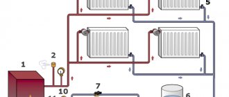
The collector system operates on the following principle: the coolant heated by the boiler, using a circulation electric pump installed between the supply and return lines, enters the collector distribution comb, to the output fittings of which the heating circuits are connected. The overall temperature of the coolant in all circuits is set by a thermostat located on the inlet fitting of the supply comb, and each outlet to the loop is equipped with a flow meter, with the help of which the volume of coolant flowing through the circuit is manually set.
After passing through the circuits, the cooled coolant enters the return line and is pushed by an electric pump to the boiler, in which it is heated. Circulating in a circle, the heated liquid is returned to the supply manifold, which distributes it over individual heating circuits.
In most designs, return line distribution units are equipped with shut-off valves - this allows the installation of electric servo drives on them to automatically regulate the flow passing through the circuits.
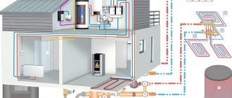
Rice. 2 The principle of collector heating
Types of collectors
Manifold for radiator heating
The collector is designed for a closed circulation heating system. The device comes in several modifications.
Radiator manifolds
The water device is placed on the battery and promotes uniform distribution of water in each section. It can be connected at the top, side, bottom or inserted diagonally. If you have an apartment, a bottom installation would be optimal - the contours are hidden under the baseboard or floor covering.
A private house is equipped with radiator distributors on each floor. They are placed in the center of the wiring, hidden in niches or special cabinets. If the same number of rings is not supplied to the collector devices, an individual circulation pump is used for each outlet.
The radiator type of mechanisms has several connection features:
- branches of the distribution unit form separate circuits with shut-off valves;
- for heated floors, copper or polypropylene pipes are used;
- the connection is made using one-piece fittings;
- valves are installed to regulate the amount of coolant;
- the circulation sediment is located in the intermediate unit at the entrance to the return pipe;
- the number of pipes depends on the number of rooms connected to one comb.
Thermohydraulic distributor
Hydroarrow
The hydraulic arrow is used in a productive or branched heat supply system, to which multi-storey buildings are connected. On one side of the link-link there is a circuit for a heating boiler, on the second - heating radiators or heated floors.
The distribution hydraulic manifold provides:
- elimination of sudden changes in water temperature;
- increasing operational resources in the system;
- saving fuel and electricity;
- maintaining a constant volume of water in the reservoir through mixing and secondary circulation;
- compensation of secondary circuit coolant costs;
- separation of the boiler hydraulic circuit from the secondary wiring;
- maintaining the temperature balance of heating communications.
Solar collector devices
Solar collector diagram
In regions without autonomous water supply or non-gasified areas, heating can be realized using solar collectors. Structurally, the devices are designed like greenhouses capable of accumulating solar energy. The coolant circulates naturally - circulation flows are created by fans of the absorber plate.
The sun's rays are received by a distributor in the form of a flat box. The black heat-receiving plate accumulates heat flows and transfers them to the heat carrier, which uses air flow or water. Innovative systems work in the direction of the sun's movement.
Solar installations are expensive, and even in the southern regions they are used as an auxiliary heating device.
Installation nuances
The technology for attaching the collector to the wall is quite simple: the TC and radial distribution comb are suspended on mounting brackets, the loops are connected with Eurocone fittings. Pipes going to the top of the collector (usually the “return”) are passed under the bottom.
Advice. No one is forcing you to mount the distributor on brackets. If necessary, the tubes can be spread apart and mounted separately on the wall. The collector box is used in residential areas; when installing the collector in the boiler room, the cabinet is not needed.
Let's briefly list the main points:
- The size of the comb is selected according to the diameter of the pipes used in the heating loops - Ø16 or Ø20 mm. Accordingly, we take a ¾ or 1 inch distributor. The material of the product does not matter; in terms of price/quality ratio, stainless steel wins.
- If the number of comb outlets exceeds 12, assemble a collector assembly of 2 sections. When installing accessories, winding materials are not used, since the parts are equipped with rubber seals.
- A heavier common house collector is suspended on hooks, reinforced brackets, or installed on the floor. Pumps, pipes and other piping elements must not load the distributor with their own weight.
- The hottest coolant receives an indirect heating boiler. The coil and circulation pump of the water heater are connected to the comb directly, usually from the end.
- The radiator heating and TP branches are connected to the manifold through mixing units with three-way valves. A separate pump is installed on each line, selected for pressure and performance.
A heavy coplanar comb can be installed on the floor - weld metal supports
Important point. The mixing unit for heated floors can be installed in the boiler room, near the main comb. Then water at the required temperature will flow to the TP distributor.
Disadvantages and advantages of the collector circuit
The complexity of piping when implementing a collector circuit is compensated by its advantages:
Each radiator is an autonomous and separately controlled element
That is, in each room you can set the desired temperature regardless of the temperature in the boiler or in other heating circuits, or turn off the radiator (group of radiators) without stopping the heating system; Taking into account the fact that each heat pipe connected to the manifold from the heating system transports hot liquid to only one heating device, it is more advisable to use pipes of reduced diameter compared to the calculated total diameter of the pipes. In this case, it is recommended to maintain the minimum permissible distance between the heating device or group of radiators and the collector.
Separate connection of heating devices
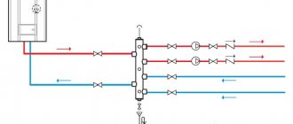
A homemade or factory-made collector heating system, the diagram of which for general cases is given above, is valued by consumers due to the possibility of creating several independent heating circuits with different temperatures and pressures. This scheme allows you to organize different temperature conditions for different rooms in the same building with one boiler. To connect several circuits, another version of the collector is equipped - a hydraulic arrow, which outwardly looks like a large water pipe.
The hydraulic arrow is installed differently from the manifold - the circulation cycle is closed between the coolant supply pipe and the return pipe. The boiler continues to continuously heat the liquid in the primary circuit, and the coolant in the hydraulic arrow begins to move, allowing it to be cut into to connect radiators at different points and at different levels.
Due to this unusual connection of radiators to the hydraulic arrow, at the end point of a single heat sink (radiator) there will be different temperature and pressure indicators. Turning on the hydraulic arrow is advisable when combining the distribution of heating pipes using radiators and a “warm floor” system. Homemade hydraulic arrow
At the places where the circuits are connected, the pressure and temperature in the pipes will be different, but if the collector and the drawings of which were developed for circulation pumps will use them, then this difference in drops does not matter. Also, heating circuits can be connected in series (no more than two in a circuit), but with this arrangement of connecting the circuits it will be impossible to regulate separately from each other.
Series connection of collectors
The disadvantages of the collector organization of piping should be noted as follows:
- The energy consumption of the collector circuit is higher than when batteries are connected in series. Moreover, the larger the heated area, the higher the heat costs;
- Manifold heating equipment is designed to operate only in a one- or two-pipe heating system design, which can be routed along the walls of the premises. But when organizing radial distribution, it will not be possible to lay pipes along the walls or in a hidden way due to the large volume of the practical circuit and the large number of heating pipes;
- When laying pipes in the floor under a concrete screed, the following disadvantages of the method appear: for pipes laid under the floor, it is not allowed to make any connections - neither welded, nor threaded, nor any other, in order to prevent hidden leakage, otherwise the layer will have to be removed concrete screed, and this is almost a major renovation of the premises with all the ensuing consequences;
- The total hydraulic resistance of the collector heating circuit will be significant, especially when laying pipes with a small diameter. Also, when implementing a collector pipe routing scheme, it is necessary to use a circulation pump (pumps), since the natural pressure in the pipes will not allow the coolant to move freely through the pipes;
- When using several autonomous heating circuits in a collector heating circuit, each large circuit must have its own circulation pump installed. This leads to financial costs both during installation of the system and during its operation;
- The energy dependence of the collector heating system is one of its significant disadvantages, since circulation pumps require connection to the electrical network. In the event of an emergency power outage, the heating will not be able to provide the required thermal conditions, since the movement of the coolant through the pipeline will simply stop.
Installation and connection rules
It is best to select and install a collector at the stage of design and installation of the heating system.
Such intermediate structures are installed in rooms protected from excess humidity. Most often, space is allocated for these purposes in the hallway, pantry or dressing room.
It is advisable to place the collector block in a metal cabinet specially designed for this purpose, equipped with holes in the side walls for pipe outlets
On sale there are overhead and built-in models of metal cabinets. Each model is equipped with a door and stampings on the sides.
In the absence of the opportunity to install a metal cabinet, it is easier to do it by fixing the device directly to the wall. The niche for arranging the collector block is placed at a low height relative to the floor.
There are essentially no generally accepted instructions for installing collector distribution circuits. But there are a number of main points regarding which experts have come to a common denominator:
- Availability of expansion tank . The volume of the structural element must be at least 10% of the total amount of water in the system.
- The presence of a circulation pump for each laid circuit . Regarding this element, not all experts are unanimous in their opinion. But still, if you plan to use several independent circuits, it is worth installing a separate unit for each of them.
An expansion tank is placed in front of the circulation pump on the return line. Thanks to this, it becomes less vulnerable to the turbulence of water flows that often occur in this place.
If a hydraulic arrow is used, the tank is mounted in front of the main pump, the main task of which is to ensure circulation in the small circuit.
The location of the circulation pump is not important. But, as practice shows, the service life of the device is somewhat higher on the “return” route.
The main thing during installation is to position the shaft strictly horizontally. If this condition is not met, the very first bubble of accumulated air will leave the unit without cooling and lubrication.
The process of assembling and connecting the collector system is clearly presented in the video block.
Mixing unit equipment
Listed above are the main components that you will need to assemble the mixing unit yourself. We will describe the completeness in more detail in the table below.
In addition to the above, other parts of pipeline installation can be used to assemble the mixing unit, such as couplings, American ones, and others. They need to be determined at the location where the mixer is installed. Materials need to be used to seal joints.
As a result of the work on assembling mixers, a control panel for the heating system, called a manifold, is obtained.
Heating system manifold for a private house
It can be quite complex or completely simple, located in the basement or in living quarters in specially made manifold cabinets. The main thing is accessibility for maintenance and repair.
Video: how to assemble a mixing unit with your own hands
Knowing from this article how the parts and devices of the mixing unit interact, the developer, even with minimal plumbing skills, will cope with the assembly task. Carefully install one circuit, the rest will roll like clockwork. I wish you success!
How I installed the collector wiring with my own hands.
1.
I decided to install a gas floor-standing boiler in the basement of my house.
The boiler was installed on a concrete screed five centimeters thick.
2.
For the installation of the main pipelines I used a metal pipe with a diameter of 32 mm.
3.
A closed expansion tank was installed on the supply pipe.
4.
A circulation pump was installed on the return pipe.
Installing taps on both sides of the pump will allow you to change the device without draining the coolant.
Creating forced circulation in the heating system is mandatory. Forced circulation improves the efficiency of heating the coolant, and also simplifies the system and makes it more compact.
5.
We install collectors (distribution “combs”) on the main pipelines.
The combs are positioned so that the lengths to each heating device on the floor are approximately equal.
For example, if the distance from the collector to one radiator is 10 times greater than to the other, then the coolant pressure drop on the extended segment will be much higher than on the short one. The system is doomed to imbalance.
However, a difference of 2 times is not considered unacceptable.
6.
Each collector outlet has its own shut-off valve - a ball valve.
This allows, if necessary, to disconnect any radiator from the entire system without in any way affecting the operation of other heating devices. Each circuit is essentially an independent heating system.
It’s very convenient – I couldn’t be more pleased!
7.
I secured both collectors to a vertically placed metal corner.
8.
The wiring to the rooms was mounted along the basement ceiling using a metal pipe with a diameter of 15 mm.
9.
The rays of the circuits were connected to the collectors with a metal-plastic pipe.
10.
I installed a tap on the return pipe, through which I recharge the entire system.
11.
I punched holes in the floor slabs through which the pipes are connected directly to the heating devices.
12.
He connected the heating radiators to the risers of the circuits with a metal-plastic pipe.
This is my second winter using heating with manifold wiring. The system did not cause any serious failures, but we had to “fight” the formation of air in the system. There will be a separate article about this.
Definitions
A collector (comb) is a type of plumbing fixture that distributes coolant along the contours of consumers. Simply put, this is a piece of thick pipe that has one inlet and several outlets. Its appearance was facilitated by the complication of heating systems, the spread of flooring and radiant radiator wiring, and the increase in the number of heat consumption points in the house.
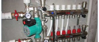
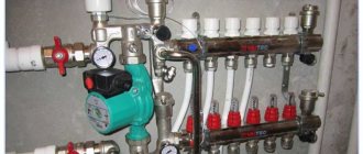
Heating manifold. Click on photo to enlarge.
The coolant flows through the main line from the boiler room to the floor collectors. They have a number of inputs/outputs that corresponds to the number of thermal energy consumers (radiators, convectors, etc.) on the floor. Unlike a series connection (using tees), the collector heating system is distinguished by independent supply to each heating device. This scheme makes it possible to control the temperature regime of each radiator, if necessary, allowing it to be turned off without damage to other heating devices. To do this, each collector outlet is equipped with its own shut-off valves.
Mixed wiring is possible, when several small circuits with independent control are connected to the collector. In this case, a sequential system for connecting heating devices is used within each circuit. With a collector, the heating circuit becomes simpler, allowing you to eliminate the need for seals and additional shut-off and control valves. Using collectors and collector units, you can significantly reduce costs when designing, installing and commissioning a heating system.
We manufacture a distribution manifold
We calculate the material required for the manufacture of the collector. The easiest way to do this is in Excel spreadsheets. At the same time, in this program you can calculate the cost of materials required for the manufacture of the device. We purchase the necessary starting material and prepare tools for self-production.
preparing tools
The starting materials for the main parts of the collector will be regular or square pipes. We make the necessary markings on them using calipers, a ruler and a core.
We make the necessary markings
Using a gas cutter, we make holes for the pipes.
make holes for pipes
We insert the pipes (pipe sections with threads) into the seats.
Insert the pipes
We fix the pipes by welding. First, rough it out, and then scald it around the entire perimeter.
We fix the pipes by welding
We also weld brackets to the body for wall mounting.
We weld the brackets to the body
We clean the welding areas from scale and rust.
Cleaning the weld areas
We treat the entire structure with a degreasing compound and cover it with paint and varnish.
treated with a degreasing compound, coated with paint and varnish
The paint completely sets in two to three days and we have a self-made distribution manifold at our disposal. Now all that remains is to install it in place and connect all the incoming and outgoing circuits to it.
ready-made homemade distribution manifold
A system with a distribution manifold will work much more efficiently than a simple pile of heating pipes
In order to catch all the nuances of making a distribution manifold yourself and the scope of its application, we recommend that you watch the training video.
Ready-made designs of heating collectors
The construction market offers products from various manufacturers of collector heating equipment, including such popular brands as ProfLine, Valtec, Luxor, Rehay, Shout.
The most commonly used materials in the manufacture of manifolds are stainless steel and chrome-plated brass; much less often in domestic heating, equipment is selected from low-cost polymers (polypropylene), which do not provide for the installation of flow meters and valves for servo drives.
Rice. 16 Auditor CO 4.0
Making a solar collector for alternative heating in your home
Recently, the interest of ordinary people in renewable energy sources has increased. Because of this, many homeowners are looking to buy a solar collector for home heating, which converts the sun's energy to heat water. But the decision to buy a solar collector for heating in a store is not always rational. The cost of the finished device is far from budget, so such a purchase can hit the family budget hard.
To avoid expenses, you can make a solar vacuum collector for heating yourself. Various solar collectors for home heating, reviews of which are positive, have the following design details:
- container for storing heated water;
- heat exchanger;
- device for collecting solar energy;
- insulating layer.
The materials from which the collector can be made are very diverse. There are known technologies for the independent production of solar collectors from polypropylene, ordinary garden hoses, window frames, plastic bottles, old refrigeration units and other available materials. The collector assembly diagram directly depends on the type of material chosen, so it is worth studying after the owner has decided on the concept of the collector.
Self-made vacuum solar collectors for home heating, the price of which in the store is $200 or more, can be used as full-fledged heating sources.
Vacuum solar collectors have a number of advantages:
- energy efficiency;
- environmental friendliness;
- autonomy;
- availability.
It is not difficult to make traditional distribution or solar collectors for heating your home with your own hands. This does not require large material costs, complex technological equipment or solid experience. However, these hand-made devices will greatly optimize the home heating system and will help the owner create a reliable, efficient and uniform source of heating for his home.
- How to fill water into an open and closed heating system?
- Popular floor-standing gas boiler made in Russia
- How to properly bleed air from a heating radiator?
- Expansion tank for closed heating: device and principle of operation
- Gas double-circuit wall-mounted boiler Navien: error codes for malfunctions
Recommended reading
Heating thermostat - operating principle of different types How to make an expansion tank for heating with your own hands? Bypass in a heating system - what is it and why is it necessary? Expansion tank for closed heating: device and principle of operation
2016–2017 — Leading heating portal. All rights reserved and protected by law
Copying site materials is prohibited. Any copyright infringement will result in legal liability. Contacts
Purpose of the heating manifold
The absence of a distribution manifold in a water heating system can lead to the fact that water may flow unevenly into different circuits of the system. As a result, you will have a hot floor and cold radiators, or vice versa.
This may occur because several heating system circuits can be connected to one boiler outlet. The liquid flows unevenly through such connections, as a result of which part of the premises will not have enough heat. But the efficiency of the heat supply system depends on the amount of coolant passing through the pipes, the volume and speed of its movement.
pipes coming from the boiler
Some home owners try to solve this problem by installing additional pumps and control valves. But this only complicates the system and does not always lead to uniform distribution of the coolant.
How is the coolant distributed in a private house?
Let’s take, for example, a heating system for a private house with an area of 100 square meters. The device for heating water will be a wall-mounted gas boiler with one outlet pipe with a diameter of ¾ inches.
In our house we have two heating circuits and one circuit that heats water for domestic use with indirect heating. All circuits are built from pipes with a diameter of 1 inch. How to calculate and build an effective heat supply system?
First of all, we understand that the main reason for poor-quality heat supply is an elementary lack of coolant in the system. But the main reason for this shortage is excessively narrow distribution pipelines.
Thus, you can increase the efficiency of the thermal system, that is, increase the diameter of the distribution pipes in two ways:
heat flow distribution
- When using boilers with built-in pumps, a hydraulic arrow (flow distributor) is connected to them. In this case, each heat consumption circuit must have its own circulation pump. But such a device will only work in a small building. As the heated area increases, its efficiency and reliability drops sharply.
- The most reliable way is to connect a water distribution manifold to the heat source.
The most advanced type of distribution manifold is called camplanar. With its help, the problem of connecting pipes of different diameters and volumes of placed coolant is effectively solved.
distribution hydraulic manifold for 4 circuits
Let's look at how to create heat flow distribution systems with your own hands.
What is it needed for
When installing water pressure systems, there is a rule: the total diameter of all branches should not exceed the diameter of the supply pipe.
In relation to heating equipment, this rule looks like this: if the diameter of the boiler outlet fitting is 1 inch, then the system allows two circuits with a pipe diameter of ½ inch. For a small house heated only with radiators, such a system will work effectively. In fact, there are more heating circuits in a private house or cottage: heated floors. heating of several floors, utility rooms, garage. When they are connected through a tapping system, the pressure in each circuit will be insufficient to effectively heat the radiators, and the temperature in the house will not be comfortable.
Therefore, branched heating systems are made using collector systems; this technique allows you to adjust each circuit separately and set the desired temperature in each room. So, for a garage, plus 10-15ºС is enough, and for a nursery, a temperature of about plus 23-25ºС is required. In addition, heated floors should not heat up more than 35-37 degrees, otherwise it will be unpleasant to walk on them, and the floor covering may become deformed. With the help of a manifold and shut-off temperature, this problem can also be solved.
Video: using a collector system for heating a house.
Manifold groups for heating systems are sold ready-made, and they can have different configurations and the number of outlets. You can select a suitable collector assembly and install it yourself or with the help of specialists.
However, most industrial models are universal and do not always fit the needs of a particular home. Redesigning or modifying them can significantly increase costs. Therefore, in most cases it is easier to assemble it from separate blocks with your own hands, taking into account the characteristics of a particular heating system.
Manifold group for heating system assembly
The design of the universal collector group is shown in the figure. It consists of two blocks for forward and reverse coolant flow, equipped with the required number of outlets. Flow meters are installed on the supply (direct) manifold, and thermal heads are located on the return manifold to regulate the return water temperature in each circuit. With their help, you can set the required coolant flow rate, which will determine the temperature in the heating radiators.
The manifold distribution unit is equipped with a pressure gauge, circulation pump and air valves. The supply and return manifolds are combined into one unit with brackets, which also serve to attach the unit to a wall or cabinet. The price of such a block is from 15 to 20 thousand rubles. and if some of the taps are not used, its installation will be clearly impractical.
The rules for installing the finished block are shown in the video.
Comb - collector unit
The most expensive elements in a manifold distribution block are flow meters and thermal heads. To avoid overpaying for unnecessary elements, you can buy a collector unit, the so-called “comb”, and install the necessary control devices with your own hands only where necessary.
The comb consists of brass tubes with a diameter of 1 or ¾ inches with a certain number of taps with a diameter of ½ inch for heating pipes. They are also connected to each other by a bracket. The outlets on the return manifold are equipped with plugs that allow you to install thermal heads on all or part of the circuits.
Some models may be equipped with taps, with their help you can regulate the flow manually. Such combs have a cast body and are equipped with a fitting/nut thread at the ends, which allows you to quickly and easily assemble a manifold from the required number of branches.
In order to save money, the manifold for heating systems can be assembled from individual elements independently or completely made by hand.
Self-assembly of a collector installation
Polypropylene manifold assembly
You can make a distribution manifold from several materials with your own hands. You will need to select the necessary tools, make calculations, and create a drawing. The calculation takes into account the number of circuits, the presence of heated floors, rooms with maximum and minimum temperatures, and the type of heating on each floor.
The collector connection should have a distance of 10-15 cm, the supply and return combs are 25-30 cm apart from each other. The diameter of the device depends on the type of boiler, but 25.4-38.1 mm will be enough.
Device made of polypropylene
A polypropylene collector mechanism can be made from a 32 mm diameter pipe and 32/32/16 mm tees. A tee is placed on one side of the device, to which an air bleeder is connected at the top, and a drain valve at the bottom. On the other side there is an outlet/supply pipe and a valve. The feed is sent to the boiler.
The 16 mm diameter outlet is equipped with a valve. The entire structure is mounted on the wall with brackets.
Brass knot
A homemade distributor can be made using brass fittings and tees. The lining material will be linen tow or gremetic. After assembly, the device is tested. If the connection is incorrect, it will leak.
Collector made of corrugated pipe
If you have welding skills, you can make a model for a large house with multi-pipe wiring. The system with a hydraulic boom is made from a professional pipe 8x8 or 10x10 cm and a round pipe. Their cross section is calculated based on the thermal power of the system, water speed, and the difference in temperature at the time of supply and return.
The wiring is separated by 15 cm, the collectors by 20 cm. The pipe is placed according to the sketch, and the holes for wiring are made with a gas cutter. Small parts of the tubes are welded to the block in advance. After assembly, mounting brackets are attached to the device by welding.
Finally about homemade collectors
Above in the text we mentioned budget options for combs - tap, polypropylene and homemade. Such distributors can be used without problems in radiator beam circuits. To balance and regulate the flow, a balance valve and a faucet with a thermal head are installed on each battery. The collector is equipped with “air vents” + drain taps.
If you put the indicated combs on the TP, you will encounter the following nuances:
- the distributor cannot be equipped with rotameters;
- without flow meters it is difficult to balance circuits of different lengths;
- Factory plastic manifolds have shut-off valves, which means there is nothing to regulate the flow;
- combs assembled from polypropylene or brass tees have many joints;
- It's worth noting that homemade distributors don't look too good.
A self-made underfloor heating manifold can still be brought to perfection. We assemble the distributor from tees, and on the return connections we mount thermostatic radiator valves with RTL-type thermal heads, as shown in the photo.
A skilled owner can easily make a coplanar common house collector - weld it from a round or profile pipe. But there’s a catch in the calculations: you need to know the cross-section of the chambers and pipes for a specific heating system. If a specialist calculates these parameters, use the experience of the master from the video:
Circulation pump
Both a single-pipe and a two-pipe heating system for a one-story house with forced circulation cannot do without a circulation pump, due to which the coolant moves in the system. When choosing a pump, you must first consider its power.
The required pump power is calculated using the following formula:
- Q = Qn / 1.163 x Dt,
- Where Q is the pump power,
- Qn is the amount of heat required to warm up the house,
- Dt – temperature difference in the supply and return circuits.
The circulation pump must be located on the return pipe in close proximity to the boiler. During installation, it is necessary to install a heating bypass with three taps and a filter that will prevent the pump from clogging with solid particles in the heating system.
On the market you can find suction pumps that are designed to be installed on a supply pipe. The connection diagram for a heating boiler with forced circulation rarely includes such devices - they are too expensive and in the vast majority of situations do not justify their price tag.
Calculation of collector heating
The homeowner does not need to calculate the parameters of the collector (its flow diameter, length, cross-section of the outlet fittings) and the diameter of the pipes when purchasing a standard product. If you want to make such calculations, you can find the necessary formulas on the Internet, although in this case it is easier to focus on the standard dimensional parameters of manufactured factory products.
The main task of the calculations is to determine the length of the pipes to ensure the required temperature in the room with known temperature characteristics of the coolant. To do this, there is no need to resort to complex engineering calculations, which can only be carried out by narrow specialists in the field of heating; for the average person it is easier to use an online calculator or computer program.
To obtain the desired result, initial data about the required temperature in the room and its area, the diameter and pitch of the pipes, and the temperature of the medium are entered into the program or calculator. On the Internet you can find reviews of calculation programs Audytor CO from Sankom, Valtek Complex from the company of the same name, Raucad/Rauwin 7.0 from Rehau.
Rice. 17 Assembling the collector block
Flaws
There are several main disadvantages that must be taken into account before installing such a system in your home:
- Much more pipe is used to connect all the components than a series connection. The larger the area of the house, the more complex the wiring plan. This increases the difference in costs.
- Ordinary one- or two-pipe heating is usually mounted on walls. In this case, such mounting will not be aesthetically pleasing.
- The location of the connections in the screed has one important factor - there should be no seams or joints. After all, this is a potential leak point. And opening up a concrete floor is an unpleasant idea.
- The total resistance of the water circuit is high, especially when heating a two-story house. Especially when installing narrow pipes. You can immediately forget about natural circulation, because a small difference is definitely not enough. The solution is obvious - a powerful pump.
- The use of several circuits at once usually forces the installation of the same number of pressure systems. All this increases the consumables not only at the time of installation, but also during use.
- Connecting forced circulation automatically makes the system dependent on electricity. Any problems with this type of energy can lead to heating failure when the boiler is completely working.
Modifications of distributor combs
Today, there are many types of collectors for heating systems on the equipment market.
Manufacturers offer both connecting links of the simplest design, the design of which does not provide for the presence of auxiliary fittings for regulating the equipment, and manifold blocks with a full set of built-in elements.
A collector block that includes all the necessary functional elements to create conditions for uninterrupted and high-performance operation of the heating system
The simple-to-use devices are brass models with one-inch branches, equipped with two connecting holes on the sides.
On the return collector, such devices have plugs, instead of which, in the case of “expanding” the system, additional devices can always be installed.
Intermediate assemblies that are more complex in design are equipped with ball valves. For each outlet they provide for the installation of shut-off control valves. Sophisticated, expensive models can be equipped with:
- flow meters , the main purpose of which is to regulate the flow of coolant in each loop;
- temperature sensors designed to monitor the temperature of each heating device;
- automatic air release valves
- electronic valves and mixers aimed at maintaining the programmed temperature.
The number of circuits, depending on the connected consumers, can vary from 2 to 10 pieces.
Regardless of the complexity and versatility of the equipment, materials that are resistant to external factors are used in the manufacture of manifold block combs
If we take the manufacturing material as a basis, then intermediate prefabricated collectors are:
- Brass - characterized by high performance parameters at an affordable price.
- Stainless steel structures are extremely durable. They can withstand high pressure with ease.
- Polypropylene - models made of polymer materials, although they have a low price, are inferior in all characteristics to their metal “brothers”.
Models made of metal are treated with anti-corrosion compounds and covered with thermal insulation to extend their service life and improve performance parameters.
Separating structures made of polymers are used in the construction of systems heated by boilers with a power of 13 to 35 kW
Parts of the device can be cast or equipped with collet clamps, allowing connection to metal-plastic pipes.
But experts do not advise choosing combs with collet clamps, since they often “sin” by leaking coolant at the valve connection points. This occurs due to rapid failure of the seal. And it is not always possible to replace it.
Collectors are used in single- and two-pipe heating schemes. In single-pipe systems, one comb supplies the heated coolant and receives the cooled one
Installation of heating with forced circulation in a one-story house
Do-it-yourself heating of a one-story house is done using a technology that includes the following operations:
- First of all, the heating boiler is installed;
- The boiler is connected to a chimney that is led outside the building;
- When using a gas boiler, you must connect to the main line (this operation must be performed by specialists from the gas service);
- Heating batteries are installed along the walls in pre-selected places;
- All structural elements are connected by pipelines;
- The circulation pump and expansion tank cut into the return pipe;
- The pipelines are connected to the corresponding boiler nozzles;
- The assembled system must be launched in test mode, after which it can be put into operation.
This technology is common to all types of heating systems - there are minor differences only in the laying of pipes and installation of radiators.
