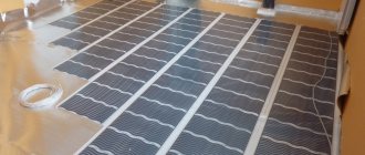
The traditional heating system in the form of radiators was the only source of heat for a long time, but today it is being replaced by heated floors. They are electric and water. The key to efficient operation of water heating is the presence of a collector and its correct installation.
This article will be useful to those who are planning to install heated floors in their home and install the collector themselves. In it we will talk about the existing types of this equipment, their structure and installation method.
Purpose and types
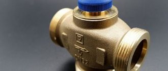
A warm water floor is distinguished by a large number of pipe circuits and a low temperature of the coolant circulating in them. Basically, heating the coolant to 35-40°C is required. The only boilers that can operate in this mode are condensing gas boilers. But they are rarely installed. All other types of boilers produce hotter water at the outlet. However, it cannot be run into the circuit at this temperature - a too hot floor is uncomfortable. To reduce the temperature, mixing units are needed. In them, in certain proportions, hot water from the supply and cooled water from the return pipeline are mixed. After which, through the manifold for the heated floor, it is supplied to the circuits.
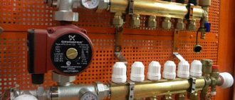
Manifold for underfloor heating with mixing unit and circulation pump
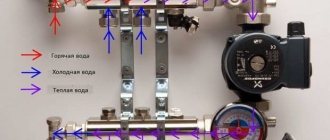
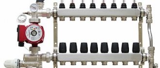
To ensure that all circuits receive water at the same temperature, it is supplied to a heated floor comb - a device with one input and a number of outputs. Such a comb collects cooled water from the circuits, from where it enters the boiler inlet (and partially goes to the mixing unit). This device - supply and return combs - is also called a manifold for heated floors. It can come with a mixing unit, or maybe just combs without any additional “load”.
Materials
The manifold for heated floors is made of three materials:
- Of stainless steel. The most durable and expensive.
- Brass. Average price category. When using high-quality alloy, they last a very long time.
- Polypropylene. The cheapest. For working with low temperatures (as in this case), polypropylene is a good budget solution.
Manifold for underfloor heating with 6 circuits
During installation, the inputs of the heated floor circuits are connected to the supply comb of the manifold, and the loop outputs are connected to the return comb. They are connected in pairs to make adjustments easier.
Equipment
When installing a water heated floor, it is recommended to make all contours the same length. This is necessary so that the heat transfer from each loop is the same. It’s just a shame that this ideal option doesn’t come around very often. Much more often there are differences in length, and significant ones.
To equalize the heat transfer of all circuits, flow meters are installed on the supply comb, and control valves are installed on the return comb. Flow meters are devices with a transparent plastic cover with printed graduations. There is a float in the plastic case, which marks the speed at which the coolant moves in a given loop.
It is clear that the less coolant passes through, the cooler the room will be. To adjust the temperature regime, the flow rate on each circuit is changed. With this configuration of the manifold for heated floors, this is done manually using control valves installed on the return comb.
The flow rate is changed by turning the knob of the corresponding regulator (they are white in the photo above). To make it easier to navigate, when installing the collector unit, it is advisable to sign all the circuits.
Flow meters (right) and servos/servos (left)
This option is not bad, but you have to regulate the flow rate, and therefore the temperature, manually. This is not always convenient. To automate the adjustment, servo drives are installed at the inputs. They work in tandem with room thermostats. Depending on the situation, a command is sent to the servo drive to close or open the flow. In this way, maintaining the set temperature is automated.
Filling with water and pressure testing for leaks
Once connected, it’s time to fill the system with water.
This should be done not through the heating boiler, but directly through the drain and fill taps. They are located on the rear plug of the distribution manifold.
Mistake #4 - if you pump water through the boiler, there is a risk of failure of the circulation pump.
In this case, be sure to shut off the ball valves with the supply from the boiler.
Next, using a special key, close all circuits except one. This is where you will begin filling the system with water.
Also close all valves on the rotameters, except one.
Now you can connect the water hose to the drain valve on the supply comb.
A hose for draining water is connected to the return comb. After which you can slowly let the water in.
Lower the drain hose from the return comb into the sewer or simply into a bucket and wait until all the air has drained.
As soon as one water flows, the valve of this circuit can be closed and proceed to the next one. The whole procedure is repeated again.
After filling all the circuits, you can begin supplying water to the distribution system through the heating unit or the boiler itself.
Only after this do you open the ball valves on the manifold and finally release the remaining air through the air vents.
Before pouring the screed, the underfloor heating pipelines themselves should be checked for leaks.
Tests are carried out in cold water. In this case, the test pressure must exceed the working pressure by 1.5 times.
As a rule, hydraulic tests take place within 3 hours. During the first hour, every 10 minutes the decreasing pressure is adjusted to the required level.
And over the next 2 hours, a control measurement is taken.
The pressure in a working and serviceable system should not drop from the original by more than 2 bar.
Mistake #5 - trust only pressure readings, without visually and physically (by hand) checking the joints.
You definitely need to make sure that not only the tubes are tight, but also all joints and connections. The fact is that a slight undermining is not determined by a drop in pressure.
As a result, satisfied with all the readings, you will finally fill the screed and install the entire system. And after a while, these wet places will show themselves in all their glory.
As an exception, if your site has a negative temperature, pneumatic tests with compressed air or inert gas are allowed for floor-mounted systems.
The tightness of each connection is checked with a foaming compound.
Hydraulic tests are usually documented in a protocol.
Typical connection diagrams
Water heated floors are rarely used as the only source of heating. Heating only due to underfloor heating is permissible only in regions with a mild climate, or in rooms with a large area, where heat removal is not limited by furniture, interior items or the low thermal conductivity of the floor covering. Almost always it is necessary to combine radiator circuits, hot water preparation devices and underfloor heating loops in one heating system.
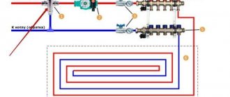
Typical diagram of a combined heating system with connection of radiators and underfloor heating circuits. This is the most technologically advanced and easily customizable option, but it also requires significant initial investment. 1 - heating boiler; 2 — safety group, circulation pump, expansion tank; 3 - manifold for separate two-pipe connection of radiators in a star configuration; 4 — heating radiators; 5 - underfloor heating manifold, includes: bypass, three-way valve, thermostatic head, circulation pump, combs for connecting underfloor heating circuits with gearboxes and flow meters; 6 - heated floor contours
There are quite a large number of variations in the design of the boiler room piping, and each individual case has its own principles of operation of the hydraulic system. However, if you do not take into account very specific options, then there are only five ways to coordinate the operation of heating devices of various types:
- Parallel connection of the underfloor heating collector to the main line of the heating unit. The insertion point into the main line must be made up to the connection point of the radiator network; the coolant supply is provided by an additional circulation pump.
- Association according to the type of primary and secondary rings. The line, wrapped in a ring, has several supply connections in the supply part; the coolant flow in the connected circuits decreases with distance from the heating source. Flow balancing is performed by selecting the pump supply and limiting the flow with regulators.
- Connection to the extreme point of a coplanar manifold. The movement of the coolant in the heated floor loops is ensured by a common pump located in the generator part, while the system is balanced according to the principle of priority flow.
- Connection through a hydraulic separator is optimal when there are a large number of heating devices, a significant difference in flow rates in the circuits and a significant length of underfloor heating loops. This option also uses a coplanar manifold, but the hydraulic arrow is necessary to eliminate the pressure drop that interferes with the correct operation of the circulation pumps.
- Local parallel loop connection via unibox. This option is well suited for connecting a short-length heated floor loop, for example, if you need to heat the floor only in the bathroom.
The simplest option is to connect a heated floor circuit to a radiator heating system with a coolant temperature of 70-80 °C. 1 - line with supply and return of the high-temperature circuit; 2 - heated floor contour; 3 - unibox.
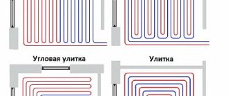
It must be remembered that the nature of the operation of a heated floor may also change depending on the installation pattern of the coil. The “snail” scheme is considered optimal, in which the tubes are laid in pairs, which means that the entire area is heated almost evenly. If the warm floor is arranged as a “snake” or “labyrinth”, then the formation of colder and warmer zones is practically guaranteed. This drawback can be eliminated, including through proper configuration.
Installation of a system with flow meters
The flow meter is installed on the return of the collector, as recommended by the manufacturers.
However, a feed installation option is possible. The main and important requirement for installing the device is to place it strictly vertically . This facilitates the correct calculation of the coolant level. The collector is placed in a horizontal position.
Automatic operation of the collector and rotameter requires the connection of a temperature sensor. This allows you to block the access of water to the loops when the desired heating degree is reached.
Flow meter installation:
- The device is screwed into the collector socket with a key in a strictly vertical position. The rotameter has an O-ring and a nut.
- Twist and remove the flask by turning it counterclockwise. Remove the ring and return the flask to its original position.
- Turn the brass ring clockwise, bringing it to the desired value, to find the balance of the speed of incoming water.
- Place a cover over the ring to protect it from damage.
At the end of the process, the system is checked for functionality.
Control elements
Setting up a heated floor collector is impossible without special devices. With their help, the optimal heating mode of the system is established and water flows in the pipelines are regulated. Each of them performs a specific function.
- Water temperature sensor
Installed on the inlet and outlet pipes of the device. These devices do not affect the operation of the system, but indicate the current heating rate. The difference in values can be useful in calculating operating efficiency. They also serve as an indicator of heating mode violations.
- Central thermostat with servo mechanism and sensor.
It is mounted on the inlet pipe of the inlet manifold and connected to the return pipe with cooled coolant. The temperature sensor is placed in the comb body. There is a rotary knob on the body of the thermostat with which you can set the required temperature level. The device receives readings from the sensor about the degree of water heating. Depending on this, the flow of cold and hot coolant is regulated.
- Servo drives on the inlet comb nozzles
According to the principle of operation, they are completely similar to a thermostat, but with minor additions. With their help, the volume of water flow for each circuit of the water floor is regulated. Depending on the model, this can be done in manual or automatic modes. For the latter, servos with built-in temperature sensors are used, which can be connected to a common remote thermostat.
- Flow meters
Devices that are optional for installation, but which, however, can become effective elements for manually controlling the operation of a water heated floor. They are installed on the return manifold pipes and are locking mechanisms with a glass bulb.
When you turn the head on the body, the rod in the device changes its position. This affects the volume of liquid passing through it. For clarity, a measurement scale is printed on the surface of the flowmeter, indicating the flow rate of water l/min.
Homemade designs
The collector has a significant drawback - high cost.
Therefore, many “homemade” people assemble various options for collectors with their own hands, depending on their wallet and the availability of components.
There are two options for this path:
The 3-loop collector circuit can be implemented as follows:
First, you should assemble the collector pipes - return and coolant supplying the heating circuits. To do this, use one comb for 3 channels or 3 single-loop units for each manifold. The return manifold is equipped with a flow sensor or flow meter and a counter-mounted connection unit for return supply hoses along each loop.
Single-loop manifolds are connected by threaded elements into a comb. Each coolant loop contains a heat sensor with an actuator and a connection point for the power line of the thermal circuit. Air vents are connected to one end of the collectors, and at the other, a coolant pump is connected to the collector pipes, and in addition a thermostatic valve or servo drive is connected to this point, which from time to time replenishes the mixer with hot water. The collector assembly is attached to the wall, checked for functionality and connected to the thermal circuits. After this, final installation and configuration of the entire system is carried out.
Here is the simplest working version of a manifold for heated floors, available to a wide range of DIYers. The capabilities of real collectors are often expanded by connecting more complex control and metering systems.
For example, they connect heat meters, additional temperature meters and much more, no matter what - that’s why homemade inventors exist, to “assemble something yourself.”
If a homemade manifold is soldered from polypropylene pipes, then you need to replenish your arsenal of tools with a special soldering iron for welding parts made of this polymer.
When assembled by welding, the size of each single-loop unit increases due to the seams, and if there are more than 3 thermal circuits, then the entire collector becomes bulky and its installation becomes problematic. Otherwise, the design of the plastic manifold and its settings are no different from those described earlier.
Well, now it's time to finish the article. All the material I wanted to share has been reviewed. I hope it will be useful to you, and you will use it if you need to install a manifold for a heated floor with your own hands. Improve your own practical skills and gain new knowledge, as they say: “It’s never too late to learn!” That's all, thank you for your attention, successful and easy repair!
How does the collector work?
Water floors are laid in various ways, for example, concrete or flooring, but regardless of the technology chosen, it is necessary to purchase and install a manifold cabinet.
In the future, two pipes will be inserted into it:
The cyclical nature of the process is ensured by another built-in component of the system - a circulation pump. One way or another, during the operation of a heated floor, say during repair work, the system has to be turned off. To do this, each of the pipes is equipped with shut-off valves. A plastic pipe and a metal shut-off valve are connected to each other through a compression fitting. Then a comb is connected to the valve, mounting an air vent on one end and a drain valve on the other. After assembling the cabinet, they proceed directly to installation. And only with a comb already installed on the wall can you cut the circuit pipes to length.
Manufacturing materials
The reliability and durability of the collector directly depends on the material from which it is made. A comb for heated floors can be metal or polymer. Each option has its own advantages and disadvantages.
Polypropylene
A manifold made of polypropylene pipe is an extremely economical option. In addition to the affordable price, one can note the light weight of the device. Models with fittings and combs with shut-off ball valves are available for sale. To connect metal products, combined fittings are used.
The disadvantages of polypropylene collectors include:
- thick walls, due to which the passage cross-section is smaller than that of metal combs of the same size;
- less strength and durability compared to metal models;
- oxygen permeability - even if polypropylene is reinforced with fiberglass reinforcement, there is diffusion of oxygen, which provokes corrosion of steel elements of the heating system and boiler.
Collector block made of polypropylene Source chudopol.ru
How to save money on a mixing unit
Many master plumbers consider it an integral part of the underfloor heating manifold, although these are 2 different elements that perform separate functions. The task of the comb is to distribute the coolant along the circuits, and the mixing unit is to limit its temperature to 35-45 °C, maximum 55 °C. The collector connection diagram shown below works according to the following algorithm:
- While the system is warming up, the two-way valve on the supply side is completely open and allows maximum water through.
- When the temperature rises to the calculated value (usually 45 °C), the remote sensor acts on the thermal head, and it begins to block the flow through the valve, pressing on the rod.
- After the valve mechanism is completely closed, the coolant, stimulated to move by the pump, circulates only in a closed floor heating network.
- The gradual cooling of the water is detected by a temperature sensor, causing the thermal head to release the rod, the valve opens and a portion of hot water enters the system, while some of the cold water goes back. The heating cycle repeats.
Good news for those who are very limited in funds, but want to heat themselves with warm floors: installing a two- or three-way valve with a pump is not always necessary. There are two ways to reduce the cost of the system by avoiding the purchase of a mixer:
- power the heating circuits directly from the gas boiler through the manifold;
- install RTL thermal heads on the manifold valves.
The manifold assembly, assembled from brass tees, provides for regulation by automatically limiting the reverse flow with RTL heads.
Let us immediately note that the first option contradicts all the canons and cannot be considered correct, although it is used quite successfully. The bottom line is this: high-tech wall-mounted gas boilers can maintain the temperature of the supplied water at 40-50 °C, which is acceptable for heated floors. But there are 3 negative points:
- In spring and autumn, when there is minimal frost outside, the boiler will not be able to lower the coolant temperature below 35 ° C, causing the rooms to become stuffy and hot due to heating of the entire floor surface.
- In the minimum combustion mode, the parts of the heating unit are covered with soot twice as quickly.
- Due to the same mode, the efficiency of the heat generator is reduced by 5-10%.
Thermostatic heads of the RTL type operate on the principle of a two-way valve, only they are located on each circuit and are not equipped with remote sensors. A thermoelement that responds to changes in water temperature is located inside the head and blocks the flow along the circuit when it has heated up above 45-55 ° C (depending on the adjustment). In this case, the comb is connected directly to a heat source running on any type of fuel - wood, diesel or pellets.
Important condition. For normal operation of heated floors controlled by RTL thermal heads, the length of each circuit should not exceed 60 m
More details about the design of such heating and the correct schemes for assembling the collector are described in a separate instruction and in the next video:
Distributor made of metal fittings
If you use metal fittings instead of polypropylene, you will be able to slightly reduce the size of the structure and do without a soldering iron. But here another pitfall awaits you in the form of cheap thin-walled tees, which are scary to handle with a pipe wrench - low-quality material can crack. If you buy high-quality fittings, then the total price of the product will be closer to the factory manifold, although the savings will still remain.
For manufacturing, you need to select internal/external thread tees made of good brass, shown in the photo, and ball valves with a low stem and a butterfly handle. The same radiator valves will go to the second part of the comb. The assembly technology is simple: pack the threads with flax or thread and twist the fittings together, and then install the taps and other parts.
Advice. When assembling, try to direct all the side bends in one direction, as well as the valve stems, so that the homemade manifold looks presentable. When screwing on pipeline fittings, remove the handles and adjusting caps so that they do not cling to adjacent taps.
Installing flow meters on a comb of brass fittings is a difficult issue. Then the supply line will have to be assembled from crosspieces and special adapters for rotameters will be installed. Some of them are also made for Eurocone, so the adapter will have to be machined. It is easier to balance the system without flow meters.
As you can see in the photo, there is nowhere to put the rotameter here
Connection methods
You will need the following materials and devices:
- Pipeline;
- Pipeline components;
- Boiler;
- Three-way thermostatic valve;
- Pump assembly.
Some people try to use the simplest installation method - to embed the underfloor heating system directly into the central heating system. However, this approach threatens serious damage to the pipeline, because The temperature for radiators is much higher than that needed for the floor. Also, if such a “homemade device” is discovered by supervisory authorities, the owner of the apartment faces serious penalties and an order to completely dismantle the warm water floor.
Options for laying a pipeline without a collector: snail and snake. Moreover, both schemes must consist of a double pipeline: 2 parallel loops to the heated floor - supply and return.
- The advantage of the “snake” is that you can distribute heating zones. For example, go around furniture or plumbing fixtures.
- The advantage of the “snail” is more uniform heating of the entire area.
After laying the pipeline, it must be connected to the boiler. You must first calculate the pump power. The following formula is used:
G =Q X 0.86/Δt,
where G is the system capacity (l/h),
Q - system power (W),
0.86 — conversion factor in Kcal/h,
Δt—flow-return temperature difference (°C).
A pump is needed to ensure the speed of coolant movement through the pipes. Depending on the type of pump, it can be controlled either manually or automatically. The device is mounted on the supply pipeline. In a system without a mixing unit, the pump device is located under the boiler. The circuit between the pipeline with the pump and the boiler is closed by a three-way thermostatic valve.
In order for the heated floor to work stably without installing a mixing unit, you should choose a high-quality, powerful boiler. Electric or gas – it doesn’t really matter. The main thing is that the power of the device is designed specifically for the designed heated floor. Experts recommend choosing models with a pump.
Recommendations for manifold assembly
It is not difficult to assemble the underfloor heating manifold, supplied as a complete set.
The tubes for the supply and return coolant are already equipped with valves and flow sensors; they only need to be twisted together if the manifold included is divided into sections of 2 or 3 branches. Then, for the convenience of further assembly, it is better to fix the tubes on standard brackets, then the distributor will be a single unit. Then plugs, connection elements, shut-off valves and control devices are installed.
The delivery set of each product includes instructions, with its help you should assemble and install the underfloor heating manifold.
The next step is to attach the collector to the wall, and after that you can install the circulation pump and valve.
There is no point in doing this in reverse order; then it will be inconvenient to attach the entire assembly. The pump and valve with a thermal head or servo drive are mounted in accordance with the selected diagram, after which the main heating pipes coming from the boiler are connected to them, and pipes from the heating circuits are connected to the outlets. There are situations when the distributor is installed not in the boiler room, but in a corridor or other room, then for installation it is better to use a decorative cabinet for the manifold.
Since the cost of a factory-made manifold is quite high, such a unit can be made independently. True, you will still have to purchase a pump and valve for the mixing part, as well as shut-off valves. The most popular way to assemble a homemade manifold is to solder it from polypropylene pipes and fittings.
This will require sections of PPR pipe with a diameter of 25 or 32 mm, tees and bends of the same size and valves. The number of fittings and valves depends on the number of heating circuits. Tools you will need are a soldering iron for polypropylene pipes with nozzles, scissors and a tape measure.
Before making a polypropylene manifold, you need to measure and cut sections of the pipe so that after connecting the tees are as close to each other as possible, otherwise the assembly will not look aesthetically pleasing.
Then taps and transitions are welded to the tees, and the remaining fittings for connection to the pump are welded to the resulting manifold.
It should be noted that a homemade manifold for heated floors, made with your own hands, will have some disadvantages.
For example, there are no thermostatic valves on the branches in the supply line, and there are no flow sensors on the return line. In their absence, the system will have to be adjusted manually, and this does not always give good results. Of course, all these elements can be installed and connected separately, but then the labor costs will be such that it is easier to purchase a finished product made of plastic, whose cost is quite affordable.
Despite the apparent complexity of the mixing and distribution unit, assembling it is not that difficult. The product usually comes with detailed instructions and should be followed. It is more difficult to make a distributor with your own hands, but this is always advisable, since you still need to buy components, and there will also be difficulties in setting up the manifold.
DIY collector
Warm floors have long been a sign of high-standard rooms.
Their use is due to the high quality of heating - the room is heated throughout the entire volume due to natural convection, since the entire floor area serves as a heater for the air in the room.
The floor itself is heated by an electric, film or good old water heater - a hot water boiler.
Functionality and principle of operation of the flow meter
The main function of flow meters or, as they are also called, float rotameters in a heated floor system is to regulate the coolant flow in water circuits. Installing such a device allows you to:
- avoid excessive consumption of electrical energy in the process of heating the coolant;
- ensure uniform heating of all water circuits;
- eliminate temperature fluctuations in different rooms.
The need to use flow meters arises in buildings where floor coverings of different areas are heated. Large rooms require a longer pipeline length, so they heat up less intensely than small rooms. Therefore, it is possible to achieve uniform heating and ensure a comfortable temperature throughout the entire house only with such a device.
The flow meter for a floor heating system is a mechanical type device with a plastic or brass housing. Inside it is a float made of polypropylene. On the top of the body there is a transparent bulb with markings. During the circulation of the coolant, the float comes into action, moving up and down. According to its location, you can use a scale to determine the volume of liquid in the pipeline.
Why do you need a flow meter?
Theoretically, it is quite possible to do without installing a flow meter in the manifold. However, if you do not install this device, then:
- Different rooms will have different temperatures;
- There may be excessive consumption of electricity to heat water in the system;
- Different circuits will heat up unevenly.
A simple example can be given: a bathroom and a bedroom. A gas or electric boiler heats water equally for both the bath and the bedroom. But the bathroom is at least 3 times smaller in area than the bedroom. Accordingly, the bathroom will be hot and the bedroom will be cool with the same water supply to the floor heating system. This situation is due to the fact that in the bedroom the total length of plastic pipes in the area is much greater. It is precisely in order to regulate a comfortable temperature in the entire apartment that it is desirable to install such a device.
Advice! When installing a water heated floor, you should strive to make the contours of the pipes approximately the same length. This will save energy costs and allow you to more accurately regulate the temperature.
Principle of operation
The device is installed on the return collector outlets. When the set temperature in the system is reached, the manifold valves narrow the lumen of the energy supply or close it completely. This principle of operation is possible with full automation of the system. For this purpose, the collector is equipped with a temperature sensor.
The flow meter itself consists of several parts:
The flask is usually made of durable glass; the body can be plastic or brass. The float is located inside the flask; it serves as an indicator of the coolant speed. The flow meter is also called a float rotameter.
In an automatic water heated floor collector, balancing of coolant flow is carried out using a temperature sensor. If the latter is not provided, then the rotameter can be adjusted manually.
Optimal temperature parameters
Setting up a water heated floor is carried out depending on individual needs. Some people like it when the room is warm, while others prefer invigorating freshness, even in the most severe frosts. But despite this, there are general standards that were developed taking into account sanitary standards, these include:
- floor heating up to 28 degrees;
- if there is another heat source or if you live indoors permanently, the ideal level is from 22 to 26 - these are optimal conditions for a person;
- if this type of heat source is the only one, or it is located in the bathroom, corridor, balcony, or in a house where people do not live permanently, it is permissible to raise the degree to 32.
Therefore, when regulating water floors, in addition to your preferences, so that the microclimate in the apartment is healthy, you should take these standards into account.
Criterias of choice
The quality of functioning of the underfloor heating system depends on the correct selection of the flow meter. Three types of rotameters are produced:
- Measuring. This type of flow meter is installed with a manual adjustment valve. Control is carried out taking into account measurement readings.
- Regulating. It performs only one function - controlling the amount of coolant entering the water circuits.
- Combined. Such a device combines two actions - adjustment and measurement. The cost of the product is significantly higher than that of models performing the same type of functions.
When purchasing a flow meter for heated floors, you should pay attention to the following product parameters:
- Case material. Devices made of brass have high wear resistance. The top of such a body should be covered with nickel. Plastic products are cheaper, but they have a reduced strength rating.
- Device integrity. Before purchasing a rotameter, it is recommended to carefully inspect the housing and transparent bulb to exclude the presence of cracks or other defects.
- Inner part. The spring in the middle of the flowmeter body should be made of stainless steel.
- Flask. The transparent cap with a measuring scale in high-quality models is made of polycarbonate. This material is quite strong and has high heat resistance, which is especially important when used in heating systems.
- Specifications. The instructions supplied with the device indicate the temperature level. This indicator should be no lower than 110 degrees. Also equally important is the pressure - at least 10 bar.
- Maximum throughput value. The rotameter must be able to conduct at least 2-4 meters of coolant through itself in an hour.
Flow meter for heated floors
You should also pay attention to the manufacturer of the product. The main indicator of the reliability of a product is the availability of a quality certificate and the provision of a guarantee, which responsible companies offer for up to five years.
Is a mixing unit necessary?
A legitimate question, especially considering the decent cost of the collector. It should be recognized that water heated floors without a mixing unit can work normally, but only if they have one heating circuit. What does this mean in practice?
According to the manufacturer’s recommendations, the length of the pipe to be laid in heated floors should not exceed 70 m. Considering that with a maximum gap in the pitch between the pipes, this amount will only be enough for 7 m², it is not difficult to calculate; to heat a medium-sized room, three circuits will need to be laid at once.
In most cases, heated floors are installed for several rooms at once: hallway, bathroom, kitchen, etc. It is unrealistic to ensure a uniform supply of coolant without connecting to the boiler room manifold. But if you need to heat only one small room, then you can do without a mixing unit.
Installation without a collector has several disadvantages, including: the supply of coolant with a temperature identical to that in the general heating system, the impossibility of automatically removing air pockets and controlling pressure.
This is interesting: Which floors are better to make in a private house - we outline it point by point
Settings
As a rule, a special balancing table is attached to the diagram, on the basis of which the comb can be adjusted according to two parameters: circuit length and heating load.
The table relates the circuit number and the number of revolutions from the position of the balancing valve - “closed”. Set up the comb like this:
- remove the cap from the valve that serves to protect it;
- close the valve all the way - use a hex key for this;
- determine the number of revolutions for a given circuit;
- turn off the valve to this number;
- The remaining circuits are configured in the same way.
Correct configuration and connection of the collector are necessary for long-term operation and efficient operation of the system.
How to adjust a warm water floor manually preparation and input
Manual adjustment is carried out using a conventional tap called a thermal head. It is mounted on the return and supply. Using a crane allows you to avoid loading the system with automation and additional equipment. This significantly reduces costs, but creates a number of inconveniences. High-quality and quick adjustment of a warm water floor with a thermal head is a myth. You will have to turn the tap often, and when determining the temperature, rely solely on personal sensations.
Important! It is considered more convenient to regulate water heated floors using rotameters (flow meters), which are installed at the entrance to each circuit (manifold installation location). All you need is to control the permissible difference in instrument readings. It is 0.3-0.5 l
It is 0.3-0.5 l.
Correct adjustment of a heated floor with a thermal head requires compliance with the commissioning standards of the entire system. Otherwise, the system of main or auxiliary heating of air masses from below the room will malfunction.
What needs to be done before installation?
Proper installation of a warm water floor requires careful preparatory work. During their course, all the little things must be taken into account, on which the effective functioning of the structure will subsequently depend:
It is best to entrust the design of the future system to specialists, since it is quite difficult to make independent calculations.
It will be necessary to determine the length of the pipe, the pitch of its installation and the power of the heating circuit, if there are several of them, then for each separately. In this case, many nuances and parameters are taken into account. There are special calculation programs that many people use.
However, you need to understand that a flaw in the calculations will lead to a decrease in efficiency or simply the impossibility of functioning of the entire system. Equipment for heated floors must be of high quality, manufactured and purchased from a reliable company that offers good guarantees.
It will be cheaper to pay for a quality product than to subsequently constantly shell out decent sums for expensive and labor-intensive repairs. To minimize the thermal load on the screed and prevent it from cracking, the system should be divided into sections of no more than 40 square meters. m. The base for heated floors must be carefully prepared.
It must be clean and level, differences of more than 5 mm are not allowed. To prevent heat loss, a heat-insulating layer must be spread on the prepared base, with a height of 3 to 15 cm, depending on the operating temperature of the coolant. This could be special heat-insulating materials or mats designed for warm water floors. The latter can be equipped with pipe mounts, so-called bosses, which is very convenient.
A damper tape is laid around the perimeter of the room and between the installation areas, which can compensate for temperature fluctuations of the screed.
Mats with bosses designed for water heated floors are very comfortable. They not only act as a heat insulator, but also secure the pipes in place
When drawing up a laying scheme, you need to avoid a large number of pipe joints, which carry the potential danger of leaks under the floor. It is best to arrange the safest option, where connections are present only at the outlet and inlet of the collector. In this case, the length of the solid pipe should not be more than 90 m, otherwise the temperature of the circulating coolant may drop.
Design and principle of operation of servomotors
The main working element of the servo drive is the bellows. Those. same detail as in . A small, sealed cylinder with an elastic body is filled with a substance that is sensitive to temperature. Depending on whether the temperature increases or decreases, the volume of the substance changes accordingly. The figure - diagram clearly demonstrates the structure of the servomotor, where the bellows occupies the main place.
The bellows is in close contact with the electric heating element. Receiving a signal from the thermostat, the heating element is switched on from the mains and starts working. Inside the bellows, the substance is heated and increases in volume. Thus, the cylinder, which has increased in size, begins to put pressure on the rod, changing its position and blocking the path of coolant flow. Evaluating the operation of the servo drive, we can conclude that the device is not equipped with any motors, it does not have any gears or transmission links. The usual working connection is “thermal energy and electricity”. Hence the common name for the devices, thermoelectric regulators.
In order for the valve to become open again, the entire process is repeated only in the opposite direction. Lack of power causes the heating element to stop working. Consequently, the substance inside the cylinder cools, decreasing in volume. The pressure on the rod decreases, it rises, acting on the valve, and, consequently, hot water access to the system opens.
Having become familiar with the principle of operation of the device, it is important to remember that the mechanical action of the valve requires a certain time. Despite the fact that when a signal is received from the thermostat, the heating element begins to heat the substance inside the cylinder. The time required for changes in the physical state of the liquid is 2-3 minutes, so the valve is not activated immediately
Unlike heating, cooling of a liquid occurs more slowly. To the reverse process, i.e. Closing the valve will no longer take 2-3 minutes, but 10-15 minutes. If overheated, each servomotor should automatically turn off. For this purpose, the design provides an emergency shutdown mechanism.
For example: the servos used in the operation of the collector group are not all equipped with cylinders and cylinders with a substance. There are models in which this role is played by thermocouples, resembling a spring or plate, which heat up under the influence of the same heating element. Expanding, these parts again act on the rod, ultimately bringing the valve into working condition. You can determine what position the valve is in by changing the appearance of the servomotor. The retractable element signals the operation of the device. If this does not happen, it means that your device is not connected correctly or the heating system is not working properly.
Methods for adjusting the temperature of heating floors
To achieve the required temperature values that meet standard standards, you need to configure the device.
Correct adjustment of heated water floors is possible taking into account the type of room. The suitable temperature level for residential premises is from 20 to 28 degrees. For a kitchen, hallway or bathroom, heating from 19 to 24 degrees is suitable.
For your information! The permissible air humidity in the room is 60%, but 40 - 50% is considered optimal.
The main purpose of regulation is to ensure a constant temperature difference between the inlet and outlet. To determine the temperature difference, the thickness and material of the screed and the laying pitch of the pipes are taken into account.
The methods of adjusting the structure are influenced by the installed equipment; it can be mechanical or automatic. The device responsible for water flow is adjusted; this can be done by mixing hot and cooled coolant, or by limiting it.
Automatic adjustment
If underfloor heating is adjusted automatically, then the main adjustment elements are the RTL thermal head or the unibox valve. The level of heating of the floor depends on the set indicator; the higher it is, the hotter the liquid running through the pipes will be, and therefore the floor covering will warm up more strongly.
How to automatically adjust a water heated floor - this can be done in two ways:
- Using a thermostatic self-regulating device, adjustment is made using valves or a tap with heads.
- Using an electronic system, it includes an electric thermometer, a controller, and electric drives.
Electronic control devices are expensive, but with their help you can program floor heating and set it up for optimal and efficient operation.
Electronic regulators are represented on the market by many companies, the most popular being Onor products.
Manual temperature equalization
The manual setup process is simple but time-consuming. The water heating temperature is adjusted by opening or closing the valves. The procedure becomes much simpler if you have a device that meters the supply to each branch.
For your information! Heating floors will function effectively with manual settings - with intensive water circulation in the pipeline, this can be achieved using a separate heat pump.
Before you start adjusting the temperature level in the water floor, you need to make sure that the system is full and there are no air pockets. Setting is the supply of coolant to each coil and setting its flow rate. Control is carried out taking into account the difference in flow temperature at inlet and outlet. This procedure must be carried out annually.
Important! The temperature of the incoming coolant and the exhaust coolant in all loops should be approximately the same, the permissible difference is 5 - 15 degrees.
Monitoring the adjustment process of the water floor will make it easier to use a thermometer, laser or electric. Its presence will significantly reduce setup time.
Features of adjustment
For each individual room, the rotameters are adjusted separately. Control is carried out according to the diagram of the installed circuits
In this case, the level of heating of the liquid and pressure is taken into account
It is recommended to carry out balancing according to the following instructions:
- The total amount of coolant passing through the collector in one minute is determined. Indicators are taken in liters. The resulting value is taken as 100 percent.
- The percentage flow rate of each individual water circuit is calculated. The result is converted to liters per minute.
- The flow meter regulates the amount of liquid supplied to the pipeline.
Using these steps, you can perform long-term adjustments to the water circuit. To indicate the actual parameters, it is necessary to observe the flow meter readings. According to observations, it is possible to accurately determine the flow rate of the circuits connected to the collector.
Manifold with flow meters for heated floors
The flow meter is adjusted depending on the installed model. After connecting the device to the manifold, preliminary settings should be made by setting the initial position, which allows access to liquid.
In rotameters without a built-in valve, an additional locking device is used to set the “open” position. In this case, balancing is performed during the operation of the system.
Combination devices for metering coolant flow can be pre-set using full turns of the built-in valve. Each turn allows you to reduce the clearance by a set value.
Adjustment of the flow meter of the floor heating system is carried out taking into account the control of the fluid speed in one minute - from 0.5 to 5 liters.
Before setting up the rotameter, you should check the condition of the installed circuit. Trial testing is necessary to exclude the presence of leaks in the circuit, which could cause distortion of the indicators in the device.
The flow meter is an important element in a multi-circuit underfloor heating system. The device allows for a uniform flow of liquid into all individual pipelines. In order for heating equipment to function as efficiently as possible, you must select the right rotameter, as well as install and configure it in accordance with technical requirements.
Finally, the heating system of my house is assembled. The boiler is started. Let me remind you that I decided to heat my house only with heated floors. Although there are not many rooms in the house, in order for the comfort in all rooms to be the same, it is necessary to adjust the heated floor. We will talk about how to set up a heated floor in this article.
Setting up a heated floor is not as complicated as it might seem at first glance. Generally speaking, setting up a heated floor consists of three stages. First, balancing the underfloor heating loops, then setting up the pump and mixing unit, and finally setting up the controller if you decide to automate the heating system. I decided to fully automate the heating system in my house. Therefore, I purchased a controller, servos and temperature sensors. Let's look at the first stage of setup in detail, since the success of the entire setup depends on how well it is done.
Additional devices
In order for the underfloor heating system to function correctly, the hydraulic resistance in its circuits must be the same, for which it is recommended to install loops of approximately the same length. However, in practice this is not always possible to do. If circuits of different lengths are directly connected to the collector, the main part of the coolant flow will go through the shortest one. This is explained by the fact that it has the lowest hydraulic resistance.
Flow meters installed on the supply comb on each of the pipes to which the underfloor heating loops are connected help to avoid the problem. Flow meters allow you to regulate flows by narrowing and expanding the lumen through which liquid enters a specific circuit. The use of flow meters makes it possible to install loops of different lengths without compromising the functioning of the underfloor heating.
Block with flow meters on the feed comb Source leroymerlin.ru
What is a heated floor collector?
The collector is a set of parts that allows you to control the coolant: mix and distribute liquid from parallel heating rings. The large cross-section and low speed make it possible to mix the hot coolant supplied from the boiler and the warm coolant leaving the heating pipes, which allows you to level the coolant temperature to the desired values.
In order to properly mix the return (cooled water from the circuits in the floor) and hot water to the desired temperature, various sensors are installed on the systems: a water temperature sensor, an outdoor heat sensor and a sensor that measures the pressure inside the system. Sensors provide information to valves that mix the coolant. The underfloor heating manifold, assembled with a pump and a special sensor, can control the pressure in the system.
To better understand the principle of operation and the need for this system, pay attention to the following example: in a house, floor heating systems, heating radiators and a shower are connected to the boiler. A shower requires hot water at a temperature of approximately 70°C, heating radiators require a coolant with a temperature of 75°C, and floor heating requires only 50°C so that the temperature of the finished floor covering does not exceed the sanitary standard of 30°C.
Unit #1 - water heating boiler
The boiler selected for installation must have sufficient power to cope with the heating of the coolant during peak operation of the circuits. In addition, it should have a small power reserve.
Approximately, this value should be the total power of all maintained heated floors, increased by 15-20%. In addition, a circulation pump is needed. Most often, it is already included in most boiler models.
An additional device may be needed only if the area of the heated room is more than 120-150 square meters. m. In case of preventive maintenance or repair of the boiler without draining water from the entire system, shut-off valves are installed at the outlet and inlet of the heating device.
Preparing the base
The primary task when preparing the base for the floor is to remove the old screed, regardless of its type. When the old screed is removed, you need to start leveling the base level. The base for a heated floor must be strictly horizontal - height differences of no more than 1 cm are allowed over the entire area of the base.
The horizontal surface is covered with waterproofing material, and it must be laid hermetically and with a small tolerance along all edges. A special tape is attached along the perimeter of the walls at floor level, which is necessary to compensate for the thermal expansion of the floor during heating operation. If the underfloor heating system includes several separate circuits, then there must be the same tape between them.
Tips from the professionals
When installing this device, you should pay attention to the following recommendations:
Dimensions of a wall-mounted cabinet for a manifold unit
- the thickness of the collector box must correspond to the dimensions of the unit;
- You must remember to leave free space for bending pipes from each installed circuit. It must be provided directly under the block;
- The device box is placed at a point that is at the same distance from all contours.
If you use a ready-made collector group, you can significantly simplify the installation of this device. It is very easy to install it yourself without the help of specialists. [ads-pc-2][ads-mob-2]
High quality flow meter
In the store you may encounter a wide selection of different rotameters, so in order to choose a high-quality copy, you can select it according to the following characteristics:
- The flowmeter must have a high-quality housing without chips or protrusions. The body material is brass, but the top is coated with nickel.
- The internal spring of the rotameter must be made of stainless steel.
- Polycarbonate is an example of an ideal material for a transparent flowmeter bulb, because this material can withstand high temperatures, as well as some physical influences.
- It is impossible to determine this in a store, so you will have to trust the manufacturer and pay attention to the indicators: the device must withstand temperatures up to 110°C, as well as a pressure of 10 bar.
- The maximum throughput of the rotameter should not be lower than 2-4 cubic meters per hour. The measuring scale must correspond to these readings.
- The warranty for these products is long, often from 5 years.
Conclusion
A manifold for a warm water floor with flow meters allows you to control the flow of coolant, which ensures a comfortable floor temperature in any room connected to this circuit. This method of organizing a heated floor system additionally saves money, because you spend less energy on heating water.
Sources
- https://TeploRes.ru/ustrojstva-i-pribory/rashodomer-teplonositelya-2.html
- https://MasterpoToku.ru/full/kak-podklucit-kollektor-teplogo-pola-7-osibok-i-avtomaticeskoe-regulirovka-temperatury.html
- https://ZnatokTepla.ru/teplyj-pol/kollektor-s-rashodomerami-dlya-teplogo-pola.html
- https://mr-build.ru/newteplo/regulirovka-teplogo-pola.html
- https://lucheeotoplenie.ru/teplyj-pol/regulirovka-kollektora-teplogo-pola.html
- https://okcomfort.com/pol/pol-s-podogrevom/vodyanoj-teplyj-pol/kak-nastroit.html
- https://mr-build.ru/newteplo/rashodomer-dla-teplogo-pola.html
- https://OmShantiDom.ru/teplyj-pol/vodyanoj-teplyj-regulirovka-temperatury.html
- https://polspec.com/teplyy-pol/kak-vybrat-i-ustanovit-raskhodomer-dlya-teplogo-pola.html
What do you think of this article?
Device with 3-way mixing valves
The three-valve manifold assembly is a design with the following characteristics:
- mixing of liquids with different temperatures occurs inside the valve;
Structure of a three-valve manifold - simultaneous supply of heated coolant from the boiler and liquid from the floor heating through the bypass is carried out;
- To regulate operation, a damper is placed inside the valve. It is installed perpendicular to the supply and return pipes. By changing its position, you can adjust the temperature of the coolant supplied to the floor heating;
- The disadvantage of this type of design is considered to be the presence of temperature surges. The advantage of 3-way valves is their versatility, as they are suitable for all types of water circuits.