You can save on heating by installing a pyrolysis boiler. In this article we will tell you how to make a pyrolysis boiler with your own hands.
Technically, the most advanced boilers are those in which complete combustion of fuel occurs with the maximum possible absorption of the generated heat. Since schemes of this kind are available to a wide range of people, let’s try to figure out how to independently manufacture a pyrolysis boiler for large portions of fuel.
What makes long-term work possible?
In the open air, even partially damp wood burns very quickly - literally in 1–1.5 hours. The reason for this is the free access of oxygen - in a closed boiler furnace it is absent; a portion of the incoming oxygen is dosed using the blower damper, and combustion occurs less intensely.
One of the main problems with this method of burning organic fuel was its ability to “burn” even without access to oxygen. At high temperatures, pyrolysis occurs - the thermal decomposition of solid fuel into volatile gaseous compounds. Oxygen is not needed for this process; it is enough to heat the filling to 400–500 °C. In this case, colossal losses of calorific value occur - the most energetically valuable component of coal or firewood is simply carried out by the residual draft into the chimney, without having time to burn out completely.
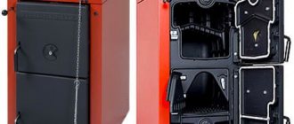
Wood-burning pyrolysis boiler: 1 - ash pan; 2 — fuel loading and gasification chamber; 3 - heat exchanger; 4 - combustion chamber; 5 — afterburning chamber; 6 - chimney
The design of every modern solid fuel boiler must provide for an additional air supply for combustion of the released gases. In this case, the intensity and rate of combustion of the fuel is regulated not by the volume of incoming oxygen, but by the heating temperature of the fuel. Indeed, if you heat the entire stack at once, flammable gases will be released very quickly and you will have to forget about the long operation of the boiler. However, if solid fuel is heated in separate portions, its gradual decomposition in the generator chamber and effective complete combustion in the second compartment of the furnace are possible. In this case, the flow of gases is inverted, they move from top to bottom under the influence of thrust created by ejection.
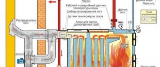
Design of a long-burning pyrolysis boiler: 1 - pyrolysis of solid fuel; 2 - combustion chamber; 3 - lower door; 4 — secondary air supply; 5 — primary air supply; 6 - upper loading door; 7 - gasification chamber; 8 - smoke exhauster
Budget option for a summer residence
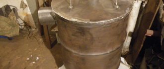
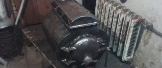
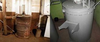
The gas cylinder, with its round shape and metal thickness, is excellent for making a pyrolysis boiler. It is almost a meter high and has a diameter of 35 cm. These dimensions are enough to create a heating device capable of heating a medium-sized room. The device burns well the most wasteful types of fuel: wood chips and sawdust, raw firewood.
The installation works as follows:
- load through the top or side door and set on fire;
- after a stable fire has arisen, cover with a piston (popularly called a pancake) and a tight lid in which there is a hole for the pipe;
- a limited amount of oxygen enters the firebox through the air duct, causing the pyrolysis process to begin;
- gases rise along the walls of the boiler and burn in the upper part;
- the remaining products are removed through the chimney.
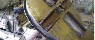
The balloon is cut at the point where the rounding begins. On the side there is a hole for the door, which should close very tightly. Therefore, it is usually used for cleaning, and fuel is loaded from above. The cut part is used for the lid:
- grind the cut to achieve a tight seal;
- make a hole 2–3 mm larger than the air duct pipe connected to the pancake;
- scalded at the bottom with a steel strip.
The piston has a unique design. Its blades are designed to swirl air currents over smoldering fuel, and a round piece of metal welded onto them prevents an open fire from occurring.
The chimney is made of pipes of different diameters: horizontal section - 120 mm, vertical section - 180 mm. This design helps create less active traction and inhibits the removal of gases. The right angle also plays a role in slowing down the combustion process. This ensures pyrolysis and continuous operation of the boiler for 8–10 hours.
A hole is made at the bottom for an ash pan with a door. Its design should ensure a tight fit. You can use a cut piece of the cylinder wall, onto which strip iron is welded around the perimeter. A grate welded from reinforcement is installed a little higher. Residues of fuel fall through it, which are then removed.
A lot of moisture condenses in the vertical chimney pipe, which collects in its lower part. A ball valve is installed to remove water. It is convenient because if it becomes clogged, it can be easily cleaned with a piece of wire.
Material of manufacture
Pyrolysis boilers are characterized by an increased temperature of the working area. There is no combustion in the gasification chamber, but the reverse heat flow is capable of heating the walls to 500–600 °C. The bottom of the gas generator compartment is exposed to the greatest temperature impact - it is this part that comes into contact with flammable gases and experiences a serious thermal load. It is recommended that the bottom of the filling chamber be made in the form of a cast iron grate or a special refractory product with a thin slot or a number of small holes.
The main difficulty in making boiler equipment yourself is choosing the appropriate grade of steel, which can be processed at home without special equipment. The most suitable in this regard are steels of the austenitic and austenitic-ferritic class with a moderate content of chromium and nickel. Examples of grades of such steels include 12Х18Н9Т, 08Х22Н6Т or AISI 304.
The technology for welding such metals is considered moderately complex, but reproducible in artisanal conditions using arc welding with coated electrodes without a protective environment. The main factor deteriorating the quality of a welded structure is the formation of hot and cold cracks, caused by a high temperature difference in a relatively small linear section of a metal product.
To eliminate the negative factors of thermal effects, the following technological methods are used:
- Cutting parts with a smooth feed of the cutting tool, which eliminates overheating of the edges.
- Limitation of welding current density by 20–25% compared to structural steel, welding in soft conditions.
- Limiting the temperature of the weld pool, performing a multi-pass weld at high speed without lateral vibrations.
- Correct cutting of the edges to be joined in accordance with GOST 5264 and their cleaning with a wire brush.
- Lining under the underside of the seam of a metal heat sink, forging the seam during the cooling process.
And, of course, the correct choice of the content of alloying additives in the electrode rod should be made in order to ensure a ferrite content in the weld structure of about 5–8%. Electrodes of the TsT-15 and TsT-16 brands, as well as special electrodes 6816 MoLC or ROST 1913, are recommended for use.
After welding the structures, it is recommended that they be initially annealed at a temperature of at least 700 °C for 2.5–3 hours. It is enough to load the inside of the welded body with coal and ignite the fuel, providing a weak forced air supply. Before annealing, it is advisable to pickle the welding seams with a special paste corresponding to the grade of steel used.
What fuel to use
For economical and efficient operation of the pyrolysis boiler, you can use any solid fuel: firewood, coal, peat, pellets, and other combustible materials. The main condition necessary to maintain the pyrolysis combustion process is low humidity, no more than 20%. Wetter fuel must be specially dried to the required level. The ability to use waste from wood, clothing, oil mills and other types of production makes this oven even more profitable to use. The wood content must be at least 70%.
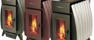
To operate a pyrolysis boiler, it is recommended to choose solid fuel
In conventional stoves, firewood needs to be added every two to three hours. Approximately 10 cubic meters of firewood are consumed in the winter. In pyrolysis boilers, wood burning lasts 12 hours, saving up to 40% over the winter. Coal burns much longer, up to five days, which saves not only fuel, but also time. There are models that are equipped with automatic feeding of fuel pellets, that is, they work in autonomous mode for a long time.
089aaee8336b4ccb28c7183ac916ddfa.jpe
Sizing and Power
Before you begin manufacturing a pyrolysis boiler, you should calculate the dimensions of the combustion chambers and additional compartments. The required calorific value is taken as the initial data, determined taking into account the efficiency of a homemade boiler of the order of 75–80%. At home, you can make solid fuel boilers with a power of up to 20–25 kW; more efficient units require the use of heat-resistant steel of considerable thickness, which is difficult to weld at home.
The power of the boiler and the duration of its operation are determined by the volume of the gasification chamber. Without taking into account efficiency, the calorific value of most common wood species is about 4–5 thousand kcal/kg, which approximately corresponds to 4–4.5 kWh of thermal power. These values only apply to wood with a moisture content of no more than 25%. The essence of the calculation is simple - determine the required instantaneous power and multiply it by the number of operating hours. It is worth remembering that pyrolysis boilers, even of advanced designs, have a maximum operating time of no more than a day, and self-produced units should be designed for a maximum of 12–15 hours of continuous burning.
The volume of the stowage chamber is determined at the rate of 2 liters for every kilogram of firewood. You need to add about 30% to the resulting value, because in the pyrolysis boiler they use non-split lumps that cannot be laid closely. The size of the gas combustion chamber must be at least 30–40% of the volume of the gasification chamber. The most advantageous structure is considered to be a boiler structure in which two chambers are located one above the other, have the same shape, but differ in height.
Performing Calculations
The first step is to select the size of the nozzle opening. The easiest way is to purchase a finished product designed for a certain power; these are available for sale for installations from different manufacturers, for example, ATMOS. Another way is somewhat more difficult, but much cheaper: make an opening of the required cross-section in fireclay bricks, which will be laid on the bottom of the firebox. The overall dimensions of the slot-shaped opening for different power values are presented in Table 1.
Table 1
| Required power, kW | 25 | 32 | 50 | 80 | 100 |
| Opening length, mm | 120 | 140 | 150 | 200 | 200 |
| Opening width, mm | 30 | 30 | 30 | 30 | 40 |
A homemade long-burning pyrolysis boiler can be made with arbitrary firebox sizes, which are calculated according to the following scheme:
- The heat of combustion of wood is 2.8 kW/kg, density is 400 kg/m3. To provide a power of 10 kW, you need to burn 10 / 2.8 = 3.6 kg of wood in 1 hour.
- Considering that there is empty space between the logs in the firebox, you need to take a fill factor of 0.5. Then the useful volume of the chamber for 1 hour of operation will be: 3.6 / 400 / 0.5 = 0.018 m3.
- Taking the log length to be 0.6 m and the height of the primary chamber to be 0.5 m, its useful width for 1 hour of work is calculated: 0.018 / 0.6 / 0.5 = 0.06 m.
- To load fuel once every 10 hours, the useful volume should be: 0.018 x 10 = 0.18 m3. Then, with the same depth and height values, the useful width will be: 0.18 / 0.6 / 0.5 = 0.6 m. The final dimensions are 0.6 m x 0.6 m x 0.5 m.
Homemade pyrolysis boiler
The next step is the selection of a fan - a supercharger, which is installed on homemade pyrolysis boilers and provides air supply to both chambers. Devices are selected according to performance, which depends on the power of the installation; this data can be taken from Table 2.
table 2
| Installation power, kW | 25 | 32 | 50 | 80 | 90 | 100 |
| Supercharger capacity, m3/h | 98,5 | 195,9 | 242,2 | 253,2 | 284,8 | 316,5 |
| Useful volume of the firebox, m3 | 0,22 | 0,24 | 0,35 | 0,42 | 0,47 | 0,52 |
The flue gases leaving the secondary chamber have a fairly high temperature. In order not to waste this heat on the street, a fire-tube scheme for manufacturing a pyrolysis boiler is used. In accordance with it, flue gases, passing through the smoke tubes of the heat exchanger, are cooled to a temperature of 150–200 ⁰C, giving up their heat to the water jacket. To calculate the useful heat exchange area, you need to determine the following initial data:
- coolant temperature in the supply and return pipelines t1 and t2;
- temperature of the flue gases at the entrance to the heat exchanger and at the exit from it T1 and T2.
Next, the temperature difference ∆t = t1 - t2 and ∆T = T1 - T2 is determined. After this, you can calculate the temperature difference τ, ⁰С:
τ = (∆T - ∆t) / ln (∆T / ∆t)
The heat exchange surface area S(m2) is found by the formula:
S = Q / k / τ
In this formula:
- Q – required power of the boiler installation;
- k is the heat flow transfer coefficient, assumed to be 30 W/m2 ⁰С.
You can check the result using Table 3, which presents aggregated values of the heat exchange surface area depending on the power of the unit.
Table 3
| Boiler power, kW | 25 | 32 | 50 | 80 | 100 |
| Smin, m2 | 4,5 | 6,3 | 8,5 | 14,5 | 16,5 |
| Smax, m2 | 5,2 | 7,8 | 10,2 | 15,2 | 16,7 |
When making long-burning pyrolysis boilers with their own hands, craftsmen often install the chimney pipe “by eye,” while the efficiency of the unit itself depends on the correct operation of the chimney pipe. Therefore, the cross-sectional area of the pipe, and then its diameter, is better determined by the formula:
F = L / 3600ϑ
In this formula:
- ϑ – flue gas velocity, assumed to be 0.5 m/s;
- L – gas flow, corresponds to the fan performance, m3/h;
- F – cross-sectional area of the chimney pipe, m2.
Using the formula for the area of a circle, the diameter of the pipe is found.
Assembling a two-chamber firebox
It is better to choose a hot-rolled sheet with a thickness of at least 8 mm, ideally 10–12 mm, as the material for making the chamber walls. The thicker the metal, the more difficult the welding process, but a structure made of too thin steel is guaranteed to move and twist in unpredictable directions. That is why among the parts from which the boiler is assembled there should not be small elements with an aspect ratio of more than 2:1.
The basis of a two-chamber firebox is the outer side walls. They are common to both chambers and are connected through the front wall, in which two rectangular holes are made for the doors. The lower hole is intended for servicing the combustion chamber, its height should be about 120–150 mm, width - at least 300 mm, the hole is located at a distance of 150 mm from the bottom edge. The upper hole is intended for loading the gasification chamber; the larger it is, the better; the hole should be located no closer than 100 mm to the top of the chamber. From below and at the back, the firebox is closed with solid sheets, which are cut to fit the external dimensions of the combustion chamber, but are not welded until the internal parts are assembled. The top of the boiler is covered with a sheet of nominal cross-section.
Example of dimensions of a pyrolysis boiler
The gasification and combustion chambers will be separated by a solid plate, the width of which corresponds to the internal distance between the walls, and the length is 400 mm less. At the back of the plate, a solid partition is welded vertically, which separates the loading chamber along its entire height; a hole 50 mm wide and 400–600 mm long is cut in the center along the horizontal part. The assembled L-shaped partition is not welded until the heat exchanger assembly is completed.
Heat exchanger for pyrolysis boiler
The best configuration for the heat exchanger of a homemade pyrolysis boiler will be the water jacket of the lower chamber and the chimney duct. This is not the most efficient type, however, producing your own honeycomb heat exchanger will cause inevitable difficulties either with finding pipes of the appropriate grade of steel, or with welding dissimilar parts.
The assembly of the heat exchanger parts is carried out at the stage when the bottom, front panel and two side walls of the boiler are welded. Access for welding work is provided from the rear of the boiler. The first step is to install the upper partition of the shirt. This is a rectangular plate along the internal width of the firebox and is 200 mm less than the depth of the combustion chamber. On the sides of the slab, two rectangular fragments 100 mm wide must be removed so that two protrusions 200 mm long remain in the front part of the slab. The resulting part is welded to the walls and front panel flush with the lower edge of the combustion chamber door opening. In this case, the cutouts in the partition form channels for circulation between the lower zone and the side walls of the heat exchanger.
The inner walls of the jacket are made along the edge of the flow channels, have the height of the combustion chamber and are adjacent closely to the front panel. They are covered on top with two strips 100 mm wide.
The length of the heat exchanger does not reach the rear wall of the boiler by about 200 mm, and the side channels protrude beyond the L-shaped partition between the chambers by approximately the same distance. When it is installed, all that remains is to form double walls of the chimney duct, cut out its outlet, secure the back wall of the boiler and cut in threaded fittings for connection to the heating pipeline. The return is inserted into one of the front lower corners of the jacket; the supply is inserted at any highest point of the chimney jacket.
Please note that the combustion chamber is limited on all sides by a water jacket, except for the partition with the gasification chamber. This is necessary for the transfer of heat, which ensures thermal decomposition of the fuel. In this case, not the entire filling will be heated at once, but only its layers adjacent to the heated walls.
Suitable waste for recycling
The advantage of pyrolysis plants is that they are suitable for the safe disposal of a wide range of materials, including difficult to decompose substances.
- Solid waste: paper, plastic, glass, bones, etc.;
- wood processing waste: chips and sawdust;
- plastic and polymer-containing waste (bottles, plastic bags);
- silt layers formed in sewers and sewers;
- slate and peat;
- car tires, rubber waste;
- waste from the agricultural and industrial complex;
- agricultural waste (husks of grains, shells of nuts, etc.);
- waste from medical institutions
- oil sludge;
- plant waste, including algae.
Optional equipment
Unfortunately, pyrolysis boilers are not energy independent. Due to the reverse flow of gases, forced charging is required. For models with a power of up to 15 kW, it is implemented by a blower fan, which is mounted on the bottom door. In this case, replenishing the load during the combustion process is impossible.
More powerful boilers are equipped with a smoke exhaust fan, which is installed on the upper wall of the housing at the outlet of the chimney duct. In this case, the appearance of reverse draft is eliminated and the door of the gasification chamber can be opened without consequences even during the combustion process.
Particular attention should be paid to the temperature of the coolant inside the jacket. After the boiler returns to operating mode, it should not be less than 60 °C to prevent the formation of condensation. This problem is solved by installing an automatic recirculation unit that mixes water from the supply to the return. Installation of a safety group for closed heating systems and the main circulation pump is also required. published
PS And remember, just by changing your consumption, we are changing the world together! © econet
Making a device with your own hands: step-by-step instructions
The high cost of a factory-made pyrolysis boiler encourages craftsmen to build copies of factory-made boilers with their own hands or independently search for innovative technical solutions. The process of building such equipment is complex, but interesting.
Selecting a diagram and drawing
Before starting work, the most important stage is choosing a project . If possible, it is worth purchasing a ready-made project that has already been tested, so as not to make mistakes from your own experience.
Photo 2. Scheme of self-assembly of a pyrolysis boiler with a chimney duct and an upper loading door.
Things to consider when designing and creating a drawing:
- Burner power. It depends on the area of the primary combustion chamber and the size of the firebox, as well as on the intensity of oxygen injection.
- Firebox size. It determines how much fuel will be filled, which means how long the boiler will operate without recharging.
- Type of boost. There are natural draft boilers, but they do not provide stable combustion of gases. Both a boost fan and a smoke exhauster can be installed on the boiler.
- Type of heat exchanger. The escaping heat must be effectively captured. A water jacket or plate heat exchanger on the exhaust will do the job well.
- Lining of the primary and secondary chamber , as well as the method of regulating the primary and secondary air.
Photo 3. An example of a drawing of a long-burning pyrolysis boiler with the indicated dimensions. Side and front view.
Materials and tools
To build a pyrolysis boiler with our own hands we will need:
- Sheets of high-alloy steel 4 mm thick. They are easier to weld and will not burn out from high temperatures.
- Forced-air fan and automation.
Reference! The more expensive option is a factory fan and a smooth control controller, the cheaper option is a car heater fan, a step regulator and a simple gate for precise adjustment.
- Lining material. The secondary combustion chamber must be lined with a refractory layer, since the combustion temperature of pyrolysis gases is 1200 °C . This could be kaolin wool or fireclay brick.
- Pressure and temperature sensor.
- Pipes, fittings, rods, curtains, valve ball, heat-resistant paint.
To build a boiler, you need an equipped plumbing workshop. The craftsman will need skills in marking and fitting parts, the ability to read blueprints and cut metal.
- Tools for processing and joining metal. Angle grinder, welding machine, electrodes. Ideally, the parts will be cut to order on a CNC laser machine - this will add beauty and make the task easier.
Attention! Follow the rules for safe use of tools. Monitor the integrity of the wire insulation, watch the direction of the sparks when cutting metal.
- Measuring instruments: compass, ruler, angle, tape measure.
- Tools for processing fireclay bricks: angle grinder disc with carbide tips.