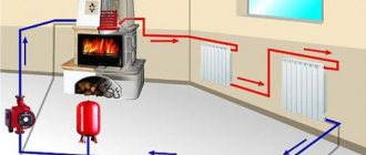
The uniform distribution of heat in a house with an autonomous heating system is determined by the model of pumping device used. This equipment ensures the forced movement of a warm medium through pipes and radiators.
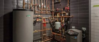
To determine which heating pump connection diagram will be optimal for independent implementation, many details must be taken into account. In this article, we will consider in detail possible connection schemes and analyze the connection rules in detail.
We will also pay attention to the subtleties of choosing a location for installation, supplementing the material with thematic photos and diagrams.
Pros and cons of using a heating pump
Just a couple of decades ago, in the private sector, houses were equipped with gravity-type heating. A wood stove or gas boiler was used as a heat source. There was only one area of application left for large circulation devices - centralized heating networks.
Today, manufacturers of heating equipment offer smaller units that have the following advantages:
- The speed of movement of the coolant has increased . The heat generated by the boiler quickly enters the radiators. Due to this, the process of warming up the premises was significantly accelerated.
- The higher the movement speed, the higher the pipe capacity . This means that an identical volume of heat can be delivered to rooms using a pipe with a smaller diameter.
- Water heating schemes have undergone significant changes . The highway can be laid with the slightest slope. Also, the complexity and length of the line can be anything. The basic rule is the rational choice of a heating pump based on the required power.
- With the help of a household circulation device, it became possible to organize heated floors in the house, as well as an effective closed-type heating system.
- It became possible to hide the entire heating communication line passing through the rooms, which does not always go well with the design of the room. Options for laying pipes behind suspended ceilings, in walls or under floor coverings are quite common.
The disadvantages of pumping systems include the dependence of operation on the supply of electricity and its consumption by the pumping apparatus during the heating season.
The leading company Grundfos, engaged in the development of heating equipment, has released innovative models of Alpfa2 circulation pumps, capable of changing performance based on the needs of the heating system, which allows saving on electricity consumption
Therefore, if the area is often deprived of power supply, it would be advisable to install a device to provide uninterrupted power. The second drawback is not critical and can be eliminated by correctly selecting the power and model of the circulation pump.
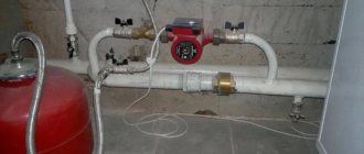
Selecting the location for inserting the device into the system
The installation of the circulation pump is supposed to be in the area immediately after the heat generator, not reaching the first branch line. The chosen pipeline does not matter - it can be either a supply or a return line.
Where can I put the pump?
Modern models of household heating units, made of high-quality materials, can withstand temperatures of a maximum of 100 °C. However, most systems are not designed for higher heating of the coolant.
The temperature of the coolant in the personal heating network rarely even reaches 70 °C. The boiler also does not heat the water above 90 degrees
Its performance will be equally effective on both the supply and return branches.
And that's why:
- The density of water when heated to 50 °C is 987 kg/m3, and at 70 degrees – 977.9 kg/m3;
- The heating unit is capable of generating hydrostatic pressure of 4-6 m of water column and pumping almost 1 ton of coolant per hour.
From this we can conclude: the insignificant difference of 9 kg/m3 between the statistical pressure of the moving coolant and the return does not affect the quality of space heating.
Are there exceptions to the rules?
As an exception, inexpensive solid fuel boilers with a direct combustion type can serve. Their device does not provide automation, so at the moment of overheating, the coolant begins to boil.
Installation of collector wiring in a heating system using a solid fuel boiler is considered the most effective. However, this type of heating of a private house is one of the most difficult to perform.
Problems begin to arise if the electric pump installed in the supply line begins to fill with hot water and steam.
The coolant penetrates through the housing with the impeller and the following occurs:
- Due to the action of gases on the impeller of the pumping device, the efficiency of the unit decreases. As a result, the coolant circulation rate coefficient is significantly reduced.
- An insufficient amount of cold liquid enters the expansion tank located near the suction pipe. The overheating of the mechanism increases and even more steam is formed.
- A large amount of steam entering the impeller completely stops the movement of warm water along the line. Due to the increase in pressure, the safety valve is triggered. Steam is released directly into the boiler room. An emergency situation is being created.
- If the firewood is not extinguished at this moment, the valve will not be able to cope with the load and an explosion will occur.
In practice, no more than 5 minutes pass from the initial moment of overheating to the activation of the safety valve. If you install the circulation mechanism on the return branch, then the period of time during which steam enters the device increases to 30 minutes. This gap will be enough to eliminate the heat supply.
In inexpensive heat generators made of low-quality metal, the response pressure of the safety valve corresponds to 2 Bar. In high-quality solid fuel boilers - this indicator is 3 Bar
From this we can conclude that it is impractical and even dangerous to install a circulation device on the supply line. Pumps for solid fuel heat generators are best installed in the return pipeline. However, this requirement does not apply to automated systems.
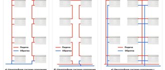
Heating with a group of separate lines
If the heating system is divided into two separate lines, heating the right and left sides of the cottage or several floors, it would be more practical to install an individual pump for each of the branches.
When installing a separate device for the heating line on the second floor, it becomes possible to save money by adjusting the required operating mode. Due to the fact that heat has the property of rising, it will always be warmer on the second floor. This will reduce the coolant circulation rate.
The pump is inserted in the same way - in the area located immediately after the heat generator before the first branch in this heating circuit. Typically, when installing two units in a two-story house, fuel consumption for servicing the upper floor will be significantly less.
Schemes for different types of systems
Initially, it is necessary to determine the insertion area of the circulation device. With its help, the process of active movement of liquid is carried out - the flow passes through the boiler and is forcibly directed to the heating radiators.
To locate a household pump, it is necessary to determine the most convenient area so that it can be easily serviced. On the supply side, it is installed after the safety block and shut-off valves of the boiler.
In order to carry out maintenance and control the functioning of equipment, it is necessary to install shut-off valves. Thus, any element of the heating system can be removed without completely dismantling the line
On the return pipeline, the pump is placed after the expansion tank in front of the heat generator.
Due to the presence of various mechanical impurities in the water, for example, sand, problems may arise in the operation of the pumping mechanism. Particles contribute to jamming of the impeller, and in the worst case, stopping the motor. Therefore, you will need to install a strainer strainer directly in front of the unit.
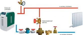
The connection diagram for a solid fuel boiler is based on two important elements that allow it to function effectively in the heating system of a private home. These include: a safety group and a mixing unit based on a three-way mixing valve
Separately, it is worth mentioning the issue of an open-type heating system. It is capable of operating in two modes - with forced and gravity coolant circulation.
The second option is more suitable for areas with frequent power outages. This is much more economical than purchasing an uninterruptible power supply or generator. In this case, the unit with shut-off valves must be installed on the bypass, and a tap must be inserted into the direct line.
In stores you can find ready-made units with a bypass. In place of the flow tap, there is a spring-loaded non-return valve. This solution is not recommended - the valve produces a resistance force of 0.1 Bar, which is considered a large indicator for a gravity-type circulation system.
It is better to use a reed valve instead. However, its installation is carried out strictly horizontally.
Popular factory models
You can choose the right UPS both in online stores and in specialized super markets that sell accessories for heating equipment or plumbing. The choice is of course yours. And we will give only some popular models and their approximate cost.
Energy PN-1000
Energy PN-1000 is a fairly powerful device that is capable of providing uninterrupted power supply for boiler appliances. Recommended for use in a set with 100 A/h batteries. Designed to work with low-power (150 W) pumps. This device can last 9 hours offline. With a smooth sinusoid type output signal. There is a pre-installed network interference filter. For informational purposes, the front panel is equipped with a display. With a fairly high efficiency, the price for this model is 26,100 rubles.
SVC DI-600-F-LCD
Designed to support the operation of boilers and pumping stations in autonomous mode. The response speed is 15 microseconds. When using external storage units with a capacity of up to 200 A/h, the pump will operate continuously for up to 24 hours. The peak load on the uninterruptible power supply is no more than 360 W. Does not require systematic maintenance. This modification will cost about 7 thousand rubles.
Tieber T-1000
Tieber T-1000 can maintain the operation of the heating system for at least 48 hours in the event of a centralized power supply interruption. For operation, it is recommended to use a pair of gel batteries, each with a capacity of 200 Ah. Withstands peak loads up to 800 W. The output waveform is a pure sine wave. Price - 15,100 rubles.
Solid fuel pump and boiler
The pump is connected to the system with a solid fuel unit on the return line. In this case, the pumping device is connected to the boiler circuit with a bypass and a three-way mixing valve. In addition, the latter can be equipped with a servo drive and an overhead temperature sensor.
The connection diagram for a solid fuel boiler is based on two important elements that allow it to function effectively in the heating system of a private home. These include: a safety group and a mixing unit based on a three-way mixing valve
Due to the fact that the maximum performance of heating equipment is used to its fullest extent only during the cold period, it is possible to install a heat accumulator (TA). It is able to absorb excess heat and then, on demand, release it to the heating circuit.
This battery is made in the form of a tank and is lined with thermal insulation material. On one side of the device there are two pipes intended for connecting it, and two on the other - for connecting to the radiator line.
The heat accumulator has two circuits: small and large. The first one receives energy from the boiler, the second one supplies coolant to the heating system as needed.
As the liquid passes through the boiler, which operates at maximum, the coolant in the heat accumulator warms up over time to 90-110 degrees. In a large circuit, the insertion of another circulation device is required.
Depending on the degree of cooling of the liquid in the heating system, the required amount of heat from the storage device will enter through the valve.
Video description
The video will show how to extend the cable of a well pump using heat shrink sleeves:
Without coupling
Some well head designs have a special terminal block. It allows you to avoid couplings when connecting the cable to the pump. To use it, you need to prepare the ends of the wires in the usual way. That is, strip the insulation approximately 10 mm from the edge.
Then the cores are inserted into the block according to the principle - a friend opposite a friend. The clamping bolt ensures reliable contact. But if you tighten the fastener too much, you can flatten the core into small wires and thereby weaken communication.
And when the bolt is not tightened enough, sparking occurs in the terminal block. At the same time, oxidation processes begin. And over time, the block itself may melt. Therefore, experienced plumbers prefer not to use a retrofitted head. And they use one of the methods with couplings.
Pump installation diagram
To perform its functions, household circulation equipment, regardless of the manufacturer, must be correctly installed on a pipe or shut-off and control valves.
Fastening is done using union nuts. This fixation option will allow you to remove it if necessary, for example, for inspection or repair.
When choosing a circulation pump model, you need to pay attention to its ability to function in different positions. Vertical placement of the device reduces its power by up to 30%
Correct installation of all elements of the heating system ensures uniform heating of the entire line.
When installing the circulation pump, the following rules must be observed:
- It is allowed to install the device on any section of the pipe. The pipeline can be located horizontally, vertically or inclined. However, the rotor axis must be in a horizontal position. Therefore, installation “head down” or, conversely, up is impossible.
- It is worth paying close attention to the location of the plastic box where the power supply contacts are located - they will be on top of the body. Otherwise, they may be flooded with water in an emergency. To do this, you will need to unscrew the fastening screws on the casing and turn it in the required direction.
- Observe the direction of flow. It is indicated by an arrow on the device body.
With all its weight, the pump presses on the body of the ball valves located nearby. This should be taken into account when choosing fittings. High-quality parts are equipped with a powerful body, which during operation will not become cracked from daily stress.
Briefly about the main thing
When choosing a cable for submersible pumping equipment, you need to pay attention to three points:
- Is the wire cross-section sufficient to connect the pump to a remote power source?
- Is the stated insulation on it truly waterproof?
- Does the product have a certificate confirming the possibility of its use in drinking wells?
To check the last two points, you will have to carefully study the technical documentation that comes with the cable. You need to find the required core cross-section yourself. To do this, the distance between the pump and the power source is accurately measured. Then they use either tabular data or make exact calculations using formulas.
Installation of additional equipment
Regardless of the type of heating circuit used, where one boiler serves as the heat producer, it will be sufficient to install a single pumping device.
If the design of the system is more complex, it is possible to use additional devices that provide forced circulation of liquid.
An example of a joint wiring diagram for a solid fuel boiler paired with an electric one. This heating system has two pumping devices
This becomes necessary in the following cases:
- when heating a house, more than one boiler unit is involved;
- if there is a buffer capacity in the piping scheme;
- the heating system diverges into several branches, for example, servicing an indirect boiler, several floors, etc.;
- when using a hydraulic separator;
- when the pipeline length is more than 80 meters;
- when organizing water movement in floor heating circuits.
To perform the correct piping of several boilers operating on different fuels, there is a need to install backup pumps.
For a circuit with a heat accumulator, the installation of an additional circulation pump is also required. In this case, the main line consists of two circuits - heating and boiler.
The buffer tank divides the system into two circuits, although in practice there may be more of them
A more complex heating scheme is implemented in large houses with 2-3 floors. Due to the branching of the system into several lines, 2 or more pumps are used to pump the coolant.
They are responsible for supplying coolant to each floor to various heating devices.
Regardless of the number of pumping devices, they are installed on the bypass. In the off-season, the heating system can operate without a pump, which is shut off using ball valves
If you plan to install heated floors in the house, then it is advisable to install two circulation pumps.
In the complex, the pumping and mixing unit is responsible for preparing the coolant, i.e. maintaining the temperature at 30-40 °C.
In order for the power of the main pumping device to be sufficient to overcome the local hydraulic resistance of the floor contours, the length of the line should not be more than 50 m. Otherwise, the heating of the floors will become uneven and, accordingly, the rooms
In some cases, the installation of pumping units is not required at all. Many models of wall-mounted electric and gas generators already have built-in circulation devices.
Rules for connecting to power supply
The circulation pump is powered. The connection is standard. It is recommended to install a separate power supply line with a surge protector.
To connect, you need to prepare 3 wires - phase, neutral and ground.
You can choose any of the connection methods:
- through a differential machine device;
- connection to the network together with an uninterruptible power supply;
- power supply to the pump from the boiler automation system;
- with thermostat regulation.
Many people wonder why complicate things, because connecting the pump can be done by connecting a plug to a wire. This is how the pumping device is plugged into a regular outlet.
However, experts do not recommend using this method due to the risk of unforeseen situations: there is no grounding and a safety device.
A circuit with a differential machine is used for so-called wet groups. A heating system constructed in this way ensures a high degree of safety for wiring, equipment and people.
The first option is not difficult to assemble yourself. It is necessary to install an 8 A differential circuit breaker. The wire cross-section is selected based on the device rating.
In the standard scheme, the power supply is carried out to the upper sockets - they are marked with odd numbers, the load - to the lower ones (even numbers). Both phase and neutral will be connected to the machine, so the connectors for the latter are designated by the letter N.
To automate the process of stopping the circulation of the coolant when cooling to a certain temperature, an electrical circuit is used to connect the pump and thermostat. The second is mounted in the supply line.
At the moment when the water temperature drops to the specified value, the device disconnects the electrical supply circuit.
In order for the thermostat to turn off the circulation process at the right time, it is installed on a metal section of the pipeline line. Due to poor heat conductivity of polymers, installation on a plastic pipe will result in incorrect operation of the device
There are no difficulties in supplying electricity through an uninterruptible power supply; it has special connectors for this. A heat generator is also connected to them when there is a need to provide electricity.
If you choose the method of connecting the pump to the boiler control panel or automation, you will need good knowledge of the power supply system or the help of a professional.
Selection of section
The thickness of the conductor is very important. Its correct choice determines how productive the equipment will work. If the core cross-section is insufficient, then the resistance in the electrical circuit will begin to increase. This will lead to the fact that part of the power will be spent on heat generation (heating the core).
This will affect the productivity of the pump. Receiving less power, it will not deliver its maximum capabilities. The insulation of the wires will also be damaged. A gradual drying process will reduce the protective properties. And this is fraught with a short circuit.
To calculate the cross-section, you need to know the following parameters:
- Power consumption of pumping equipment during operation.
- Current load of the pump.
- Distance from pump to power source.
- The nature of the electrical network (single-phase or three-phase).
Tabular data
The easiest way to find the required wire cross-section for a well pump is to refer to ready-made tabular data. There are many of them in various reference books. And they quite accurately indicate all the necessary parameters. Two of them can be seen in the photo provided.
Table for calculating cables for wells Source uk-parkovaya.ru
Knowing the power consumption of your pump and the distance to the power source, it is not at all difficult to find the required wire cross-section in the table. For example, if with an electric motor power of 1.1 kW it is necessary to connect it to a single-phase electrical panel located 60 meters away, then for this you will need a cable with a core cross-section of 2.5 mm2.
And then electricians have simple rules. When connecting to a single-phase network, a three-wire cable is used, and when connecting to a three-phase network, a four-wire cable is used. In the first case, when the distance to the power source increases for every 10 meters, the cross-section must be increased by 0.5 mm2.
And when using a pump of the above power, to the shield located at a distance of 70 meters, you already need to take a cable with a wire cross-section of 3 mm2. And if the length of the line reaches 100 meters, you will need a core with a cross-section of 4 mm2. It should not be forgotten that the cross-section of the wire is the area of the net diameter of the core itself, without insulation. Moreover, it should not be confused with the thickness of the cable itself.
Core cross-section Source bassclub.ru
For a three-phase motor with the same power, you will need a core with a cross-section of only one square millimeter, but the cable must be four-core. Moreover, the highway can be extended over a distance of up to 200 meters. And beyond this length, use a wire with an area of 1.5 mm2.