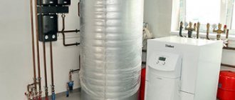
Internal technological circuits
- Heating of the boiler room is an adjustable circuit for radiators.
- Ventilation of the boiler room is an independent circuit through a plate heat exchanger with heating of the non-freezing coolant.
- Combustion air heating is an independent circuit through a plate heat exchanger with heated non-freezing coolant.
The scheme also provides for a cold water input, a booster pumping station, a water treatment unit and a make-up water storage tank.
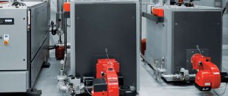
Boiler and hydraulic distribution device
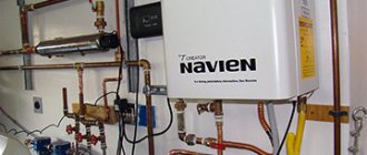
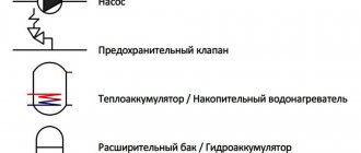
A boiler unit is a fully factory-ready product that includes a boiler, burner, circulation pump, control and shut-off valves, safety valves, thermometers, pressure gauges, temperature and pressure sensors connected to the automation system.
The boiler unit automation collects data from temperature sensors on the boiler supply pipe, as well as from a strategy sensor installed in the hydraulic pointer, and regulates the boiler power with the burner. Sensors are installed on the supply pipeline that limit the maximum temperature of the coolant at the outlet of the boiler. Based on the temperature sensor at the entrance to the boiler, the automation organizes protection of the boiler from cold coolant.
A three-way mixing valve on the return pipeline mixes coolant from the supply pipeline, increasing the temperature at the inlet to the boiler until it reaches the minimum required value. This prevents condensation from the flue gases, which leads to corrosion of the boiler. The advantage of a three-way mixing valve is its ability, if necessary, to completely shut off the flow of cold coolant, closing the boiler to internal circulation until it is heated to the minimum required temperature. This operation of the three-way mixing valve implies variable flow in the boiler circuit. To stabilize it, it is necessary to provide a hydraulic arrow that separates the hydraulics of the boiler circuit and the consumer circuit (or the heating circuit of the heat exchangers), stabilizing a possible imbalance of costs.
Minimum and maximum pressure sensors are installed on the boiler supply pipe, turning off the burner when the pressure decreases or increases. A decrease in pressure can cause boiling of the coolant; an increase can cause a violation of the integrity of the boiler. As additional protection against overpressure, safety valves are installed on the boiler that release coolant from the boiler, thereby reducing the pressure in it.
The circulation pump of the boiler unit works continuously when the burner is operating. When the burner and the entire boiler unit are switched off, the pump also switches off after a certain time and the three-way mixing valve switches to the internal circulation position. This ensures that there is no coolant circulation through the idle boiler.
To compensate for thermal expansion of the coolant, a membrane expansion tank is connected to the boiler drain pipe. As the temperature of the coolant increases and, as a consequence, its volume increases, the expansion tank accumulates excess coolant. When the temperature drops, the reverse process of coolant transfer from the tank to the boiler occurs, preventing vacuum in it.
The choice of the boiler drain pipe is determined by the fact that this is the point with the lowest temperature. An expansion tank with an intermediate cooling tank and a safety valve is installed on a common manifold from the boiler units. The expansion tank accumulates thermal expansion of the boiler circuit coolant. It is connected to the return manifold through an intermediate cooling tank, where the coolant is additionally cooled, which extends the service life of the expansion tank. To protect the expansion tank from overpressure, a safety valve is additionally installed.
The boiler units operate in a cascade. One of the boilers is assigned as the master (MASTER), the other as the slave (SLAVE). The lead boiler is always in operation. When it reaches maximum power and a request to increase power comes, the slave boiler is switched on.
The hydraulic distribution device is a cylindrical vessel with four connections:
- hot coolant inlet from boilers,
- outlet of cold coolant to boilers,
- outlet of hot coolant to consumers,
- cold coolant inlet from consumers.
At the outlet of the hot coolant, a strategy sensor is installed on consumers, through which the power of the boilers and the number of operating boilers are controlled. An air vent is installed in the upper part of the hydraulic needle, and a drain valve is installed in the lower part. For optimal operation of the hydraulic needle, it is necessary that the coolant flow from the boilers exceeds the coolant flow from consumers by at least 35%. The difference in flow rates flows along the body of the hydraulic needle from the inlet to the outlet on the side of the boilers.
Water heating boiler design
Types of water heating boilers for home and industrial use
The fundamental design of heating devices is approximately the same and may differ in such indicators as fuel consumption, power, size and country of origin.
A standard water heating boiler consists of the following parts:
- steel body;
- burner;
- wick;
- inlet pipes (located at the bottom);
- outlet pipes (located on top of the body);
- steam valve;
- the combustion chamber;
- water heat exchangers;
- firebox with door;
- blower with handle;
- chimney with valve and protective cap.
The firebox of solid fuel boilers is equipped with grates designed to accommodate fuel and drain waste products (slag, ash, ash) into the ash pan.
The operating principle of water heating boilers is as follows:
- loading fuel into the firebox and setting it on fire (connecting an electric heating element);
- filling the circuit and heat exchanger with water;
- the liquid heats up and, under the influence of a pump or due to a pressure difference, moves by gravity through the pipes;
- combustion products are discharged through a conventional or coaxial chimney;
- the valve regulates the supply of air necessary for combustion of the fuel.
The boilers are made of durable heat-resistant steel that can withstand high temperatures.
DHW circuit
It is an independent circuit separated by a heat exchanger. On the heating side of the supply pipeline, a three-way mixing valve is installed, which maintains a constant temperature at the inlet to the heat exchanger according to the temperature sensor upstream of the heat exchanger. The temperature is maintained by mixing coolant from the return pipe from the heat exchanger. This means that the temperature at the outlet of the hydraulic needle must always be higher than or equal to the temperature of the DHW heating circuit.
A circulation pump with a frequency drive is installed on the heating side in the return pipeline. Using a temperature sensor installed on the DHW supply pipeline, the frequency of the circulation pumps of the heating circuit is adjusted, and with it the flow rate on the heating circuit of the DHW heat exchangers (quantitative adjustment). When the DHW temperature decreases, the frequency on the pumps increases, and when the temperature increases, the frequency decreases.
The pressure in the DHW circuit is maintained by a booster pumping station at the cold water inlet.
DHW circulation is ensured by a circulation pump on the DHW return pipeline. The pump is equipped with a frequency controller and is controlled by the temperature in the DHW return pipe. If the circulating water from DHW consumers returns hot, the pump reduces the frequency, thereby reducing consumption. If circulating water from DHW consumers returns cold, then the frequency increases and so does the flow rate.
To compensate for temperature expansion of the hot water supply, an expansion tank is provided, equipped with a safety valve that protects the tank from excess pressure.
Pumps, fittings, pipelines and heat exchanger connections on the heated side of the hot water supply are made of corrosion-resistant materials, since deaeration of the initial cold water is not provided.
At the outlet of the boiler room on the DHW circuit, a heat metering unit is installed, which records the thermal energy supplied to consumers.
Classification by type of accommodation
Wall-mounted water heating boilers have a relatively small weight, in contrast to floor-standing models.
Water heating devices, depending on the power and design, have different weights and sizes. This largely determines the place where they can be installed.
Floor products are characterized by significant weight and dimensions. It is impossible to hang them precisely because of these factors, since not every load-bearing surface can withstand such a load. The advantage is that such devices are more reliable and functional.
Wall-mounted boilers are compact and light in weight. Their development was initially aimed at ensuring that the products could be installed in tight spaces - kitchen, bathroom, basement. Due to size restrictions, such boilers are not designed for high power; the close arrangement of parts makes them difficult to service and reduces the level of reliability.
Adjustable heating (ventilation) circuit
A three-way mixing valve is installed on the supply pipeline, maintaining the set temperature for the consumer circuit. The temperature is maintained by mixing coolant from the return pipeline. This means that the temperature at the outlet of the hydraulic needle must always be higher than or equal to the temperature on the consumer circuit.
A circulation pump is installed on the return pipeline, which ensures the circulation of coolant among consumers. The pump runs as long as the constant flow circuit is on.
To compensate for temperature expansions in the heating (ventilation) circuit, an expansion tank is provided, equipped with a safety valve that protects the tank from excess pressure.
At the outlet from the boiler room on the heating (ventilation) circuit, a heat metering unit is installed, which keeps track of the thermal energy supplied to consumers.
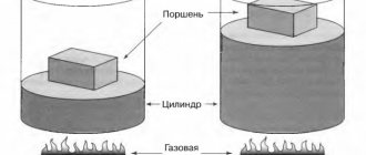
Where does pure hydrogen come from?
Note to the owner
“To attract attention to their products, some hydrogen boiler manufacturers make references to some kind of “secret catalyst” or to the use of “Brown gas” in their devices.” For example, you can extract hydrogen from methane gas, where there are as many as 4 atoms of hydrogen! But why? Methane itself is a flammable gas, so why waste additional energy to produce pure hydrogen? Where is the energy efficiency? Therefore, hydrogen is most often extracted from water, which, as everyone knows, cannot burn, using the electrolysis method.
In its most general form, this method can be described as the splitting of water molecules into hydrogen and oxygen under the influence of electricity
For example, you can extract hydrogen from methane gas, where there are as many as 4 atoms of hydrogen! But why? Methane itself is a flammable gas, so why waste additional energy to produce pure hydrogen? Where is the energy efficiency? Therefore, hydrogen is most often extracted from water, which, as everyone knows, cannot burn, using the electrolysis method. In its most general form, this method can be described as the splitting of water molecules into hydrogen and oxygen under the influence of electricity.
Electrolysis has long been known and widely used to produce pure hydrogen. In practice, not a single industrial hydrogen boiler, at least for now, can do without an electrolysis installation or electrolyzer. Everything would be fine, but this installation requires electricity. So, a hydrogen boiler must necessarily consume energy. The question is, what are these energy costs?
Electrolysis process diagram
All the talk about the “heat of combustion” of hydrogen takes us a little away from this issue, and yet it is the most important. So, a hydrogen boiler can be beneficial in the only case - the thermal energy it produces must be higher than that expended on the operation of the boiler.
Unregulated heating (ventilation) circuit
There are no control valves on this circuit. This means that the temperature in the circuit will be equal to the temperature at the outlet of the hydraulic needle.
A circulation pump is installed on the return pipeline, which ensures the circulation of coolant among consumers. The pump runs all the time while the circuit is on, with a constant flow rate.
To compensate for temperature expansions in the heating (ventilation) circuit, an expansion tank is provided, equipped with a safety valve that protects the tank from excess pressure.
At the outlet from the boiler room on the heating (ventilation) circuit, a heat metering unit is installed, which keeps track of the thermal energy supplied to consumers.
Popular models
To conclude the material, we will consider the most popular brands of water heating devices from leading manufacturers that are in greatest demand in the plumbing market.
Beretta
An Italian company that produces all types of heating boilers produces high quality products. The performance of the equipment is checked during testing under extreme conditions, which help to identify the weak points of the devices.
Popular models:
- Compact;
- Ciao;
- City.
Ferroli
An international concern, originally created in Italy, specializes in the production of domestic and industrial boilers. Thanks to the quality of its products, it has been a leader in the heating systems market for many years.
Popular models:
- Domina;
- Arena.
Bosch (Bosch)
Reliable German boilers that can function in combination with a solar collector.
Popular models:
- Gaz 4000 ZWA;
- WBN6000-24C RN.
Proterm
The Czech company produces high-quality products that are exported to 25 countries. Gas boilers have a modern design, low noise level and affordable price.
Popular models:
Adjustable radiator heating circuit for boiler room
This circuit is the internal circuit of the boiler room, the heat from which is used for its own needs.
A three-way mixing valve is installed on the supply pipeline, maintaining the set temperature on the radiators with adjustment to the temperature inside the boiler room. The temperature is maintained by mixing coolant from the return pipeline. This means that the temperature at the outlet of the hydraulic needle must always be higher than or equal to the temperature at the radiators.
A circulation pump is installed on the return pipeline, which circulates coolant through the radiators. The pump runs all the time while the circuit is on, with a constant flow rate.
To compensate for temperature expansions, an expansion tank is provided in the radiator heating circuit, equipped with a safety valve that protects the tank from excess pressure.
Operation and Safety
Since the system operating with gas is not safe, in case of any deviations from the norm, you must turn off the equipment and contact the company involved in its repair and maintenance. The fuel supply must be stopped immediately in several cases. These include:
- the appearance of a gas smell;
- coolant overheating;
- power outage;
- alarm activation;
- violation of the integrity of the pipeline section;
- a flame that goes out without shutdown or any other reason;
- poor quality ventilation, insufficient draft in the chimney;
- changes in sensor readings, which clearly indicate problems in the system;
- detection of incorrect operation of the system or control devices, one or more.
To prevent emergency situations, it is recommended to check the electrical cable and its insulation daily. Any defect requires its prompt replacement. The presence of water supply or water containers in the gas boiler room is a prerequisite
Additional precautions include:
- purchase of fire extinguishers;
- fire alarm installation;
- supply of sand and other safe bulk material.
For large boiler houses it is necessary to prepare evacuation plans, however, this requirement, as a rule, does not apply to “gas rooms” serving private houses.
The room for this type of heating equipment is, first of all, designed to ensure the safety of people, so it is not entirely correct to talk about the operating principle of a gas boiler room. It is the equipment that operates in it, and the room only creates optimal conditions for the devices. And for a person protected by its walls from a far from safe type of fuel.
To conclude the topic, there is a popular video, short, succinct and, judging by the reviews, honest:
Boiler room ventilation and combustion air heating circuit
This circuit is the internal circuit of the boiler room, the heat from which is used for its own needs. It is an independent circuit separated by a heat exchanger.
A three-way mixing valve is installed on the heating side of the supply pipeline, which maintains the set temperature on the heated circuit of the heat exchanger according to the temperature sensor. The temperature is maintained by mixing coolant from the return pipe from the heat exchanger.
On the heating side, a circulation pump is installed on the return pipeline, which circulates the coolant through the heat exchanger. The pump runs all the time while the circuit is on, with a constant flow rate.
On the heated side of the heat exchanger, ventilation equipment (ventilation unit, air heaters) is connected, providing standardized ventilation in the boiler room and/or heating of combustion air.
Anti-freezing liquids based on glycol are used as a coolant. This necessitates the need to separate the ventilation circuit with a heat exchanger. On the glycol side, a circulation pump is installed on the return line, which circulates the coolant through the ventilation equipment. The pump runs all the time while the circuit is on, with a constant flow rate.
To compensate for temperature expansions, an expansion tank is provided in the radiator heating circuit, equipped with a safety valve that protects the tank from excess pressure by releasing the coolant. The coolant is discharged into a specially installed glycol solution storage tank. The glycol circuit is also fed from it using a special make-up pump.
Adviсe
Since every year developers present new requirements, it is unlikely to bypass the issue of designing a heating system. Many people prefer to leave such responsible work to specialists. In addition, if all the work is done by one organization, then the design, selection of materials, and installation work will please the developer with its quality. But you can do everything yourself.
First you need to develop several heating system designs. Then, after considering them, you need to make a choice. After this, it is necessary to develop an estimate and make calculations. With the help of the heating project, installation work diagrams are made. At the same time, it is necessary to make a list of the necessary components, as well as all equipment.
The heating system design must include the following documents:
- all source data, made in the form of a table;
- sketches of circuits;
- contract;
- specifications;
- equipment specifics;
- necessary materials;
- developed recommendations for heating piping;
- connection to electrical networks.
Having studied all the rules for designing a heating system, you can confidently begin installation work without fear of consequences. As can be seen from the above, you can carry out this procedure with your own hands. If you make all the calculations correctly and purchase the necessary devices, you will be able to successfully design a heating system and use it in the cold season.
You will learn more about designing a heating system in the following video.
How to choose the right series
When choosing a hot water boiler, pay attention to the main points, among which the type of fuel used is considered predominant. Technical diagnostics and intended tasks are taken into account: solid fuel or gas modifications of type 3 KD are considered suitable for a private home.
Industrial units using diesel fuel are similar in parameters to their gas counterparts. They can operate on 2 types of fuel, which makes it easier to operate and draw up a process protection plan. Coal and wood-burning versions are aimed at producing hot water for heating systems. An industrial gas boiler is used for the same purpose.