Home / Boiler rooms
Back
Published: 02/28/2020
Reading time: 6 min
0
7290
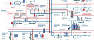
Thermal diagram of a boiler room is intended for a graphical representation of the main and auxiliary equipment, and interconnection using utility networks. Such schemes are mandatory when developing project documentation; they are carried out using elements approved by SNIP.
The diagram shows the flow of coolant through the pipes to the heating devices, boiler, tank and pump. The lines indicate the location of control valves and safety devices.
- 1 What is the difference between basic and detailed thermal circuits?
- 2 What is the difference between closed and open system schemes
- 3 Boiler room diagram when using solid fuel
- 4 Plan with electric boiler
- 5 Scheme with a gas boiler
- 6 Boiler in the boiler room diagram
- 7 Harness with hydraulic arrow
- 8 Diagram of a boiler room with 2 boilers
What is the difference between basic and detailed thermal circuits?
Thermal heat supply schemes can be basic, detailed and installation. The schematic diagram of the boiler room shows only the main thermal power equipment: boilers, heat exchangers, deaeration units, chemical water purification filters, feed, make-up and drainage centrifugal pumps, as well as utility networks that connect all this equipment without specifying the number and location. This graphic document indicates the costs and characteristics of coolants.
The expanded thermal diagram reflects the installed equipment, as well as the pipes with which they are connected, specifying the location of shut-off and control valves and safety devices. In the case when it is impossible to plot all the nodes on a detailed thermal circuit, then it is separated into its component parts according to the technological principle. The boiler room flow diagram provides detailed information on the installed equipment.
What is a contour definition of different meanings
Most often, the word “contour” is used in its geometric meaning, which means the boundary of a flat figure. There are other meanings of this word.
What is an electrical circuit
From an electrical engineering point of view, a circuit is a simple closed circuit consisting of one or more branches connected in series. That is, a closed loop can be called any closed path that passes through the branches of the chain.
What is an information security loop?
CIB - information security loop - is a special software package that is used to control the leakage of corporate information and help detect attempts of unauthorized access to it. This complex was developed in Russia. It operates within the corporation's computer network, controlling its internal information space, as well as a wide range of communication channels.
What is a cartographic contour
In cartography, a contour is a line on a map that connects points of equal height. If the contours are located at a short distance from each other, this means that the slopes of the hill are very steep. Contours at a great distance indicate slightly hilly areas of the earth's surface, and the absence of such contours on the map means that this area is flat.
What is a ground loop
The ground loop is usually installed around the building along the perimeter of the walls. If you look at the ground electrode from above, you will notice that it is mounted along the contour of the object: that is why it is called a ground loop. In fact, it is a group of vertical electrodes that are connected by a horizontal conductor. Such electrodes are mounted near the object at a short distance from each other. The grounding element in such a device is usually either a steel corner or reinforcement (3 meters long). A steel strip measuring 4x40 mm is used as a connecting conductor. It is placed in a pre-prepared ditch half a meter deep. The conductor is connected to the ground electrode using electric or gas welding - gas welding.
What is a DHW circuit?
The DHW circuit is a closed piping system. The main element of such a system is a water-to-water heat exchanger. One of its circuits is used to circulate the heating system coolant (hot water), and the other circuit supplies cold tap water.
Naturally, the concept of “contour” can be found in other sciences, but having a general idea of what a contour is, you can guess their meaning on your own.
What is the difference between closed and open system schemes?
The main difference between an open or gravity heating system and a closed one is the complete absence of devices for forced movement of the coolant through the pipes. This process occurs only due to the thermal expansion of the heated liquid.
Composition of elements in the thermal circuit of a boiler house with an open heat supply circuit:
- The heating source is a hot water boiler operating on solid, liquid and gaseous fuel.
- Expansion tank for thermal compensation of the coolant.
- Temperature compensator overflow pipe.
- Supply (hot) line with heating risers.
- Heating appliances.
- Return line with heating risers.
- Coolant drain valve.
- Heating network feed valve.
The circulation of the heating fluid in a closed boiler installation is carried out thanks to a circulation pump (3), which is installed on the water outlet line from the boiler (1), usually in its upper part, and an air vent (4) is also located here. Water, heating up in the boiler, enters the heating supply pipeline and is directed to the batteries (9) through a thermostatic valve (8).
An expansion tank (7) is installed on the supply line for temperature compensation of water during heating, a safety valve (6) for relieving emergency pressure in the network and a pressure gauge (5) for monitoring the working pressure of the medium.
A Mayevsky valve is installed on the heating device to release the air lock (10). Along the return flow of the coolant, a three-way valve (17), a water purification filter (13), a shut-off valve (15) and a drain valve (14) are installed.
Gas is supplied to the boiler through a gas valve (18) and a filter (19) to purify the energy carrier before the nozzle of the burner device. Make-up water in the water-heating boiler house circuit comes from the water supply system (11) through the valve (16) to the filter to remove suspended solids and hardness salts. The boiler is equipped with a hot water supply line for its own needs (2).
—
CONDITION 1
RESULTS ÑбÑаÑого Ñеплооб¼ÐµÐ½Ð½Ð¸ÐºÐ° плоÑадÑÑ 2 2 м2 ( Ñа registry 0 6 м3, ваÑÐµÐ»Ñ , ASSURANCE. â
RESULTS SYSTEM 2 2 2 ( - 0 6 3, ²Ð°ÑелÑ, ASSURANCE. â
RESULTS ÑбÑаÑого Ñеплооб¼ÐµÐ½Ð½Ð¸ÐºÐ° плоÑадÑÑ 2 2 м2 ( Ñа registry 0 6 м3, ваÑÐµÐ»Ñ , ASSURANCE. â
RESULTS ÑÑ Ð¸Ð· бака-ÑеплообменникР° urn ´Ð¾Ð½Ð°Ð³ÑеваÑеле. › › › registry Ñовод а. â
RESULTS ² Ñом ÑлÑÑае, еÑли ÑеплоноÑиÑели ÑиÑÑÐµÐ¼Ñ Ð¾ÑоР¿Ð»ÐµÐ½Ð ? registry ¾ÑÑи), доп CONTENTS в RESULTS боÑÑ. RESULTS RESULTS RESULTS " оÑнабжениÑ. â
RESULTS, RESEARCH иÑ. $25 ROOM единеннÑÑ Ð±Ð °ÐºÐ¾Ð¼-Ñеплообменником. RESULTS 10 rubles RESEARCH ¸ this ROOM µÐºÑоÑÑ Ð¾Ð±Ñей плоÑадÑÑ 57 6 м2, ÑÑÑбÑаÑÑй Ñеп¿»Ð¾Ð¾Ð±Ð¼Ð µÐ½Ð½Ð¸Ðº Ð 25 June 2, 2019 regurgitation вÐ" RESULTS онÑÑÑе. â
| OPTIONAL CONDITIONS ¬ дома в ÑоÑеÑании Ñ ÑезеÑвнÑми. â |
RESULTS, RESEARCH иÑ. 25. the ÑединеннÑÑ Ð± аком-Ñеплообменником. RESULTS 10 rubles RESEARCH ¸ this ROOM µÐºÑоÑÑ Ð¾Ð±Ñей плоÑадÑÑ 57 6 м2, ÑÑÑбÑаÑÑй Ñеп¿»Ð¾Ð¾Ð±Ð¼Ð µÐ½Ð½Ð¸Ðº Ð 25 June 2, 2019 regurgitation вÐ" RESULTS онÑÑÑе. â
Boiler room diagram when using solid fuel
Solid fuel boilers have a certain disadvantage, which is caused by high inertia of operation, due to the impossibility of fine adjustment of the combustion process of solid fuel.
In order to smooth out the disadvantage, a buffer tank is installed in the circuit, which gains temperature to heat the heating circuit and consumes heat over a long period of time.
This thermal diagram of a solid fuel boiler house consists of:
- Heat supply source with a primary heating circuit: solid fuel boiler;
- safety group with safety valve;
- buffer capacity;
- heating circuit circulation pump;
- boiler circuit circulation pump;
- expansion tank;
- shut-off valves, drains, air vents;
- balancing valve;
- heating circuit mixing unit for automatically maintaining the temperature in the radiators;
- mixing unit of the boiler circuit, for optimal boiler operation;
- weather-compensated or customizable automation with emergency alarm.
Plan with electric boiler
An electric boiler is a unit that heats a coolant by converting electricity into thermal energy. It is used as a heat supply source for small suburban houses or as an emergency source with a gas or solid fuel boiler.
Based on the modification of such devices, various schemes for connecting electric boilers to heating are used. The most popular is a multi-level heating system with a combination of heating devices in the form of radiators and a “warm floor” system.
Basic elements of electric heating for a private house:
- Heating source, electric boiler.
- Safety group, with air vent, safety valve and pressure gauge, to relieve excess pressure in the network.
- Collector for directing water along contours.
- Radiators.
- Heat exchanger for hot water supply.
- Expansion tank for hydraulic compensation of the system.
- Manifold for the "warm floor" system.
- Warm floor system.
- Filter for cleaning coolant from suspended substances.
- Check valve.
- Electric circulation pump.
- Power supply networks.
- Automatic security with alarm.
How does the heating system work in an apartment building?
Due to the high cost of centralized heating, many people increasingly prefer autonomous heating, completely switching to individual heating devices. But many do not realize that an autonomous heating unit in an apartment building is calculated and installed according to the same principle as the installation of a centralized heating main.
- From what date is the heating turned on?
- What is a high-rise building heating system?
- What is return used for?
- Why are batteries often barely warm?
- Purpose of the elevator unit
- The principle of piping the heating main
Scheme with a gas boiler
Gas boilers are the most economical and functional heating sources. The small building essentially houses a mini-boiler room in a private house.
Manufacturers of modern boilers equip the casing with all the necessary equipment in the form of pumps, an expansion tank, a safety relief valve and an air vent. The owner of such equipment only needs to connect the unit to the heating and hot water circuit, which significantly reduces installation costs.
But the main advantage of a comprehensive boiler assembly is the consistency of the operation of all auxiliary components that have been tested and adjusted in the factory.
The simplest thermal diagram of a gas boiler room:
- The source of heat supply is a gas boiler.
- Safety group, with air vent, safety valve, pressure gauge and expansion tank.
- Supply of coolant to heating devices.
- Coolant return from heating devices
- Heating radiators
- Supply of tap water to recharge the heating network with a filter and shut-off safety valves.
- Supply of tap water to the DHW circuit of the boiler.
- Filter for coarse cleaning of coolant from suspended solids on the return line.
- Check valve on the return line.
- Circulation pump on the return line.
Rules for installation on a wall or floor
The gas unit must be placed inside a separate room. which meets the following requirements:
- There is a window that can be opened at any time.
- Availability of functioning ventilation.
- Availability of gas and water pipes.
- The presence of an outlet to ensure the operation of the circulation pump and electronics. Of course, it should be the end of a separate branch that extends from the electrical panel. This cable must be connected to a separate circuit breaker. In addition, grounding is mandatory.
There are also requirements regarding the correct placement of the boiler in the house. They are:
- The distance between the main element of the heating system and other gas appliances must exceed 20 cm.
- There should be no window nearby.
- The distance between the boiler and the socket should be at least 0.5 m (at least, such recommendations are given by manufacturers). In general, the further the outlet is from the boiler, the better. It is worth adding that some models have a power cable without a plug. This means that you need to connect the wire yourself directly to the circuit breaker located in the electrical panel.
- The space between the side walls of the boiler and adjacent walls or objects must be greater than 15 cm.
- The wall on which or near which the boiler is installed must be strong and covered with non-flammable substances. If the wall is such that it can catch fire, it should be covered with at least 3 mm of non-combustible material. This is often noted in various videos.
Boiler in the boiler room diagram
There are various options for connecting an indirect heating boiler to boiler units that can operate on any type of fuel: gas, solid and liquid fuel.
In this scheme with an indirect heating boiler, a water gun or distribution manifold is not installed. The installation of these elements is associated with certain difficulties, as it creates a very complex hydraulic system.
This scheme uses 2 circulation pumps - for heating and domestic hot water. The heating pump runs continuously when the boiler room is running. The DHW circulation pump is started by an electrical signal from the thermostat installed in the tank.
The thermostat detects a drop in the temperature of the liquid in the tank and transmits a signal to turn on the pump, which begins to circulate the coolant along the heating circuit between the unit and the boiler, heating the water to the set temperature.
This scheme is used for all modifications of heating sources installed in both hot water and steam boiler rooms.
A certain modification of the circuit is allowed when a low-power boiler is installed in it. The electric heating pump can be turned off by the same thermostat that turns on the pump to the boiler.
In this option, the heat exchanger heats up faster and the heating is stopped. With prolonged inactivity, the temperature in the room will drop.
In addition, after warming up in the boiler is completed, the pump in the heating circuit comes into operation and begins to pump cold coolant into the boiler, which causes the formation of condensation on the heating surfaces of the boiler and leads to its premature failure.
The process of condensation can also occur in the case of long pipelines laid to the batteries. With a large heat removal from heating devices, the coolant can similarly cool down greatly, and the low return temperature will harm the operation of the boiler.
To protect it from condensation and water hammer that occurs when cold water comes into contact with hot heating surfaces, the system is equipped with a protective circuit equipped with a three-way valve.
The diagram shows a temperature of 55C. The thermostat integrated into the circuit automatically selects the required flow rate to maintain the return coolant temperature.
Radiators for heating systems of high-rise buildings
Cast iron radiators, which have previously been used for decades, are familiar to many residents of multi-storey buildings. If it is necessary to replace such a heating battery, it is dismantled and a similar one is installed, which is required by the heating system in an apartment building. Such radiators for centralized heating systems are considered the best solution, since they can withstand fairly high pressure without problems. The passport for a cast iron battery indicates two numbers: the first of them indicates the operating pressure, and the second indicates the test (pressure) load. Typically these values are 6/15 or 8/15.
The higher the residential building, the greater the operating pressure. In nine-story buildings it reaches 6 atmospheres, so cast iron radiators are suitable for them. But when it is a 22-story building, then for the working functioning of centralized heating systems, 15 atmospheres will be required. In this case, steel or bimetallic heating devices are needed.
Experts do not recommend using aluminum radiators for central heating - they are not able to withstand the operating condition of the water circuit. Also, professionals advise property owners, when carrying out major renovations in apartments and replacing batteries, to change the coolant distribution pipes to ½ or ¾ inches. Usually they are in poor condition and it is advisable to install ecoplast products instead. Some types of radiators (steel and bimetallic) have narrower water flows than cast iron products, so they become clogged and subsequently lose power. Therefore, at the point where the coolant is supplied to the battery, a filter should be installed, which is usually mounted in front of the water meter.
Harness with hydraulic arrow
In complex multi-level heat supply systems, a hydromechanical distributor - a hydraulic switch or a manifold - is often used to balance fluid flows in various sections of the circuit with individual circulation pumps.
A similar scheme of a boiler unit involves turning on an indirect heating boiler through a pump NB and NR, radiator heating through a pump NK1 and NK2, and a warm floor through H1.
It can operate without a hydraulic module; in this case, balancing valves are installed to compensate for pressure drops in various “branches” of the system.
Complete set of thermomechanical equipment:
- Heat supply source – 2.
- Safety group, with air vent, safety valve, pressure gauge and expansion tank.
- Supply of coolant to heating devices.
- Coolant return from heating devices
- Heating radiators.
- Warm floor system.
- Indirect heating boiler
- Filter for coarse cleaning of boiler water from suspended solids on the return line.
- Check valve on the return line.
- Circulation pumps: through the main pipeline, in the underfloor heating circuit and indirect heating boiler.
Boiler room diagram with 2 boilers
The use of two gas units for one heating system is a fairly popular solution among owners of autonomous heating systems with a system thermal power above 50 kW.
This may be a large heated area of the facility, or the presence of additional heat loads in the form of hot water or air-heated heating units.
The use of two units per thermal circuit has a number of advantages compared to one source of equivalent power. First of all, because several small-sized units of less weight are much easier and more economical to place in a boiler room, which is especially important when constructing roof-mounted or semi-basement furnaces.
In addition, the installation of 2 units significantly increases the operational reliability of the heat supply system. In the event of an emergency stop of one of the units, it will continue to function with 50% thermal load.
This piping scheme significantly increases the working life of boilers, due to the fact that they are less loaded during the heating period of the year.
What does the heating control system calculate?
Modern control systems calculate the required water temperature in the boiler (flow temperature) depending on the outside temperature. The relationship between the outside temperature and the flow temperature is shown on the graph as a heating curve. The lower the outside temperature, the higher the supply line temperature should be. There are three types of regulation of the heating system:
settings:
- regulation based on outside temperature
- room temperature regulation
- regulation based on outside temperature, taking into account factors influencing indoor temperature
Illustration No. 2 Graphic characteristic of the heating circuit (example) X - Outside temperature Y - Flow temperature

