Closed expansion tanks and hydraulic accumulators have approximately the same design: a durable metal shell, divided inside by a rubber membrane into two sections.
One section contains water, the other contains air. As water pressure increases, the air is compressed, the size of the section with air decreases, and the membrane bends, water displaces the air. The device has a connection to the water supply system on one side, and a spool valve for pumping air on the other.
But devices are named not because of their design features, but according to their intended purpose.
Purpose
- Expansion tanks are designed to compensate for the expansion of water due to heating in heating circuits, as well as hot water supply (DHW).
- Hydraulic accumulators are designed to accumulate volumes of water under pressure in water supply systems that have a pressure pump, to reduce the frequency of switching on of this pump and to smooth out water hammer. An additional function is a supply of food-grade water up to 1/3 of the total tank volume.
The nuance is that the same device is used for both hot and cold water supply, but it can be called differently, depending on what it does in a particular circuit - it either accumulates (accumulates) a supply of water, or takes its excess during thermal expansion.
- The design feature of the hydraulic accumulator is often that inside there is not a membrane, but a bulb made of food-grade rubber, which is pumped with water. Water does not come into contact with the tank body.
- The expansion tank for the heating system is made of a membrane made of technical rubber, which divides the housing into two compartments, and the coolant (not always water) is in direct contact with the housing.
How to differentiate
In appearance, all membrane tanks are similar to each other. There is an opinion that for the heating system - red, and for water supply - blue. But it is not entirely true, since some manufacturers use other colors.
In fact, devices can be distinguished from each other only by technical characteristics, which are indicated on the nameplates on the devices themselves:
- All devices for water supply, including for hot water supply - low temperature - up to 80 degrees C, but high pressure - up to 12 Atm;
- expansion tanks for heating - high temperature - up to 120 degrees C, but low pressure up to 4 Atm.
How water storage schemes work
The hydraulic accumulator in the water supply circuit smoothes out pressure surges that occur when water is drawn from the system, i.e. when opening the tap, and reduce the number of pump starts, which should not be more than 50 times per hour.
When water is taken in the volume of a cup, the hydraulic accumulator will release this volume, the pressure in the system will drop, but not so much that the pressure switch turns on the pump. When taking a larger volume (for example, the volume of a bucket), the pressure will drop so much that the pump will turn on and fill the device. The expansion tank in hot water supply and heating systems receives the excess volume of water that arises when it is heated.
If there were no such device, then in a heating closed circuit the pressure would very quickly rise above the critical one, since the liquid is practically not compressed. This would result in the release of water from the emergency pressure valve, which is usually set to a pressure of 3 atm.
Types of hydraulic water tanks, divided by location and other parameters
Let's present this section in tabular form for ease of understanding:
| Separation | Designation | Peculiarities |
| Location type | Horizontal | The volume of such tanks is larger. The vertical position allows the air release valve to be installed from above. This makes maintenance easier. The only limitation in installation is the volume of the room. |
| Vertical | Compact options in which a tap is installed to vent air. The disadvantage is that in some models you have to completely drain the water to bleed the air, which is not economical. | |
| Energy storage | Pneumatic accumulation | Diaphragm, balloon or piston. The problem arises when the partition wears out - expensive and labor-intensive repairs are required. |
| Balloon or pear | Most popular. When worn out, the pear is replaced with a new one independently, without the involvement of professionals. | |
| Mechanical storage | Weight or spring. Work is based on kinetic energy. Quite voluminous and work autonomously. |
How to choose tank volume
You can choose the tank volume arbitrarily. There are no requirements or restrictions. The larger the volume of the tank, the greater the supply of water you will have in case of a shutdown and the less often the pump will turn on.
When choosing a volume, it is worth remembering that the volume that appears in the passport is the size of the entire container. There will be almost half as much water in it. The second thing to keep in mind is the overall dimensions of the container. A 100 liter tank is a decent-sized barrel - about 850 mm high and 450 mm in diameter. You will need to find a place somewhere for it and the harness. Somewhere - this is in the room where the pipe from the pump comes. This is where all the equipment is usually installed.
If you need at least some guidelines to select the volume of a hydraulic accumulator, calculate the average flow rate from each water intake point (there are special tables or you can look at the data sheet for household appliances). Sum up all this data. Get the possible consumption if all consumers work simultaneously. Then figure out how many and which devices can work at the same time, calculate how much water will be consumed in a minute in this case. Most likely by this time you will have already come to some decision.
Connecting the accumulator to the system
Typically, the water supply system of a private home consists of:
This scheme may also include a pressure gauge for operational pressure control, but this device is not necessary. It can be connected periodically to carry out test measurements.
With or without five-pin fitting
If the pump is of a surface type, the hydraulic accumulator is usually placed next to it. In this case, the check valve is installed on the suction pipeline, and all other devices are installed in one bundle. They are usually connected using a five-pin fitting.
It has terminals with different diameters, just for the devices used for tying the hydraulic accumulator. That’s why the system is most often assembled on its basis. But this element is not at all necessary and everything can be connected using ordinary fittings and pieces of pipe, but this is a more labor-intensive task, and there will be more connections.
How to connect a hydraulic accumulator to a well - diagram without a five-pin fitting
With one inch outlet, the fitting is screwed onto the tank - the pipe is located at the bottom. A pressure switch and pressure gauge are connected to the 1/4 inch outlets. The remaining free inch terminals are connected to the pipe from the pump and wiring to consumers. That's all for connecting the gyroaccumulator to the pump. If you are assembling a water supply circuit with a surface pump, you can use a flexible hose in a metal winding (with inch fittings) - it is easier to work with.
A visual diagram of connecting the pump and accumulator - use hoses or pipes where necessary
As usual, there are several options, the choice is yours.
The hydraulic accumulator is connected to the submersible pump in the same way. The whole difference is where the pump is installed and where the power is supplied, but this has nothing to do with the installation of the accumulator. It is placed in the place where the pipes from the pump enter. Connection is one to one (see diagram).
How to install two hydraulic tanks on one pump
When operating the system, sometimes owners come to the conclusion that the available volume of the accumulator is not enough for them. In this case, you can install a second (third, fourth, etc.) hydraulic tank of any volume in parallel.
There is no need to reconfigure the system; the relay will monitor the pressure in the tank on which it is installed, and the viability of such a system is much higher. After all, if the first accumulator is damaged, the second one will work. There is another positive point - two tanks of 50 liters each cost less than one of 100. The point is that the technology for producing large-sized containers is more complex. So it is also more economical.
How to connect a second accumulator to the system? Screw a tee onto the input of the first one, connect the input from the pump (five-pin fitting) to one free output, and connect the second container to the remaining free one. All. You can test the circuit.
Selection of hydraulic accumulator
The volume of the selected accumulator tank must be greater than or equal to the volume obtained as a result of the calculation. There are no negative consequences from overestimating the volume of the hydraulic accumulator beyond the calculated value, no matter how much it is exceeded.
When selecting a hydraulic accumulator, you should take into account its temperature and strength characteristics. The maximum pressure of the tank must be greater than or equal to the maximum pressure at its connection point.
If the installation of hydraulic accumulators is planned indoors, then it should be taken into account that tanks with a diameter of more than 750 mm and a height of more than 1.5 m may not fit through the doorway, and mechanization will be required to move them. In this case, it is better to give preference to not one, but several hydraulic accumulator tanks of smaller capacity.
When choosing a hydraulic accumulator, you should remember that the volume of water stored in it is on average 40-50% of the tank volume.
Tank volume is the main selection criterion
The most important question is how to choose the volume of a hydraulic accumulator for water supply systems. To answer it, you need to bring together a lot of data. This includes the performance of the pump, the equipment of the house with water-consuming equipment, the number of people permanently living in the house, and much more.
But first of all, you need to decide whether you need this reservoir only to stabilize the operation of the system as a whole, or whether there is a need for a supply of water in case of a power outage.
Internal cylinders of different volumes
If the house is small and equipped only with a washbasin, toilet, shower and watering tap, and you do not live in it all the time, you don’t have to make complex calculations. It is enough to buy a tank with a volume of 24-50 liters, it will be enough for the system to work normally and be protected from water hammer.
In the case of a country house for permanent family residence, equipped with everything necessary for a comfortable life, it is advisable to approach the issue more responsibly. Here are a few ways you can decide on the size of your accumulator.
According to pump characteristics
The parameters that influence the choice of tank volume are the performance and power of the pump, as well as the recommended number of on/off cycles.
- The higher the power of the unit, the larger the volume of the hydraulic tank should be.
- The powerful pump pumps water quickly and turns off quickly if the tank volume is small.
- A sufficient volume will reduce the number of intermittent starts, thereby extending the service life of the electric motor.
To calculate, you will need to determine the approximate water consumption per hour. To do this, a table is compiled that lists all devices that consume water, their quantity and consumption rates. For example:
Table for determining the maximum water flow
Since it is almost impossible to use all devices at the same time, a correction factor of 0.5 is used to determine the actual flow rate. As a result, we get that you spend an average of 75 liters of water per minute.
How to calculate the volume of a hydraulic accumulator for water supply, knowing this figure, the performance of the pump and taking into account that it should turn on no more than 30 times per hour?
- Let's say the productivity is 80 l/min or 4800 l/h.
- And during peak hours you need 4500 l/h.
- When the pump operates non-stop, its power is quite sufficient, but it is unlikely to work for a long time in such extreme conditions. And if it turns on more than 20-30 times per hour, then its resource will run out even faster.
- That’s why we need a hydraulic tank, the volume of which will allow us to turn off the equipment and give it a break. At the indicated cycle frequency, the water supply should be at least 70-80 liters. This will allow the pump to remain idle for one minute out of every two, pre-filling the reservoir.
According to the formula of the minimum recommended volume
To use this formula, you need to know the settings of the pressure switch, which turns the pump on and off. The following picture will help you understand:
Changes in pressure in the accumulator when turning the pump on and off
- 1 – initial pressure Pair (with the pump turned off);
- 2 – water flow into the tank when the pump is turned on;
- 3 – reaching the maximum pressure Pmax and turning off the pump;
- 4 – water flow with the pump turned off. When the pressure reaches the minimum Pmin, the pump turns on.
The formula looks like this:
- V = K x A x ((Pmax+1) x (Pmin +1)) / (Pmax - Pmin) x (Pair + 1), where
- A is the estimated water flow (l/min);
- K – correction factor from the table, determined depending on the pump power.
Table for determining the correction factor
You must set the values of the minimum (starting) and maximum (switching off) pressure on the relay yourself, depending on what pressure you need in the system. It is determined by the farthest and highest water collection point from the accumulator.
Approximate ratios of pressure switch settings
To adjust the pressure switch, you need to know how to inflate a hydraulic accumulator for water supply systems with air, or bleed off excess air. To do this, you will need a car pump, which is connected to the tank through a spool.
Now you can calculate the volume. For example, let's take:
- A = 75 l/min;
- Pump power 1.5 kW, respectively K = 0.25;
- Pmax = 4.0 bar;
- Pmin = 2.5 bar;
- Pair. = 2.3 bar.
We get V = 66.3 liters. The nearest standard hydraulic accumulators in terms of volume have a volume of 60 and 80 liters. We choose the one that is larger.
This is interesting: How to choose a wood splitter (video)
What should the air pressure be in the air cavity of the hydraulic tank?
Many people don’t think about it, or simply don’t know that they need to keep an eye on this. Unfortunately, yes, it is necessary; the service life of the hydraulic tank membrane, and ultimately the pump, directly depends on this.
We measure the air pressure in the air cavity of the hydraulic tank. We do this only with the hydraulic tank disconnected from the system.
— turn off the power to the pump, open any tap behind the pump and wait until the water comes out of the hydraulic tank.
Or we measure it on an installation that is not yet connected to the water supply system. To do this, remove the decorative cap from the air nipple of the hydraulic tank and connect a regular car pressure gauge to it (to check the pressure in the car tires). Let's remember this pressure. (As a rule, on small hydraulic tanks with a capacity of up to 50 liters, this pressure will be 1.5 bar). Now the most important rule : the air pressure in the hydraulic tank should be less than the pump activation pressure by about 10%
. Those. if the pump activation pressure is 1.6 bar, then the air pressure should be 1.4-1.5 bar. In most cases, these are the factory settings mentioned above. Those. By purchasing a ready-made pumping station, you already have a fully configured system. But once you have made changes to the factory settings of the pressure switch, you must always change the air pressure in the hydraulic tank. For example, if you set P on = 2.5 bar, P off = 3.5 bar, then it is necessary to raise the air pressure to a value of 2.2-2.3 bar.
By the way, even if you haven’t changed anything in the factory settings, you need to regularly monitor the air pressure, or at least check it once a year at the beginning of the summer season. It is important that this pressure be constant, but if it has dropped a little over the winter, it can always be raised with a regular car pump to the required level.
All these simple operations will not take much time; it is enough to pay attention to them once a year, especially since everything will pay off in the long and uninterrupted operation of the entire water supply system as a whole.
2007 website Setting the pressure switch and adjusting the air pressure in the accumulator.
To prevent the pump from turning on every time a faucet is opened in the house, a hydraulic accumulator is installed in the system. It contains a certain volume of water, sufficient for a small flow rate. This allows you to practically get rid of short-term pump starts. Installing a hydraulic accumulator is not difficult, but you will need a few more devices - at least a pressure switch, and it is also desirable to have a pressure gauge and an air vent.
Principle of operation
The storage tank begins to accumulate excess heat in the upper part of the tank after the room is completely heated. As the accumulator cools, it gradually releases heat into the heating system.
The capacity of the hydraulic accumulator determines how many times during the day the solid fuel boiler will be loaded.
The operation of the storage tank is based on the use of high heat capacity of water, which, when cooled by 1 °C, releases several times more heat to heat 1 m2 of room.
To calculate the volume of the storage tank, use the ratio - 25 - 30 liters of tank per 1 kW of solid fuel boiler power.
For example, for a 20 kW boiler, the tank volume will be from 500 to 600 liters.
Verification methods
To check the pressure, you can use a car pressure gauge
. The air pumped into the container at the factory gradually escapes through the rubber membrane and nipple. Rarefaction of the gas cavity leads to excessive stretching of the rubber bulb when filling it with liquid. Without resistance, the membrane wears out quickly and may burst. Air pressure is measured with a pressure gauge. The best option is a car measuring device.
The manufacturer's instructions indicate the number of checks for the device model. The average is 2 times a year. Before starting the parameter measurement procedure, all liquid must be drained from the tank. The pump is disconnected from the power supply system. The tank must be empty at the time of measurements. Control is required before connecting the device to the system. During storage in a warehouse, some air may leak out of the tank. The operating pressure is indicated in the product data sheet.
To check, unscrew the decorative cap covering the nipple. The node is located in the upper part of the housing. A pressure gauge is connected to the spool. The device must have a minimum error. Electronic and automotive devices are recommended. It is better not to use cheap plastic pressure gauges; they have a significant error in their readings. If the level is below the factory parameters, air is pumped in using a compressor. The hydraulic accumulator is left for a day for monitoring. After the next measurement that meets the standard, the device is installed. Exceeding the optimal pressure is eliminated by bleeding the air.
The number of checks depends on how long the plumbing system has been in use. For summer cottages where communications are operated in the spring and summer, indicators are monitored before the start of the season. A sign of a decrease in air pressure is the frequent turning on and off of the pump. In case of any deviations from the norm, an unscheduled inspection is carried out. Minor air loss can be pumped up with a car pump.
Why do you need a hydraulic accumulator in a heating system, how to choose and configure it
The hydraulic accumulator is an integral component for autonomous plumbing and heating systems.
Without this device, it is difficult to ensure an uninterrupted supply of liquid from wells and boreholes.
Therefore, these mechanisms are very popular among summer residents and owners of private houses; this unit often comes complete with a pump, but it can be purchased and installed separately.
articles:
The installation is most often used for water supply needs.
But no less relevant is the use of a hydraulic accumulator for heating systems (how to remove an airlock).
This mechanism serves to absorb the excess volume of liquid substance and, thereby, reduce excess pressure in the line, and, if necessary, return water back into the system to maintain optimal pressure of the working medium.
In fact, there are three goals, and they are all interconnected:
- The ability to accumulate the volume of liquid necessary for normal operation of the heating system.
- Accumulating water, requisition excess pressure.
- Suppression of water hammer in the heating system (how to bleed air through a Mayevsky tap is written here). It is for this reason that even the smallest devices have quite large threads.
Thanks to the design capabilities of the hydraulic accumulator (expansion tank), it is possible, in automatic mode, to normalize the coolant pressure values in case of temperature changes.
What do you know about a water seal for sewerage? This useful article describes the types of dry and water devices to prevent the penetration of unpleasant odors into rooms where plumbing equipment is located.
Read what electrodes you need to buy for welding aluminum with an inverter on this page.
The procedure for setting pressure - what it should be and how to set it
The coolant pressure in the heating system tank is an adjustable parameter. You can perform all setup steps yourself.
To do this you need:
- Make calculations and understand what pressure should be in the expansion tank. It should be made 0.2 atmospheres less than in the heating system.
- This indicator is set before placing the container by releasing air or pumping it in through a nipple. But first you need to know how to pump up the heating expansion tank correctly.
- The container is connected to the pipeline and the system is filled with water, doing it slowly, observing the pressure indicators. The liquid is pumped until the pressure levels are equal.
- Then connect the pump and continue to pump liquid until the pressure in the tank reaches the operating values, which are calculated before installing the network. As a result, a reserve volume of coolant will enter the housing.
- The system must be started at maximum temperature, and then the volume of the working medium increases by the specific increment. This ensures that water enters the device, the volume of which is equal to the capacity of the tank. As a result, the pressure reaches maximum values.
To know what the pressure should be in the expansion tank of a double-circuit boiler, you should look at the instructions for it. You can set all parameters yourself using a pressure gauge and a car compressor.
Role in the heating system
The main tasks of the hydraulic accumulator:
- accumulation of “excess” coolant during its expansion;
- air removal;
- replenishment of volume in case of possible leaks or drop in water (antifreeze) level.
There are two types of tanks - open and closed type. The second option is used in most modern heating systems. This is a completely sealed hydraulic accumulator with a membrane or bulb (it is used in large containers).
Hydraulic accumulators are installed only for heating with a circulation pump, since this system is characterized by high operating pressure.
Design and principle of operation
The battery has a cylindrical, oval or spherical shape. It is most often made of steel coated with powder paint.
Inside the cylinder there is a rubber chamber in the shape of a membrane or pear - this is the main element of equipment that allows you to regulate the pressure. Devices with a flat rubber chamber are also called a membrane tank.
When expanding, water enters the tank, expanding the rubber chamber. And when it cools, the membrane or bulb returns to its original position - the coolant is pushed back into the system.
The air chamber is filled with air, and the pressure in this compartment is set by the manufacturer and allows the chamber (membrane or bulb) to be returned to its original position. Factory settings are 1.5 atmospheres.
The price of such equipment is quite affordable for owners. For example, a container of 18 liters costs from 960 rubles.
The volume determines not only the cost, but also the suitability of the accumulator for a specific heating system. Therefore, before purchasing, the necessary calculations are made to determine the capacity of the tank and ensure proper operation of the system.
A closed tank allows you to compensate for any pressure drop if its volume has been selected correctly - in accordance with the system parameters.
Installation diagram of a hydraulic accumulator to a submersible pump
The hydraulic tank connection diagram is similar to the previous one, the difference lies in the method of installing the pump.
The water supply system from a submersible pump uses a check valve that prevents water from leaving the membrane back into the hydraulic structure. The valve is mounted in front of the supply pipe on the pumping equipment; in some cases, an internal thread is made on the cover for this purpose.
For connection, a fitting of the required diameter with an external thread is used. After installing the valve, a supply water pipe of the required length is connected to it.
The length is determined quite simply: the end of the rope with a sinker is lowered into the hydraulic structure and the top point of the structure is marked. Next, the rope is raised and the length is measured from the sinker to the top point. The height from the point to the place where the pipe from the hydraulic structure is laid into the ground, as well as the length of the pumping equipment with the valve, is subtracted from the finished value. The optimal pipe length is when the equipment rises above the bottom of the well or well to a height of up to 35 cm.
Next, installation and adjustment of the hydraulic accumulator is carried out according to the standard scheme.
Connecting the hydraulic tank
Characteristics of water pressure switch for pumps
A hydraulic tank is the second name for a hydraulic accumulator. It can be connected to the water supply system in various ways. The choice of a suitable connection scheme mainly depends on the capacity in which the device will be used, as well as what tasks it will perform. It is worth considering several of the most popular connection methods.
Using a surface pump
It is worth examining step by step how the hydraulic accumulator is connected to the system if there is a surface pump subtype.
- First you need to check the air pressure in the inside of the tank. It should be 0.2-1 bar less than the parameter on the relay.
- Then you should prepare the equipment for connection. In this situation, the equipment means: a fitting, a pressure gauge, a tow with a sealing compound, a relay responsible for pressure.
- You need to connect the fitting to the tank. The connection area can be a hose or a flange with a bypass valve.
- Then you should screw on the other devices one by one.
To determine the absence of leaks, you need to run the equipment in test order
When connecting the relay, which is responsible for regulating the pressure, it is important to inspect all the marks. Under the cover there are contact connections - “network” and “pump”
Do not confuse the wires. If there are no marks under the relay cover, then it is better to contact a professional to connect it to avoid a serious mistake.
With submersible pump
The submersible or deep-well type of pump differs from the above option in that it is located in a well or dug well, in other words, in the area from which water is sent to the home, and in the above situation, to the hydraulic accumulator. One detail is very important here - the check valve. This element is designed to protect the system from liquid penetration back into the well or well. This valve is fixed on the pump next to the pipe. For this purpose, a thread is cut in its lid.
First of all, fix the check valve, and then connect the hydraulic accumulator itself to the system.
The diagram is as follows:
- to measure the length of the pipe running from the deep-well pump to the extreme point of the well, you basically take a string with a weight;
- the load is lowered to the bottom, and a mark is made on the rope to mark the edge of the well at the top;
- after removing the rope, you can calculate the length of the pipe from the lowest plane to the top;
- you need to subtract the length of the well, as well as the distance from the section where the pipe passes into the soil to the highest level of the well;
- In addition, it is very important to take into account the immediate location of the pump (pump) - it should be located 20–30 cm from the bottom.
Construction of hydraulic accumulators for water supply to private houses
This unit consists of two parts - the hydraulic tank itself and a membrane that divides its internal volume into 2 sections, one of which is filled with water and the other with air. Hydraulic tanks of 100 liters or more are equipped with a valve through which air accumulated in the water is released. Smaller devices are equipped with a special valve or tap for these purposes.
The membrane for the hydraulic accumulator is made of butyl - a special rubberized material that is resistant to bacterial influences and meets all the requirements of sanitary and epidemiological standards.
Sometimes the bulb inside the tank bursts - in this case replacement is required
What should be the pressure in the accumulator?
One part of the accumulator contains compressed air, and water is pumped into the second. The air in the tank is under pressure - factory settings - 1.5 atm. This pressure does not depend on the volume - it is the same on a tank with a capacity of 24 liters and 150 liters. The maximum permissible maximum pressure may be more or less, but it does not depend on the volume, but on the membrane and is indicated in the technical specifications.
Preliminary check and pressure correction
Before connecting the accumulator to the system, it is advisable to check the pressure in it. The settings of the pressure switch depend on this indicator, and during transportation and storage the pressure could drop, so monitoring is very desirable. You can control the pressure in the hover tank using a pressure gauge connected to a special input in the upper part of the tank (capacity of 100 liters or more) or installed in its lower part as one of the piping parts. Temporarily, for control, you can connect a car pressure gauge. Its error is usually small and it is convenient to work with. If this is not the case, you can use the standard one for water pipes, but they are usually not very accurate.
If necessary, the pressure in the accumulator can be increased or decreased. There is a nipple at the top of the tank for this purpose. A car or bicycle pump is connected through the nipple and the pressure is increased if necessary. If it needs to be vented, the nipple valve is bent with some thin object, releasing the air.
What air pressure should be
So should the pressure in the accumulator be the same? For normal operation of household appliances, a pressure of 1.4-2.8 atm is required. To prevent the tank membrane from tearing, the pressure in the system should be slightly higher than the pressure of the tank - by 0.1-0.2 atm. If the pressure in the tank is 1.5 atm, then the pressure in the system should not be lower than 1.6 atm. This value is set on the water pressure switch, which works in tandem with the hydraulic accumulator. These are the optimal settings for a small one-story house.
If the house is two-story, you will have to increase the pressure. There is a formula for calculating the pressure in the hydraulic tank:
Vatm.=(Hmax+6)/10
Where Hmax is the height of the highest point of water intake. Most often this is a shower. You measure (calculate) at what height relative to the hydraulic accumulator its watering can is located, substitute it into the formula, and get the pressure that should be in the tank.
If the house has a jacuzzi, everything is more complicated. You will have to select it empirically - changing the relay settings and observing the operation of water points and household appliances. But at the same time, the operating pressure should not be greater than the maximum permissible for other household appliances and plumbing fixtures (indicated in the technical specifications).
Hydraulic accumulator device, principles of operation
Water pressure switch for pump
To better understand the functions of individual elements, it is necessary to consider the system as a whole.
From a well or other source, water is pumped into the main pipeline. To prevent it from moving in the opposite direction, a safety valve is installed. Shut-off valves are installed in the required places. It is used for preventive maintenance, adjustments, and replacement of failed units.
Water flows through the pipeline into a special container, which performs several functions:
The main working element of such a container is a flexible partition. But the initial pressure in the tank itself is created by the pump. With appropriate equipment, it is controlled from a special remote control. Data is received there from the pressure switch for the hydraulic accumulator.
Above is part of a smart home class diagram. It connects to the general control system. In practice, more economical solutions are often used.
To successfully solve the identified problems, the following designs of hydraulic accumulators are used:
This picture shows another important element, the flow filter. It prevents the entry of mechanical contaminants, damage to the relay and blocking of its drive mechanisms. The increased tank capacity is useful not only for high daily consumption. It will reduce the number of pump starts/stops, which will have a positive impact on the durability and reliability of the system.
The standard method for calculating tank volume (VT) uses the following formula:
OB=16.5 x RV/KV x CD x 1/DVK, where:
In order not to embarrass oneself when living year-round, a tank with a capacity of 40-60 liters is sufficient for a family of three. Similar advice is given by specialized experts. In fact, it is better to make a more accurate calculation using the above method. The results obtained should be increased taking into account guest visits and other situations accompanied by increased water consumption. This approach will help you purchase a hydraulic accumulator for water supply, the price of which will correspond to the technical characteristics and needs of future users.
When placing the tank at the highest point of the structure, the force of gravity will be used. But we must take into account that the room must be reliably protected from adverse external influences. It maintains temperatures above 0°C all year round.
It is necessary to remember about the increase in mechanical loads. A large water tank weighs a lot, so sometimes additional reinforcement of the structure’s load-bearing frame is required. For these reasons, large containers are often installed in the basement.
Related article:
How to install a pressure switch for a hydraulic accumulator
Before performing work operations, it is necessary to clarify the general requirements. In order for the water supply system to function optimally, the pressure difference for turning the pump on and off is set within the range from 0.9 to 1.8 atm. Exceeding it will increase energy consumption.
To calculate what pressure should be in the hydraulic accumulator (DHA), use the formula DHA = (B+6.5)/10, where:
The process of connecting a pressure switch to a hydraulic accumulator
For study, this article discusses a mechanical pressure switch for a hydraulic accumulator. This design is repeated in modifications by different manufacturers, with relatively minor changes.
This product is connected to the water supply system in assembled form. Flexible tubing designed for appropriate pressure levels can be used to place it in a convenient location. If necessary, use transition fittings. Upon completion of installation, the tightness of the threaded connections is checked experimentally.
The electrical connection can be made directly to the pump power supply circuit. Use wires designed for appropriate power. To eliminate errors, it is recommended to use products with color braiding. The “earth” standard is a combination of yellow and green. The electric motor is connected to a 220 V network through an automatic device, which ensures quick shutdown in the event of a short circuit.
All electrical installation work is carried out with the voltage turned off. It is necessary to exclude accidental supply of voltage during the process of adjusting the pressure switch for the hydraulic accumulator.
What is a hydraulic accumulator
A hydraulic water tank is a special sealed metal device with an internal elastic membrane, designed to maintain a constantly stable pressure in the water supply.
In addition, the device is used to solve the following problems:
- Protecting pumping equipment from wear. The pump will turn on when the water tap is opened if the accumulator tank is completely empty. This will result in more unused pump starts and longer pump life.
- Maintaining constant pressure in the water supply system, preventing pressure drops and water hammer while simultaneously using several water intake points.
- Maintaining an optimal supply of liquid in the water supply system, which ensures water supply in conditions of frequent power outages.
This is interesting: Garage made from a profile pipe: what is important to know
Video description
What the pressure should be, see the video:
Optimizing underpressure
The problem of excess pressure also occurs, but quite rarely. Most often it is not enough, and this issue is solved in several ways. Here are the two most popular.
With booster pump
A booster pump is included in the system. That is, this pump is not present to supply water, but to forcibly increase its pressure. This solution can be considered optimal when there is water in the source, but due to its distance from the distribution points, it loses pressure along the way.
Scheme with booster pumps Source ppt-online.org
It is ideal when such a pump is controlled automatically, which itself starts and stops its operation when necessary. This option is suitable for both private houses and apartments, but in the latter case there is a risk of leaving neighbors without water.
Using a storage tank
If there is not enough water in the well (the flow rate of the source is reduced), installing a booster pump will not only not solve the problem, but will also aggravate it. In this case, a sufficiently large storage tank must be installed in front of this pump, and in the absence of water intake, water will be pumped into it.
In this case, the owner himself will decide what pressure is in the accumulator, because this is not important. If such a tank is equipped with a float sensor, it will itself give the pump a command to turn on when the water in the tank is used up to a certain limit.
System with large storage capacity Source seid-nn.ru
If you place the container in the attic, it will also be filled by means of a pump, but it will flow to the flow points by gravity. True, the pressure will not be strong enough, and most likely, you will have to install another pump that will supply water from the tank. By using the second pump, you can place the barrel anywhere – even in the basement.
Installation of a heating accumulator
The expansion tank should only be installed in a heated room. If the weight of the hydraulic accumulator exceeds 30 kilograms, then it is installed on a special stand. The location for the expander must be easily accessible for maintenance.
Heating and water supply systems
The insertion is made into the pipes only on the return line. The insertion is made between the final radiator, close to the boiler. A check valve and a pressure gauge are installed in front of the expansion tank to constantly measure the pressure in the system.
It is best to choose a model with a replaceable membrane, which can be replaced if broken without much effort. If possible and desired, the hydraulic accumulator can be installed without outside help, but if you are not sure or don’t want to tinker for a long time, you can hire a specialist. However, in this case you will not be able to save money.
Thermal storage in a solar heating system
The need to improve the heating system of their own home forces owners to constantly search for useful ideas, additional devices that allow them to save fuel, distribute heat evenly inside the house, and increase the heat output of radiators.
The problem of uniform heat distribution is especially acute in houses with solid fuel boilers. In them, it is impossible to instantly stop the process of fuel combustion and the supply of heat to the system pipeline. If you turn off the supply tap, hot water accumulating at the inlet can reach the boiling point and damage part of the pipeline. You can distribute the amount of kindling over time. Such solutions are labor-intensive and ineffective. In this case, it is advisable to use a heat accumulator, which will ensure uniform distribution of heat throughout the house and eliminate temperature changes.
In houses with a built-in heat accumulator, heat loss is significantly reduced.
A hydraulic accumulator is a container that accumulates the heat produced by a solid fuel boiler, preserving it for a long time. The device works on the principle of a thermos.
The storage tank consists of the following components:
- Large container made of steel or stainless steel (rectangular or round);
- Four pipes inside the container, spaced apart in height. One is the outlet from the heater to the tank, and the other is the inlet of the heating system, the same in the lower part;
- A safety valve is built into the hydraulic accumulator at the top;
- The outside of the container is insulated with a thick layer of insulating material.
The buffer tank accumulates the heated coolant inside and maintains heat in the house for up to two days after the heating system is turned off.
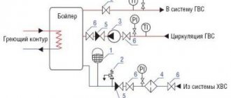
When installing a hydraulic accumulator, it is necessary to arrange a piping circuit between it and the boiler, including:
- Circulation pump;
- Thermal displacement valve;
- Expansion tank.
The storage tank must be thermally insulated, otherwise the generated heat will heat the room where the accumulator is located.
The storage tank works like this:
- From the solid fuel boiler, heated water flows to the upper pipe;
- The circulation pump, while working, expels cold water from the bottom of the heat accumulator into the solid fuel boiler until the entire tank is filled with hot water;
- The next step is to supply hot water from the battery tank to the heating system. Using a circulation pump, cooled water is transferred from the heating system to the tank, and from the tank to the system.
Functions, purpose, types
Installation location - in a pit or in a house.
In the water supply system of a private house without a hydraulic accumulator, the pump turns on every time water flows somewhere. These frequent starts lead to wear and tear on the equipment. And not only the pump, but the entire system as a whole. After all, every time there is an abrupt increase in pressure, and this is a water hammer. To reduce the number of pump starts and smooth out water hammer, a hydraulic accumulator is used. The same device is called an expansion or membrane tank, a hydraulic tank.
Purpose
We found out that one of the functions of hydraulic accumulators is to smooth out water hammer. But there are others:
- Reducing the number of pump starts. There is some water in the tank. With a small flow rate - wash your hands, wash yourself - water flows from the tank, the pump does not turn on. It will turn on only when there is very little left.
- Maintaining stable pressure. This function requires one more element - a water pressure switch, but they maintain the pressure within the required limits.
- Create a small supply of water in case of power outage.
Installing a hydraulic accumulator in a pit
It is not surprising that most private water supply systems have this device - there are many advantages from its use.
Kinds
The hydraulic accumulator is a tank made of sheet metal divided into two parts by an elastic membrane. There are two types of membrane - diaphragm and balloon (bulb). The diaphragm is attached across the tank, a pear-shaped cylinder is secured at the inlet around the inlet pipe.
According to their purpose, they are of three types:
- for cold water;
- for hot water;
- for heating systems.
Hydraulic tanks for heating are painted red, tanks for water supply are painted blue. Expansion tanks for heating are usually smaller in size and lower in price. This is due to the membrane material - for water supply it must be neutral, because the water in the pipeline is potable.
Two types of hydraulic accumulators
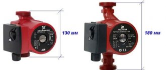
Depending on the type of arrangement, hydraulic accumulators can be horizontal or vertical. Vertical ones are equipped with legs; some models have plates for hanging on the wall. It is the elongated upward models that are most often used when independently creating water supply systems for a private home - they take up less space. The connection of a hydraulic accumulator of this type is standard - through a 1-inch outlet.
Horizontal models are usually equipped with pumping stations with surface-type pumps. Then the pump is placed on top of the tank. It turns out compact.
Principle of operation
Radial membranes (in the form of a plate) are used mainly in gyroaccumulators for heating systems. For water supply, a rubber bulb is usually installed inside. How does such a system work? As long as there is only air inside, the pressure inside is standard - the one that was set at the factory (1.5 atm) or that you set yourself. The pump turns on, begins to pump water into the tank, and the pear begins to increase in size. Water gradually fills an increasingly larger volume, increasingly compressing the air that is located between the wall of the tank and the membrane. When a certain pressure is reached (usually for one-story houses it is 2.8 - 3 atm), the pump is turned off, and the pressure in the system stabilizes. When you open a tap or other water flow, it comes from the accumulator. It flows until the pressure in the tank drops below a certain level (usually about 1.6-1.8 atm). After which the pump turns on, the cycle repeats again.
The operating principle of a gyroaccumulator with a pear-shaped membrane
If the flow rate is large and constant - you are filling a bathtub, for example - the pump pumps water in transit, without pumping it into the tank. The tank begins to fill after all the taps are closed.
A water pressure switch is responsible for turning the pump on and off at a certain pressure. In most hydraulic accumulator piping schemes, this device is present - such a system operates in optimal mode. We’ll look at connecting the hydraulic accumulator a little lower, but for now let’s talk about the tank itself and its parameters.
Large tanks
The internal structure of hydraulic accumulators with a volume of 100 liters and above is slightly different. The pear is different - it is attached to the body both at the top and at the bottom. With this structure, it becomes possible to fight the air that is present in the water. To do this, there is an outlet in the upper part into which you can connect a valve for automatic air release.
The structure of a large hydraulic accumulator
How to connect
The tank has two technical openings: a pipe for connecting to the system and a hole on the opposite side, equipped with a valve to relieve excess pressure in the gas (air) chamber.
At the initial stage of installation, it is necessary to choose the right installation location. It is recommended to embed the hydraulic accumulator onto the water return pipe between the last battery and the heating boiler. Moreover, the closer the container is to the boiler, the better it is for stable operation of the system - there will be no sudden pressure drops.
A check valve and a pressure gauge must be installed in front of the tank to monitor pressure indicators. The valve's task is the same as that of the hydraulic accumulator. This unit compensates for pressure surges, but it is designed for heavy loads.
It is important that free access to the tank is provided - in some cases, the owners will have to independently adjust the air chamber valve. It is prohibited to place shut-off valves on the section of the line between the hydraulic accumulator and the circulation pump! The fittings will violate the hydraulic resistance parameters
It is prohibited to place shut-off valves on the section of the line between the hydraulic accumulator and the circulation pump! The fittings will violate the hydraulic resistance parameters.
Examples of piping with membrane tanks
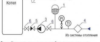
Rice. 4. Installation of an expansion tank in a system with one boiler: 1 – expansion tank; 2 – safety valve; 3 – circulation pump; 4 – filter; 5 – check valve; 6 – shut-off valve; 7 – air vent
In this case, the expansion valve is located on the return pipeline of the system, which allows it to be operated at a lower coolant temperature than if it were installed on the supply line. This solution allows you to extend the service life of the device. Connecting a tank to the pump suction pipe protects the pump from cavitation.
Rice. 5. Installation of expansion tanks in a system with several boilers and automatic limitation of the minimum water temperature in the return pipeline (one tank is provided for each boiler): 1 – expansion tank; 2 – safety group (safety valve, pressure gauge, air vent); 3 – circulation pump; 4 – three-way mixing valve; 5 – check valve; 6 – shut-off valve; 7 – hydraulic arrow
This scheme provides for one expansion chamber per boiler. The capacity of each of them must be no less than that calculated for the entire system, i.e. if according to calculations she needs a tank with a capacity of 80 liters, then this should be the capacity of each of the installed devices. This is due to the fact that when operating at reduced power, when the burner of one of the boilers is turned off, the corresponding circulation pump also turns off and the three-way valve closes. In this case, there is no water circulation through the disconnected boiler, and the expansion tank installed on this boiler is isolated from the rest of the system. The expansion chamber remaining in operation must provide compensation for the expansion of the coolant throughout the entire volume of the system. This provision is also true when using two-way valves that perform the function of blocking boilers.
Rice. 6. Installation of an expansion tank in a system with several boilers and automatic limitation of the minimum water temperature in the return pipeline (one expansion tank for the entire system): 1 – expansion tank; 2 – safety group (safety valve, pressure gauge, air vent); 3 – circulation pump; 4 – three-way mixing valve; 5 – check valve; 6 – shut-off valve; 7 – hydraulic shooter
Hydraulic accumulator calculation
In water supply systems, a lot of problems are solved using a hydraulic accumulator, and calculations for each case are performed using different methods. The above algorithm for calculating a hydraulic accumulator allows you to select tanks for solving the two most popular problems and determines the initial pressure of the gas space, the pressure to turn on and off the pump.
The first option for calculating the hydraulic accumulator is with priority to the pump switching frequency. In systems with booster stations, well and booster pumps, a hydraulic accumulator tank is necessary to reduce the frequency of pump activation.
Water is an incompressible liquid, so even a short-term opening of one water tap in an apartment building can cause the pump to turn on. Frequent activation of the pump leads to rapid wear and failure.
The frequency of switching on is related to the electrical power of the pump, for example, pumps with a power of more than 8 kW are recommended to be switched on no more than 10 times per hour, pumps with a power of less than 5 kW - no more than 20 times per hour, and pumps whose power falls in the range from 5 to 10 kW no more than 15 times per hour. This dependence underlies the above calculation algorithm.
In addition to the pump power, many more factors influence the permissible switching frequency, for example, the greater the mass of moving parts, the lower the permissible switching frequency
Therefore, pay attention to the correspondence of the switching frequency values obtained as a result of selecting a hydraulic accumulator and the optimal frequency for the previously selected pump, and if necessary, repeat the calculation of the tank
The second option for calculating a hydraulic accumulator is with priority to the stored volume of water. Recommended for systems in which interruption of water supply is not allowed, but interruptions in the supply of electricity or water from centralized water supply systems occur.
Where is a hydraulic accumulator used? Purpose of the hydraulic accumulator
As already mentioned, a hydraulic accumulator for heating systems is a very important, necessary part of the heating system equipment. And not an ordinary, atmospheric one, but a closed-type system in which the coolant circulates in a closed loop. This feature underlies the design and application in the system.
A closed heating system, unlike an open one, has greater capabilities, but at the same time, it also has a number of disadvantages that must be compensated for by installing additional equipment. If in an open system it is enough to correctly calculate and install an expansion tank to receive excess coolant, then in a closed system it will not be possible to get by with a simple additional volume. The pressure created inside the circuit of a closed heating system when heating the coolant is also supplemented by the pressure of the circulation pump. This inevitably leads to pressure drops in the heating-cooling cycle. That is why, to compensate for such differences, a hydraulic accumulator is installed for heating systems.
The second important point that needs to be taken into account when considering the question of why a hydraulic accumulator is needed in a heating system is the need to have a special safety device. The essence of this point is that closed systems are characterized by critical differences in coolant pressure. Water hammer caused by failure of automatic protection or breakdown of shut-off valves, even in a small volume of liquid of 30-40 liters, can cause big problems. A hydraulic accumulator for a heating system is capable of reacting at such critical moments almost instantly and absorbing a certain volume of liquid, thereby eliminating the threat of system rupture due to water hammer.
The third point is that, unlike a classic open-top expansion tank, a hydraulic accumulator for heating systems maintains the set fluid pressure. In closed systems, the liquid is under pressure not only during heating and operation of the circulation pump; even when the boiler is turned off, the system maintains the set pressure. A decrease in the set minimum threshold inevitably entails automatic shutdown of the equipment, since safety devices will record a decrease in pressure and perceive this as an emergency. When setting up equipment, the hydraulic accumulator for heating systems is specially installed to maintain the required pressure level. Regardless of the temperature of the coolant and the operation of heating devices, it will maintain the pressure at the required level.