The correct functioning of the heating system depends on many factors, including the correctly selected elements of the system that are responsible for safety. Today, individual heating systems, in addition to the usual valves, sensors and control devices, are equipped with another device that performs several functions, including a safety function - a hydraulic accumulator. This device is so versatile that it has found its application not only in heating systems. This is also one of the most important elements of equipment for cold and hot water supply systems in a private home.
Correct selection
An interesting nuance: the name of this equipment does not depend on its design, but on the area of application.
When it comes to water supply, the tank is called a hydraulic accumulator. A container built into the heating with the same structural characteristics will be called a membrane or expansion tank. But it is important to take into account the information provided by the manufacturer. Each product has its own operating temperature and pressure:
- up to 4 atmospheres and up to 120 degrees Celsius - for heating;
- up to 12 atmospheres and up to 80 degrees – for water supply.
It is not the cheapest tank that is selected based on volume, but one that corresponds to the system parameters.
To normalize the pressure in the heating system, a number of devices are used. But the most important of them is the hydraulic accumulator. Its design makes it possible to automatically stabilize the coolant pressure when the temperature changes.
Purpose
The hydraulic accumulator is installed only for closed-type heating systems. They are characterized by high water pressure, which occurs due to its heating. Therefore, if the permissible value is exceeded, a compensation system is necessary. This is what the hydraulic accumulator is designed for.
It is a steel structure, which is internally divided into two chambers. One of them is designed to be filled with water from the heating system, and the second serves as an air compensator. To set the optimal pressure in the air chamber, a valve is provided in the accumulator. With its help, the degree of air injection is changed, thereby adapting the device to the parameters of a specific heating system.
The chambers are separated by an elastic membrane or rubber balloon. When the water temperature in the pipes rises above critical, a pressure surge occurs. The liquid, expanding, begins to press on the walls of the separation membrane. She, in turn, under the influence of this force, increases the filling volume of the water chamber. This leads to normalization of pressure within the entire system.
Connection rules, diagram
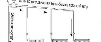
When installing a hydraulic accumulator, certain rules should be followed. First of all, you need to select an area in the heating main where it will be installed. Experts recommend installing the expansion tank in the return pipe with chilled water. But at the same time, it must be installed before the pumping equipment. The general installation diagram is as follows.
As you can see, a safety valve is installed at the outlet of the heating equipment to protect the line from differences in liquid pressure. It performs the same functions as a hydraulic accumulator, but is designed for higher pressure surges. An expansion tank is necessary to normalize heating operation at small pressure drops.
Before starting installation, please consider the following:
- Selecting an installation location. The main requirement for it is free access to the device. This is especially true for the air chamber control valve.
- There should be no other shut-off or control valves in the area between and the expansion tank. It can make significant changes in hydraulic resistance.
- The temperature in the room where the accumulator is installed should not be below 0°C.
- Its surface should not experience mechanical stress or external influences.
- The response of the pressure reducer to release air from the chambers must be set according to the parameters of the heating system.
Guided by these rules, you can install the expansion tank yourself. But at the same time, you should follow the connection rules, use products made of high-quality material and calculate the optimal tank volume.
To make the calculation, you need to know the total volume of the heating system, the optimal and maximum pressure in it, as well as the expansion coefficient of water. Formula for calculating the size of a membrane-type hydraulic accumulator:
- e – water expansion coefficient – 0.04318;
- C – total volume of the heating system;
- Pi – initial pressure;
- Pf – maximum pressure.
Let's consider an example of a calculation for heating with a total volume of 500 liters, an optimal pressure of 1.5 bar, and a maximum of 3 bar.
This technique will allow you to correctly select and connect an expansion tank for a closed heating system.
What is a hydraulic accumulator (HA)
It is unknown why this happened, but many authors believe that the heating accumulator is an expanzomat. And such a paradox is observed all the time. Well, why would an expansion tank, which only compensates for the expansion of water, be a hydraulic accumulator for heating systems?
If we are careful, the name itself already tells us that this device must accumulate liquid. Two devices meet this characteristic:
- hydraulic accumulator for cold water (expansomat);
- buffer capacity in the heating circuit (heat accumulator).
It is important not to confuse expanSomat with expanZomat (expansion tank). Perhaps this confusion lies in the similarity of names? It turns out that if we consider only the heating system, then the only hydraulic accumulator in it is the buffer tank. Although it is not intended for storing water, it fully corresponds to its name. Since there is still water in it and it heats up during the operation of the boiler, that is, it accumulates heat. After the heater stops working, the hydraulic accumulator for heating systems releases all the energy that it could accumulate.
The amount of this energy directly depends on the volume of the buffer tank. Accordingly, the more water it contains, the more heat it can hold. We’ve decided on the terminology, now let’s take a closer look at how it all functions.
How to choose the volume of a water supply accumulator
The more often the phases of operation and downtime of circulation pumps in the water supply system change, the higher the energy consumption and wear of components and parts in the hydraulic system equipment. Therefore, it is advisable to choose a hydraulic accumulator in order to reduce the number of starts of the pump electric motor. The main criterion in this choice is determining the optimal volume of the hydraulic tank. In this case, you can use both general (approximate) recommendations and very specific and accurate calculation methods.
To save energy and extend service life, the pump should be started no more than 30 times per hour. To roughly calculate the volume, you will have to take into account several more parameters:
- Pump capacity (QH). The average household pump has a capacity of approximately 2-3 m3/hour (2000-3000 l/hour);
- Useful volume of the hydraulic accumulator (VEF). This is the amount of liquid (water) that can be extracted from the hydraulic tank within min. and max. relay response pressure. In life, it makes up about 40% of the total capacity.
To ensure this condition, you need to select a GA with a total volume of at least:
V_min=Q_H/(30∙V_EF)=(2000…3000)/(30∙0.4)=170…250l
If the volume of water in the accumulator is used as a reserve, for example in the absence of electricity, a tank with a capacity of 24 liters or more is sufficient for a family of 1-2 people. For three consumers, tanks from 50 liters are recommended, and for four or more - from 100 liters.
It would seem that the larger the tank volume, the better. But do not forget that the water supply is just an additional bonus and the desire to increase it may have disadvantages:
- Such a hydraulic tank takes up a lot of space, which means you will have to have a large room to accommodate it.
- With a large volume and low consumption, the water in the tank may stagnate.
- It is not a fact that a minimum number of electric motor starts will extend the life of the pump
Functional load
His job is as follows:
- using a pump, water , under pressure, is supplied to the accumulator membrane,
- when the permissible pressure threshold level is reached, the relay deactivates the pump and the liquid stops flowing,
- when water is drawn, the pressure drops slightly , and the pump turns on automatically, and the liquid is again supplied to the membrane.
The efficiency of the unit depends on the size of the hydraulic tank. The larger its volume, the more productive the mechanism as a whole will function.
Do you know in what cases the owner will need a water supply station for a private home? In this useful article, read recommendations for choosing and how to calculate the power of the water supply unit.
About sewer and corrugated pipes for external sewerage is written here.
On the page: https://ru-canalizator.com/septiki/stochnye-vody/drenazhnaya-gofrirovannaya.html read about drainage, corrugated, perforated pipes with 200 mm geofabric.
If necessary, the pressure switch can be adjusted in the mode you need.
Air dissolved in the liquid substance, which accumulates in the membrane over time, can reduce the performance of the hydraulic accumulator
Therefore, as a preventive measure, it is necessary to periodically bleed off the accumulated air (various types of Mayevsky taps for cast iron radiators are described in this article).
How often should this procedure be performed??
It all depends on the volume of the tank and the frequency of its use. On average, this is once every two to three months.
Connecting a hydraulic tank is a minimum of difficulties
Self-installation of a hydraulic accumulator into the water supply system does not cause any serious problems. If the device is connected to networks with surface-type pumping equipment, the procedure will be as follows:
- Measure the pressure inside the accumulator. Its value should be 0.2–1 bar less than the pressure of the pump start relay.
- Prepare a fitting to connect the relay, hydraulic tank, pressure gauge and pump into one circuit. Nuance. Take a fitting with five outlets. An “extra” input will be required to connect a water pipe.
- Buy a relay for adjusting the pressure, as well as a fluoroplastic sealing material (FUM tape) or tow with.
- Connect the fitting to the tank using a flange (it must have a bypass valve) or a rigid hose.
- Screw on all parts of the system one by one. The last connection is made to the pipe that leads to the pumping device.
The installed tank should be checked for leaks. If there are any, you need to additionally seal the joints of individual elements of the device with FUM tape or a suitable sealant.
When using a hydraulic tank in systems with a submersible pump, it is necessary to take into account that the latter is installed directly in the place from which water enters the residential building (in a well, well). This scheme is potentially unsafe. There is a high probability of water “rolling back” to the source. How to avoid this? Quite simply - by installing a special check valve. It is placed directly on the pump in front of the water pipe. The procedure for connecting the hydraulic tank will be similar to the diagram described above. But with one change. First you need to install a check valve. And only after that connect all elements of the hydraulic accumulator to the water supply network.
Choose and install a hydraulic tank in your home to never have problems with your autonomous water supply system!
A hydraulic accumulator is a membrane expansion tank suitable for use with drinking water in water supply systems.
What then can go wrong there, is there any point in overpaying for the brand and are all hydraulic accumulators really the same?
In this article we will look at how some hydraulic accumulators may differ from others, and most importantly, we will understand what factors influence their cost
.
Why is such a drive needed?
If there is a hydraulic tank, the pump on-off cycle occurs only when it is necessary to fill the tank with a sufficient supply of water. If there were no hydraulic accumulator, the pump would turn on every time one of the household members opens the tap. The presence of a storage tank in the system allows:
- significantly increase the service life of the well pump;
- prevent harm from possible water hammer in the system;
- maintain a certain pressure in the system;
- prevent breakdowns of elements of the water supply system and plumbing equipment.
It is obvious that hydraulic accumulators for closed water supply are simply necessary. The role of the storage tank in the water supply system is described in detail in the following video:
The fundamental difference between a hydraulic accumulator and a compensation tank is determined by functionality. The hydraulic accumulator is designed to protect water supply systems, the expansion tank is designed to compensate for the thermal expansion of water. Different tasks place different demands on the design of units, so do not be deceived by external similarities.
The main task of the expansion tank is to maintain stable pressure in the heating circuit, adjusted for the thermal expansion of water. Liquids, like gases, increase in volume when heated, but are not able to compress. When the water becomes crowded, it strives for freedom, regardless of obstacles. The ending is predictable: a leak at the joint or a pipeline rupture. To prevent accidents, it is necessary to install a compensating tank in which excess water is collected.
The hydraulic accumulator performs protective functions in the water supply system , compensating for pressure drops in the network when the pump is turned on and off. This way it is possible to avoid water hammer, which shortens the life of the system. In addition, pumping equipment cannot operate continuously, so it is important to have a supply of water in case of a sudden power outage or pump breakdown.
At the same time, the hydraulic tank maintains sufficient pressure in the system during downtime of the pumping equipment. Until the pressure in the network drops to a critical level, the pumps rest - there is no need to start them every time someone opens the tap. The less on and off, the longer the pump will last. Of course, not all hydraulic accumulators are equally effective in their jobs - it is important to choose the right unit and accessories for the tank, taking into account the characteristics of the pumping equipment, the number of water points and the estimated water flow in the system.
On the Internet you can find formulas for determining the optimal volume of a water storage tank, but sometimes adjustments need to be made to the calculation methodology for operating conditions. For example, in case of frequent power outages, the volume of the vessel is selected with a reserve - but just enough to prevent stagnation of water. If you do not have enough knowledge and experience to take into account all the nuances and install the hydraulic tank yourself, contact specialists for help.
It's all about the membrane: design differences between hydraulic accumulators and expansion tanks
At first, the compensation tanks were made open, but later it turned out that such an engineering solution created new problems. Firstly, water constantly evaporates, and its losses need to be replenished. Secondly, no one has canceled the corrosive effect of oxygen. Thirdly, in open circuits it is more difficult to control the pressure. Finally, installing the tank costs a pretty penny, since the structure has to be insulated.
The emergence of durable and elastic membrane materials suggested a way out of the engineering impasse, making it possible to manufacture closed expansion tanks that do not allow oxygen to pass through. The problems of maintaining a constant water level and regulating pressure were solved in a similar way. In addition, the closed design has simplified the installation and maintenance of expansion tanks - from now on the unit can be installed not only at the top point of the system, but where it is more convenient for you.
The diaphragm membrane divides the capacity of the compensation tank into two parts. The upper compartment is filled with coolant, and air is pumped into the lower compartment, tightly pressing the diaphragm to the walls of the tank. An increase in the volume of coolant when heated compresses the air, allowing water to flow into the upper compartment of the tank.
Hydraulic accumulators are also equipped with membranes, but their shape and location are completely different. A balloon membrane, similar to a pear, is placed inside the vessel, which is attached between the flanges, eliminating contact of water with the inner surface of the tank. This is why the use of expansion tanks in water supply systems is unacceptable: if drinking water comes into contact with the walls of the tank, its quality will be unacceptable - for example, rusty water may flow from the tap.
Until the pressure of incoming water balances the air pressure between the walls of the vessel, the membrane expands, trying to fill the entire capacity of the accumulator. Air pressure is regulated by a nipple. At the top of the vessel there is a pipe to which an air vent and a safety valve are connected.
Since the membranes of expansion tanks and hydraulic accumulators operate under different conditions, the requirements for materials will be different. Thus, heat resistance is important for a diaphragm membrane, since the water temperature in heating systems reaches 90°C.
For balloon membranes, the priority is dynamic elasticity and resistance to frequent repetition of stretching and compression - from 5 to 15 cycles per hour in normal mode. Since the membranes of hydraulic tanks come into contact with drinking water, they are made of food-grade rubber with minimal diffusion. Resistance to thermal influences is not particularly important - the water temperature in cold water supply networks does not exceed 30°C.
Which membrane is better?
Based on the properties of the membranes, we can draw a conclusion about the permissible areas of application of the units. If you install a membrane accumulator in a heating system, the balloon membrane will quickly fail. But expansion tanks are successfully used in automatic fire-fighting installations as vessels for fire-extinguishing liquids or powder fire extinguishing modules.
Different materials are used to make membranes:
- NATURAL – natural rubber, compatible with industrial and drinking water; has high dynamic elasticity, although partial diffusion may occur as wear occurs;
- BUTYL – butyl rubber for expansion tanks and hydraulic accumulators. The material is more resistant to diffusion compared to rubber, but loses in elasticity;
- EPDM – ethylene propylene rubber; its characteristics are similar to butyl rubber, but more permeable to water. Like rubber, it can be used with drinking and industrial water;
- NITRIL – has anti-corrosion properties and withstands the action of active environments;
- SBR is a membrane rubber for expansion tanks; it is not stretchable enough for installation in a hydraulic accumulator.
Synthetic rubbers are designed to operate at temperatures from -10 to 100°C; rubber has an operating temperature range that is an order of magnitude smaller – from -10 to 50°C.
Now that you know what dictates the design differences between the elements of heating and water supply systems, not a single seller will confuse you. You yourself will figure out which unit you need - an expansion tank or a hydraulic accumulator. Carefully study the technical data sheets of the proposed models and make the right choice!
How a hydraulic accumulator works - simple and reliable design
A stable functioning water supply system of a private home is the merit of its owner. People who have experienced the installation and operation of autonomous water supply networks can imagine how difficult it is to avoid interruptions in the water supply in such complexes. Sometimes just one pressure surge is enough for expensive equipment connected to the water supply (for example, a water heater, a dishwasher) to fail. There is only one solution to such a problem - installing a hydraulic accumulator. It maintains a given pressure in the system, creates a certain supply of water and eliminates the risk of breakdown of household electrical equipment.
The need to install such a device is obvious.
The design of the hydraulic accumulator is quite simple. It is made in the form of a metal tank, inside of which a rubber membrane is installed. The latter is visually similar to a pear. The membrane is fixed to the hydraulic tank body by means of a special flange with a pipe. Water accumulates in the bulb under pressure. The space between the battery housing and the membrane is filled with compressed air (if we are talking about household devices) or an inert gas composition (industrial hydraulic tanks). The pressure in the system is maintained at 1.5–3 bar. Air can be pumped into a hydraulic accumulator at home using a regular car or even bicycle pump.
The devices under consideration are usually divided into three types:
- 1. For cold water supply systems. The device supplies water and stores it, protects pumping equipment from early wear and tear caused by frequent system switching on and off, and protects electrical equipment in the house from water hammer.
- 2. For hot water. Such a hydraulic accumulator for water supply systems can operate in high-temperature environments without problems.
- 3. Expansion tanks. They are designed for closed water heating systems.
The design and operating principle of all these devices are identical. We will talk about how such equipment functions further.
Balloon or membrane
Hydraulic accumulators are divided into two main types - membrane and balloon. The principle of operation of both types is similar - an elastic film of rubber expands or contracts under pressure from water and compressed air. The main difference is that in a membrane tank, water coming from the well comes into contact with the metal walls of the tank, which can potentially lead to corrosion. In a tank with a rubber cylinder, water comes into contact only with the cylinder itself, without touching the metal walls. The absence of conditions for the development of corrosion extends the life of the balloon accumulator.
An additional convenience is that the cylinder, unlike the membrane, is a replaceable part. Carrying out the replacement will not cause any difficulties - even a non-specialist can do it. As a result, servicing a hydraulic accumulator with a cylinder will be cheaper. Taking into account the above factors of practicality and reliability, cylinder accumulators are the optimal solution for individual water supply.
An important factor when choosing a hydraulic accumulator is the cost of spare parts
Please note that some manufacturers may unreasonably inflate the price of components. For example, a rubber cylinder can cost half or even more of the cost of the entire hydraulic accumulator
Types of hydraulic water tanks, divided by location and other parameters
Let's present this section in tabular form for ease of understanding:
| Separation | Designation | Peculiarities |
| Location type | Horizontal | The volume of such tanks is larger. The vertical position allows the air release valve to be installed from above. This makes maintenance easier. The only limitation in installation is the volume of the room. |
| Vertical | Compact options in which a tap is installed to vent air. The disadvantage is that in some models you have to completely drain the water to bleed the air, which is not economical. | |
| Energy storage | Pneumatic accumulation | Diaphragm, balloon or piston. The problem arises when the partition wears out - expensive and labor-intensive repairs are required. |
| Balloon or pear | Most popular. When worn out, the pear is replaced with a new one independently, without the involvement of professionals. | |
| Mechanical storage | Weight or spring. Work is based on kinetic energy. Quite voluminous and work autonomously. |
Installation of a heat accumulator
Improving the heating operation with additional devices with your own hands will make it necessary to carry out the following work:
Make a detailed diagram
When developing a drawing, you need to take into account where the heating accumulator is located, the insulating layer, the height of the battery tank, the presence of drainage for water disposal - factors for reducing heat loss; Integrate a collector-distributor into the system, ensuring that the various systems are connected correctly; After connecting the pipeline parts, check the tightness of the connections; Connect the storage tank; Connect the circulation pump; After completing the assembly work with your own hands, test the tightness and correctness of the connections. To prevent the pump from turning on every time a tap is opened in the house, a hydraulic accumulator is installed in the system
It contains a certain volume of water, sufficient for a small flow rate. This allows you to practically get rid of short-term pump starts. Installing a hydraulic accumulator is not difficult, but a number of devices will be required - at a minimum - a pressure switch, and it is also desirable to have a pressure gauge and an air vent
To prevent the pump from turning on every time a faucet is opened in the house, a hydraulic accumulator is installed in the system. It contains a certain volume of water, sufficient for a small flow rate. This allows you to practically get rid of short-term pump starts. Installing a hydraulic accumulator is not difficult, but you will need a few more devices - at least a pressure switch, and it is also desirable to have a pressure gauge and an air vent.
How does a water heat accumulator work?
A water accumulator for heating performs the following tasks:
- energy storage;
- stabilization of the temperature of the working fluid;
- reducing the number of furnace loads;
- increasing boiler efficiency;
- reduction of fuel consumption.
How can one device perform so many functions? In fact, everything is quite simple, because all these processes are interconnected.
As a result of using a heat accumulator, you get some advantages. Your system will be stable, and its operation will be less troublesome, because adding firewood every four hours is not an option for permanent housing.
The accumulation of energy occurs in those moments when the fire burns. In the absence of a HA, the water in the circuit can heat up beyond what is necessary, because there is nowhere to put the excess heat. And after combustion stops and the fuel begins to smolder, the temperature of the working fluid decreases. It turns out that surges constantly occur in the batteries, and accordingly, in the room too. In general, nothing good.
Optimal pressure in the accumulator
The air pressure in the hydraulic tank in the absence of water is one of the main operating parameters. This parameter is different for each hydraulic accumulator and is indicated in its technical data sheet. Small fluctuations from the nominal value are allowed, but significant excess or decrease in pressure should be avoided, as the service life of the rubber cylinder (membrane) is reduced. For the water supply system to operate, the pump activation pressure must be at least 0.5 bar higher than the operating air pressure in the accumulator.
The nominal pressure may be affected by the number of storeys in the building. For example, if the accumulator is located in the basement of a two-story building, then the minimum pressure in the water supply system should be 2 bar. 1 bar of pressure is needed to raise water to a height of 10 m, another 1 bar is needed to create the required water pressure in the consumer’s tap. In our case, 10 m is the average height difference between the basement and the second floor. Taking into account the pressure of 0.5 bar created by the well pump, the operating pressure in the accumulator should be equal to 1.5 bar.
The pressure values for turning on and off the well pump can be set programmatically in the automatic control unit. The sensor is a pressure switch. Correctly set pressure values will reduce the frequency of pump activation and maintain the required pressure in the water supply system. Effective operation of the accumulator occurs if the difference between the pressure on and off the pump is from 1.5 to 4.5 bar.
Setting up a hydraulic accumulator for water heating
When purchasing equipment, you should remember that the tank is under pressure. Therefore, during installation it is necessary to be as careful as possible and under no circumstances vent the air pumped into the compartment. After the installation of all elements of the heating circuit has been completed and a test filling of it with coolant has been completed, it is necessary to adjust the gas pressure in the accumulator housing. With excess pressure, the coolant simply will not flow into the membrane cavity, and with reduced pressure in the chamber with gas, the unit will not be able to effectively perform its functions.
Checking the correct setting of the hydraulic accumulator is done using a pressure gauge. The coolant is pumped into the system and its pressure is checked using the boiler pressure gauge. Having reached the recommended level, the coolant supply valve is closed and the pressure in the air chamber of the battery is checked using a pneumatic manometer. For normal operation of the system, it is recommended to set the pressure in the tank 0.2-0.3 bar less than in the heating circuit. If you set the pressure in the air chamber at the same level as in the system, then when signs of an emergency appear, the membrane simply will not be able to accept the required amount of coolant. As liquid flows from the circuit into the membrane, the pressure in the tank will also increase, and the moment may be missed when it would be possible to prevent an accident by removing literally 2-3 liters of liquid from the system. And at reduced pressure, the effect is the opposite; the membrane reacts very sensitively to changes in pressure in the circuit and quickly removes peak loads, absorbing liquid much faster.
When adjusting the pressure, you can reduce it simply by pressing the nipple and releasing a certain volume of air, but you can add it simply by connecting a car pump to the nipple and making a few pumps.
The air pressure in the air chamber is considered optimal when the operating fluid pressure in the system is in the range of 1.2-1.3 bar, an indicator equal to 1.0-1.1 bar.
Functions, purpose, types
Installation location - in a pit or in a house
In the water supply system of a private house without a hydraulic accumulator, the pump turns on whenever water flows somewhere. These frequent starts lead to wear and tear on the equipment. And not only the pump, but the entire system as a whole. After all, every time there is an abrupt increase in pressure, and this is a water hammer. To reduce the number of pump starts and smooth out water hammer, a hydraulic accumulator is used. The same device is called an expansion or membrane tank, a hydraulic tank.
Purpose
We found out one of the functions of hydraulic accumulators - to smooth out water hammer. But there are others:
It is not surprising that most private water supply systems have this device - there are many advantages from its use.
Kinds
The hydraulic accumulator is a tank made of sheet metal divided into two parts by an elastic membrane. There are two types of membrane - diaphragm and balloon (bulb). The diaphragm is attached across the tank, a pear-shaped cylinder is secured at the inlet around the inlet pipe.
According to their purpose, they are of three types:
- for cold water;
- for hot water;
- for heating systems.
Hydraulic tanks for heating are painted red, tanks for water supply are painted blue. Expansion tanks for heating are usually smaller in size and lower in price. This is due to the membrane material - for water supply it must be neutral, because the water in the pipeline is potable.
Depending on the type of arrangement, hydraulic accumulators can be horizontal or vertical. Vertical ones are equipped with legs; some models have plates for hanging on the wall. It is the elongated upward models that are most often used when independently creating water supply systems for a private home - they take up less space. The connection of a hydraulic accumulator of this type is standard - through a 1-inch outlet.
Horizontal models are usually equipped with pumping stations with surface-type pumps. Then the pump is placed on top of the tank. It turns out compact.
Principle of operation
Radial membranes (in the form of a plate) are used mainly in gyroaccumulators for heating systems. For water supply, a rubber bulb is usually installed inside. How does such a system work? As long as there is only air inside, the pressure inside is standard - the one that was set at the factory (1.5 atm) or that you set yourself. The pump turns on, begins to pump water into the tank, and the pear begins to increase in size. Water gradually fills an increasingly larger volume, increasingly compressing the air that is located between the wall of the tank and the membrane. When a certain pressure is reached (usually for one-story houses it is 2.8 - 3 atm), the pump is turned off, and the pressure in the system stabilizes. When you open a tap or other water flow, it comes from the accumulator. It flows until the pressure in the tank drops below a certain level (usually about 1.6-1.8 atm). After which the pump turns on, the cycle repeats again.
If the flow rate is large and constant - you are filling a bathtub, for example - the pump pumps water in transit, without pumping it into the tank. The tank begins to fill after all the taps are closed.
A water pressure switch is responsible for turning the pump on and off at a certain pressure. In most hydraulic accumulator piping schemes, this device is present - such a system operates in optimal mode. We’ll look at connecting the hydraulic accumulator a little lower, but for now let’s talk about the tank itself and its parameters.
Large tanks
The internal structure of hydraulic accumulators with a volume of 100 liters and above is slightly different. The pear is different - it is attached to the body both at the top and bottom. With this structure, it becomes possible to fight the air that is present in the water. To do this, there is an outlet in the upper part into which you can connect a valve for automatic air release.
How to set it up correctly
The first thing you need to do when pumping air into the device is to disconnect it from the heating system (how to make titanium using wood with your own hands is written here), there should be no water in it.
It's no secret that any heating system must be equipped with an expansion tank, an indirect heating boiler (piping, diagram) or a hydraulic accumulator.
The device is connected to the return pipeline of the central main, as close as possible to the boiler room or boiler (installation in any other place is allowed).
In order for the unit to fulfill its intended purpose, it can even be connected using a regular flexible hose, which we use to connect the toilet tank.
But there are cases when it is necessary to increase the cross-section of the supply pipe:
- if the water is rusty and dirty, to prevent the formation of blockages and sand accumulation in the pipe (find out how to clean electric titanium here);
- if necessary, provide additional protection of the pipeline from hydraulic shocks. In this situation, the cross-section of the pipeline must exactly correspond to the main hollow products.
Sometimes, precedents occur when hoses made of low-quality material suffer from rusting. Then the connection quickly becomes unusable, it:
- cracks
- breaks.
Optimal size
If you need a device for the heating needs of a private home , we recommend buying a red device (it is specifically designed for this purpose).
Such mechanisms use rubber intended for technical needs; it has a long service life.
For blue products, not a membrane is used, but a pear made of “food” rubber
What is a hydraulic accumulator
A hydraulic tank (or hydraulic accumulator) is a water container with a rubber elastic membrane (resembling a pear) located inside the container and having a sealed connection to the metal body of the tank. This connection is made using a flange with a threaded connection to connect the device to the water supply. The cavity between the membrane and the metal body of the hydraulic tank is filled with compressed air, usually the pressure is 1.5-2 bar. Hydraulic accumulators are used to maintain constant pressure and create a water reserve in domestic or industrial conditions. It is this unit that provides the required pressure in the system when the pump is turned off.
Fig.1.
Hydraulic accumulator structure 1 – metal body; 2 – rubber membrane; 3 – flange with valve (passes air); 4 – nipple for pumping air into free space; 5 – cavity for compressed air; 6 – supports; 7 – platform for the pump. More details about the design of the hydraulic tank in the video: Return to content
Role in the heating system
The main tasks of the hydraulic accumulator:
- accumulation of “excess” coolant during its expansion;
- air removal;
- replenishment of volume in case of possible leaks or drop in water (antifreeze) level.
There are two types of tanks - open and closed type. The second option is used in most modern heating systems. This is a completely sealed hydraulic accumulator with a membrane or bulb (it is used in large containers).
Hydraulic accumulators are installed only for heating with a circulation pump, since this system is characterized by high operating pressure.
Peculiarities
The hydraulic tank is called a hydraulic accumulator or membrane tank. It is used to maintain a stable pressure level in the water supply system. The product also protects the pump from wear and the drainage system itself from water hammer. Thanks to the hydraulic tank, you can use water even in the absence of voltage.
Advantages of vertical hydraulic tanks:
- Protection of the pump from early wear.
- Maintaining stable pressure in the water supply system.
- Protection against water hammer that may occur during the start-up of alluvial equipment. Water hammer can damage the pipeline.
- Maintaining water reserves in the system.
Vertical type hydraulic accumulators have disadvantages, which include complex installation. Installation will require effort and some skill.
The principle of operation of the hydraulic tank and how it all happens
When the pumping equipment is turned on, water begins to flow into the membrane. The volume of the pear increases. This leads to the fact that the air in the accumulator housing (outside the membrane) is compressed and forms some pressure. When the specified value is reached, the electric pump is switched off at the command of the control relay. Compressed air presses on the water in the bulb and pushes it through the water supply. The consumer opens the tap. Water begins to flow through it, coming from a hydraulic tank under a given pressure.
After some time, there is less water in the membrane. Because of this, the pressure level also decreases. When it becomes minimal, the relay is activated again and the pump automatically starts. Then everything goes according to the scheme already described above. The pumping equipment starts more often, the smaller the hydraulic tank is used. The optimal capacity of a hydraulic accumulator for domestic use is 100 liters. In this case, the relay operates no more than 5–15 times in 60 minutes. With such indicators, wear of hydraulic equipment will be minimal
It is important to understand that more frequent pump starts lead to premature wear of the membrane and other battery elements
Water entering household hydraulic tanks most often rises from wells or specially equipped wells. This liquid is characterized by increased oxygen saturation. It can accumulate in the pear, released during the functioning of the home plumbing. Oxygen must be periodically removed from the system. For these purposes, in many models of hydraulic accumulators, a special valve is mounted on the body (in its upper part). If necessary, it independently releases excess oxygen.
Active use of the hydraulic tank often causes a decrease in air pressure. No equipment is insured against such natural wear and tear. Experts recommend completely emptying the battery and checking the pressure reading every 10–12 months. This simple procedure will guarantee comfortable use of water supply in a private home.
Principle of operation
The storage tank begins to accumulate excess heat in the upper part of the tank after the room is completely heated. As the accumulator cools, it gradually releases heat into the heating system.
The capacity of the hydraulic accumulator determines how many times during the day the solid fuel boiler will be loaded.
The operation of the storage tank is based on the use of high heat capacity of water, which, when cooled by 1 °C, releases several times more heat to heat 1 m2 of room.
To calculate the volume of the storage tank, use the ratio - 25 - 30 liters of tank per 1 kW of solid fuel boiler power.
For example, for a 20 kW boiler, the tank volume will be from 500 to 600 liters.
Accumulator volume
Do not buy a hydraulic accumulator based on what your friends or neighbors in the country have installed. Perhaps this model will not be effective for you. The volume of the hydraulic accumulator (like all other equipment!) should be selected only on the basis of the results of hydraulic calculations. The number of models on the market is quite large.
Is there an optimal hydraulic tank volume? As we have already said, only a hydraulic calculation can accurately indicate a specific model of hydraulic equipment that is optimally suited to your conditions. But the number of typical volumes for various models of hydraulic tanks is not so large. That is, if, according to the calculation results, you need a tank with a volume of 51.5 liters, then you will not be able to find such a tank on sale. You will be advised to purchase a 60 liter hydraulic tank. Extra liters of volume will not harm, and will even slightly increase the water supply and reduce the number of pump starts.
The experience of engineers selecting and installing water-lifting equipment tells us the following:
- A hydraulic accumulator with a volume of 25 liters can be installed in a water supply system for three consumers with a borehole pump productivity of 2 m3/h.
- in a system with a number of consumers of 4-8 and a pump capacity of 3.0-3.5 m3/h, a hydraulic tank with a volume of 60 liters is optimal.
- if the number of consumers is more than 10 and the pump capacity is 5 m3/h, then the optimal tank volume will be 100 liters.
Tank volume is the main selection criterion
The most important question is how to choose the volume of a hydraulic accumulator for water supply systems. To answer it, you need to bring together a lot of data. This includes the performance of the pump, the equipment of the house with water-consuming equipment, the number of people permanently living in the house, and much more.
But first of all, you need to decide whether you need this reservoir only to stabilize the operation of the system as a whole, or whether there is a need for a supply of water in case of a power outage.
Internal cylinders of different volumes
If the house is small and equipped only with a washbasin, toilet, shower and watering tap, and you do not live in it all the time, you don’t have to make complex calculations. It is enough to buy a tank with a volume of 24-50 liters, it will be enough for the system to work normally and be protected from water hammer.
In the case of a country house for permanent family residence, equipped with everything necessary for a comfortable life, it is advisable to approach the issue more responsibly. Here are a few ways you can decide on the size of your accumulator.
According to pump characteristics
The parameters that influence the choice of tank volume are the performance and power of the pump, as well as the recommended number of on/off cycles.
- The higher the power of the unit, the larger the volume of the hydraulic tank should be.
- The powerful pump pumps water quickly and turns off quickly if the tank volume is small.
- A sufficient volume will reduce the number of intermittent starts, thereby extending the service life of the electric motor.
To calculate, you will need to determine the approximate water consumption per hour. To do this, a table is compiled that lists all devices that consume water, their quantity and consumption rates. For example:
Table for determining the maximum water flow
Since it is almost impossible to use all devices at the same time, a correction factor of 0.5 is used to determine the actual flow rate. As a result, we get that you spend an average of 75 liters of water per minute.
How to calculate the volume of a hydraulic accumulator for water supply, knowing this figure, the performance of the pump and taking into account that it should turn on no more than 30 times per hour?
- Let's say the productivity is 80 l/min or 4800 l/h.
- And during peak hours you need 4500 l/h.
- When the pump operates non-stop, its power is quite sufficient, but it is unlikely to work for a long time in such extreme conditions. And if it turns on more than 20-30 times per hour, then its resource will run out even faster.
- That’s why we need a hydraulic tank, the volume of which will allow us to turn off the equipment and give it a break. At the indicated cycle frequency, the water supply should be at least 70-80 liters. This will allow the pump to remain idle for one minute out of every two, pre-filling the reservoir.
According to the formula of the minimum recommended volume
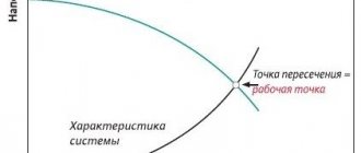
To use this formula, you need to know the settings of the pressure switch, which turns the pump on and off. The following picture will help you understand:
Changes in pressure in the accumulator when turning the pump on and off
- 1 – initial pressure Pair (with the pump turned off);
- 2 – water flow into the tank when the pump is turned on;
- 3 – reaching the maximum pressure Pmax and turning off the pump;
- 4 – water flow with the pump turned off. When the pressure reaches the minimum Pmin, the pump turns on.
The formula looks like this:
- V = K x A x ((Pmax+1) x (Pmin +1)) / (Pmax - Pmin) x (Pair + 1), where
- A is the estimated water flow (l/min);
- K – correction factor from the table, determined depending on the pump power.
Table for determining the correction factor
You must set the values of the minimum (starting) and maximum (switching off) pressure on the relay yourself, depending on what pressure you need in the system. It is determined by the farthest and highest water collection point from the accumulator.
Approximate ratios of pressure switch settings
To adjust the pressure switch, you need to know how to inflate a hydraulic accumulator for water supply systems with air, or bleed off excess air. To do this, you will need a car pump, which is connected to the tank through a spool.
Now you can calculate the volume. For example, let's take:
- A = 75 l/min;
- Pump power 1.5 kW, respectively K = 0.25;
- Pmax = 4.0 bar;
- Pmin = 2.5 bar;
- Pair. = 2.3 bar.
We get V = 66.3 liters. The nearest standard hydraulic accumulators in terms of volume have a volume of 60 and 80 liters. We choose the one that is larger.
This is interesting: How to choose a wood splitter (video)
Is there a difference between vertical and horizontal hydraulic accumulators?
The tanks described in the article are mounted in two ways: vertically and horizontally. The specific type of hydraulic accumulator should be selected based on how compactly it will fit into the area that will be allocated for its installation. In addition, in vertical and horizontal devices, air is removed from the membrane differently
It is important. In vertical devices, the release of accumulated oxygen is carried out using a safety valve (we have already mentioned it)
But in horizontal ones it is necessary to additionally install a special pipeline to remove air. Structurally, the additional line consists of a ball valve, a drain and a nipple (it is called an outlet valve).
Please pay attention to the following nuances:
- Vertical accumulators with a volume of less than 100 l are never equipped with a safety valve. Bleeding air in such devices is carried out by completely emptying them.
- It makes more sense to connect horizontal hydraulic tanks to external pumps, and vertical ones to submersible ones installed inside a room specially designated for them.
The ability to bleed air must be present in any hydraulic tank. If you do not free the equipment from the oxygen accumulated in it, air pockets will very quickly appear in the water supply. They will not allow you to effectively operate your home water supply system.
Connecting the accumulator to the system
Typically, the water supply system of a private home consists of:
This scheme may also include a pressure gauge for operational pressure control, but this device is not necessary. It can be connected periodically to carry out test measurements.
With or without five-pin fitting
If the pump is of a surface type, the hydraulic accumulator is usually placed next to it. In this case, the check valve is installed on the suction pipeline, and all other devices are installed in one bundle. They are usually connected using a five-pin fitting.
It has terminals with different diameters, just for the devices used for tying the hydraulic accumulator. That’s why the system is most often assembled on its basis. But this element is not at all necessary and everything can be connected using ordinary fittings and pieces of pipe, but this is a more labor-intensive task, and there will be more connections.
How to connect a hydraulic accumulator to a well - diagram without a five-pin fitting
With one inch outlet, the fitting is screwed onto the tank - the pipe is located at the bottom. A pressure switch and pressure gauge are connected to the 1/4 inch outlets. The remaining free inch terminals are connected to the pipe from the pump and wiring to consumers. That's all for connecting the gyroaccumulator to the pump. If you are assembling a water supply circuit with a surface pump, you can use a flexible hose in a metal winding (with inch fittings) - it is easier to work with.
A visual diagram of connecting the pump and accumulator - use hoses or pipes where necessary
As usual, there are several options, the choice is yours. The hydraulic accumulator is connected to the submersible pump in the same way. The whole difference is where the pump is installed and where the power is supplied, but this has nothing to do with the installation of the accumulator. It is placed in the place where the pipes from the pump enter. Connection is one to one (see diagram).
How to install two hydraulic tanks on one pump
When operating the system, sometimes owners come to the conclusion that the available volume of the accumulator is not enough for them. In this case, you can install a second (third, fourth, etc.) hydraulic tank of any volume in parallel.
There is no need to reconfigure the system; the relay will monitor the pressure in the tank on which it is installed, and the viability of such a system is much higher. After all, if the first accumulator is damaged, the second one will work. There is another positive point - two tanks of 50 liters each cost less than one of 100. The point is that the technology for producing large-sized containers is more complex. So it is also more economical.
How to connect a second accumulator to the system? Screw a tee onto the input of the first one, connect the input from the pump (five-pin fitting) to one free output, and connect the second container to the remaining free one. All. You can test the circuit.
To avoid depressurization of joints and heating equipment, a hydraulic accumulator or expansion tank is installed in the system. This unit provides constant pressure - when it expands, water flows into it and does not harm the system.
How to seal connections in heating and water supply pipelines
On sale you can find many different materials that are designed to seal pipeline joints. The question arises: which material should be used in which cases? And also, how to properly use this or that seal?
It is often possible to use two or more thread sealants at once; then clarification is required as to which to prefer. The recommendations given should help to understand these issues and find a solution that will ensure sufficient reliability of the connection of pipes and threaded fittings for the entire period of operation.
Linen winding
Flax is a cheap material for threaded joints that creates a very high-quality seal. The only thing is that it cannot be used in all cases.
It is intended for connecting metal parts, as it creates significant density. It is very durable; the force applied by the keys to the two parts being connected is required to be significant.
Therefore, flax is not compacted:
- plastic parts - the tightening torque exceeds the strength of the material, the parts will be crushed and destroyed, at least the threads.
- parts in which a metal coupling with a thread is embedded in a plastic (polypropylene) shell, due to the danger of rotation (disconnection).
For all metal products, flax is the No. 1 material for winding threaded joints.
Next, let's look at how to apply it correctly.
Flax cannot be used “dry”; it must be lubricated with a special plumbing paste. It is applied either directly to the thread or to wound flax.
People's experience also suggests that sunflower oil can be used instead of paste, but the quality of the joint does not decrease, at least there is no such information.
A strand is separated from the flax and wound along a thread along each stream. Winding is done tightly and neatly. There should be no protruding hairs. The first two turns are not filled, but a shoulder is made at the end of the thread.
Special plumbing thread
A special thread for seals, of high strength (cannot be torn by hand), wound on spools, is sold in stores. Its main drawback is its high price, but otherwise it has solid advantages.
- It can be used on any parts, the tightening torque is less compared to flax, so you can also wrap plastic.
- It seals very well and can be used even on torn threads.
If it were not for the cost of this material, then only such plumbing thread would be used for joints.
Winding is carried out in exactly the same way as with flax - the first two turns of the thread are left empty so that the parts can be joined, and then winding is carried out along each thread of the thread, at the end of the winding - a double layer, i.e. shoulder
Fum tape
Fum tape is not suitable for creating reliable connections on pipelines. The material is not very durable; there is no sufficient density in the threaded connections of metal products with it. But for plastic connections that will be dismantled, for example, a summer pipeline for irrigation, fum tape is the most suitable sealant.
With fum tape, the parts to be joined can be wrapped by hand. In this case, a small density of the joint along the thread occurs, so that leaks do not occur for some time. A slight tightening force does not provide sufficient tightness and does not guarantee that the joint will not leak. For fixed connections, especially if they will be inaccessible during operation, it is recommended to use other materials.
Heating in the house can be done independently - the main installation issues
If the connection to the fum tape, which is already in operation, is turned, a leak will most likely occur. This is a serious drawback, considering that rotation does not require much effort.
At the household level, fum tape can be used (and is popular due to its low cost, ease of use, and low effort) for connections that are in plain sight - when connecting showers, taps, etc. Which heating scheme is best to use in a private house?
Plumbing adhesive sealant for threaded connections
The material is special, not exactly cheap, seals well, no cases of leakage have been recorded after its correct use. But only after the wrong...
The obvious disadvantage of sealant adhesive is that the quality of the joint will depend on the “human factor” more than with windings. The fact is that glue does not work well on oily surfaces.
Where do greasy surfaces come from? It could simply be carelessness - they dropped oil on the thread or rubbed the part in oil with their hands. Parts can be stored in a lubricated state (primarily steel ones). But the main thing is that a lubricant is used when cutting threads. After such an operation on steel parts, glue and sealant are completely unsuitable.
Please note that there are glue samples with which undocking the pipes requires heating of more than 100 degrees. Such heating is often difficult, not safe, plastic can be damaged, etc. Therefore, the adhesive-sealant is still selected according to the circumstances.
The glue is easy to apply. It is applied only immediately before joining, squeezed out of the tube onto the thread and smeared with your finger over the entire thread without skipping.
In what cases should you choose glue?
- When connecting plastic parts to metal ones, glue will be preferable. But such a connection does not occur often.
- The second case is when access to the docking site will be difficult. It is better to place such a connection with glue, and lubrication is carried out generously, without saving, on both parts being joined.
Winding Features
Winding on threads requires great care. The thread must be filled in an even layer without gaps, and there must be sealing material in each groove. It is laid to the end of the thread, where a shoulder is formed from it.
The main tightening of threaded connections occurs on the last two threads. On parts, more often than not, the last two turns of the thread are not cut to the full depth. Therefore, in this place the material is wedged between the two parts very tightly.
It would be nice if, when carrying out work, you organize additional (cross-cut) quality control of the flax winding. This is especially true when several dozen similar connections are performed at once.
conclusions
- For those who are constantly engaged in installation, it is recommended to always have flax, plumbing thread and adhesive sealant with you in order to quickly and efficiently complete any connection. It is recommended to apply all this in accordance with the tips given above.
- When doing work at home with your own hands, when doing something simple and in plain sight, you can use cheap fum tape, but you need to wrap more. When installing entire systems with your own hands, it is better to use flax (with vegetable oil) on metal, and for small volumes of work it is even better to use thread. Maximum attention should be paid to the quality of winding on the thread.
What should never be used to seal threaded connections:
- There is no need to use simple silicone; it is designed for flange connections.
- There is no need to use paints, whitewash, or red lead, which are of little use, but make the connections semi-dismountable - this is long outdated.