Testing of heating and heat supply systems
The heating system
is tested after completion of installation work. But first, all plumbing systems must be flushed.
Before testing, the compliance of the heating system
project, carry out an external inspection of pipelines, connections, equipment, instruments, fittings.
Heating systems are tested
in general and individual types of equipment, and also regulate them. Based on the test results, reports are drawn up.
Testing of heating systems, heat supply
performed by hydrostatic and manometric (pneumatic) methods.
Hydrostatic testing of the heating system
is carried out by filling all elements of the system with water (with complete removal of air), increasing the pressure to test pressure, holding the system under test pressure for a certain time, reducing the pressure and, if necessary, emptying the system. Hydrostatic testing is safe: the system is tested under conditions closest to operating conditions. However, such a test requires water to be supplied to the building to fill the plumbing system, which is unacceptable. If the tightness is broken, flooding of premises and soaking of building structures is possible; In winter, water in the pipes may freeze and “defrost”.
Therefore, hydrostatic testing of heating systems
, heat supply, boilers, water heaters are performed at a positive temperature in the premises of the building. The temperature of the water used to fill the system must not be lower than 278°K (5°C).
Hydrostatic heating tests
carried out before finishing the premises.
Pressure testing of the heating system
In many respects, they do not have the disadvantages of hydrostatic tests, but they are more dangerous, since if pipelines or system elements are accidentally destroyed under the influence of compressed air, their pieces can fall into the people conducting the tests.
Gauge heating tests
carried out by filling
the heating system
with compressed air at a pressure equal to the test one, and maintaining it under this pressure for a certain period, then the pressure is reduced to atmospheric pressure.
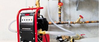
For testing, a pneumohydraulic unit TSTM-10 is used in the form of a biaxial trailer, on which a tank with a volume of 2.5 m3 and all testing equipment are mounted.
Heating systems testing
.
Acceptance of heating boiler rooms is carried out on the basis of the results of hydrostatic or pressure testing, and heating systems
- on the basis of the results of hydrostatic and thermal tests, as well as external inspection of installed devices and equipment.
Heating systems
are tested for tightness (but not for strength) by the manometric method under an excess air pressure of 0.15 MPa to detect installation defects by ear and then with a pressure of 0.1 MPa for 5 minutes (in this case, the pressure should not decrease by more than 0. 01 MPa).
Hydrostatic testing of a water heating system
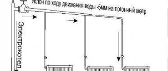
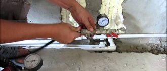
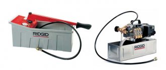
carried out upon completion of its installation and inspection. To do this, fill the system with water and completely remove air from it by opening all air collectors, taps on risers and at heating devices. Fill the system through the return line, connecting it to a permanent or temporary water supply. After filling the system, close all air collectors and turn on a manual or driven hydraulic press, which creates the required pressure.
Water heating systems
are subjected to hydrostatic pressure equal to 1.5 working pressure, but not less than 0.2 MPa at the lowest point. During the test, the boilers and expansion vessel are disconnected from the system. The pressure drop during the test should not exceed 0.02 MPa for 5 minutes. The pressure is monitored with a tested and sealed pressure gauge with scale divisions at 0.01 MPa. Any minor faults found that do not interfere with the hydrostatic test are marked with chalk and then corrected.
Source
Preparatory stage before testing
Before testing the system, the pipes are inspected to identify problems visually. This is how the pipeline’s readiness for testing is determined.
To prepare for testing:
- Carefully inspect the joints.
- Determine the correct installation of the fittings.
- Check supporting structures and suspensions.
- Locking devices are tested to see how freely they close and open.
- Determine how quickly air can be removed from the pipeline.
Suitable air temperature during testing is not lower than 15 degrees above zero. Before starting work, external pipelines are purged to remove contaminants inside the system.
Source
INTERNAL COLD AND HOT WATER SUPPLY SYSTEMS
4.4. Internal cold and hot water supply systems must be tested by hydrostatic or manometric method in compliance with the requirements of GOST 24054-80, GOST 25136-82 and these rules.
The test pressure value for the hydrostatic test method should be taken equal to 1.5 excess operating pressure.
Hydrostatic and pressure testing of cold and hot water supply systems must be carried out before installing water taps.
Systems are considered to have passed the tests if, within 10 minutes of being under test pressure using the hydrostatic test method, no pressure drop of more than 0.05 MPa (0.5 kgf/cm 2) and drops in welds, pipes, threaded connections, fittings and leaks are detected water through flush devices.
At the end of the hydrostatic test, it is necessary to release water from the internal cold and hot water supply systems.
4.5. Manometric tests of the internal cold and hot water supply system should be carried out in the following sequence: fill the system with air at a test excess pressure of 0.15 MPa (1.5 kgf/cm 2); if installation defects are detected by ear, the pressure should be reduced to atmospheric pressure and the defects eliminated; then fill the system with air at a pressure of 0.1 MPa (1 kgf/cm2), hold it under test pressure for 5 minutes.
The system is considered to have passed the test if, when it is under test pressure, the pressure drop does not exceed 0.01 MPa (0.1 kgf/cm 2 ).
Determination of additional water volume
After performing a leak test, as a rule, the additional volume of liquid in the system should be calculated. This process takes place in the following sequence:
- The pressure level in the structure is again increased by pumping liquid from the measuring tank. The pressure indicator should be the same as during a hydraulic test, that is, exceed the standard indicators by 1.25–1.5 times.
- The time when the leak test ended must be remembered.
- At the third stage, the final water level in the measuring tank is measured.
- Next, the time period that the communication check took (in minutes) is determined.
- Calculation of the volume of liquid pumped from the measuring tank (for 1 case).
- Calculation of the difference between the liquid pumped up and removed from the pipeline (for case 2).
- Calculation of actual consumption of additionally pumped liquid using the formula: qn=Q/(Tk-Tn).
HEATING AND HEAT SUPPLY SYSTEMS
4.6. Testing of water heating and heat supply systems must be carried out with the boilers and expansion vessels turned off using the hydrostatic method with a pressure equal to 1.5 operating pressure, but not less than 0.2 MPa (2 kgf/cm 2 ) at the lowest point of the system.
The system is considered to have passed the test if, within 5 minutes of being under test pressure, the pressure drop does not exceed 0.02 MPa (0.2 kgf/cm) and there are no leaks in welds, pipes, threaded connections, fittings, heating devices and equipment.
The test pressure value during the hydrostatic test method for heating and heat supply systems connected to a heating plant must not exceed the maximum test pressure for heating devices and heating and ventilation equipment installed in the system.
Manometric testing can be carried out at negative outdoor temperatures.
Hydrostatic testing of panel heating systems must be carried out (before sealing the installation windows) with a pressure of 1 MPa (10 kgf/cm 2 ) for 15 minutes, while the pressure drop is allowed to be no more than 0.01 MPa (0.1 kgf/cm 2).
For panel heating systems combined with heating devices, the test pressure value should not exceed the maximum test pressure for the heating devices installed in the system.
The test pressure value of panel heating systems, steam heating and heat supply systems during manometric tests should be 0.1 MPa (1 kgf/cm 2 ). Test duration – 5 minutes. The pressure drop should be no more than 0.01 MPa (0.1 kgf/cm2).
4.9. Steam heating and heat supply systems with a working pressure of up to 0.07 MPa (0.7 kgf/cm 2 ) must be tested by the hydrostatic method with a pressure equal to 0.25 MPa (2.5 kgf/cm 2 ) at the lowest point of the system; systems with a working pressure of more than 0.07 MPa (0.7 kgf/cm 2 ) - hydrostatic pressure equal to the working pressure plus 0.1 MPa (1 kgf/cm 2 ), but not less than 0.3 MPa (3 kgf/cm 2) at the top point of the system.
The system is recognized as having passed the pressure test if, within 5 minutes of being under test pressure, the pressure drop does not exceed 0.02 MPa (0.2 kgf/cm2) and there are no leaks in welds, pipes, threaded connections, fittings, heating devices.
Steam heating and heat supply systems, after hydrostatic or pressure testing, must be checked by starting steam at the operating pressure of the system. In this case, steam leaks are not allowed.
4.10. Thermal testing of heating and heat supply systems at positive outside air temperatures must be carried out at a water temperature in the supply lines of the systems of at least 333 K (60 °C). In this case, all heating devices should warm up evenly.
In the absence of heat sources during the warm season, a thermal test of heating systems must be carried out upon connection to a heat source.
Subtleties of crimping
For hydraulic testing, two methods are used:
- Manometric. The system is checked using measuring technology (independent pressure gauges). This allows you to record changes in pressure during testing and carry out calculations based on the measurements. The method is objectively more accurate.
- Hydrostatic. A more common method is testing communications without the use of pressure gauges. It becomes clear how the system behaves under non-standard loads, and its weak points are identified.
It is also important to understand that for effective operation, not only hydraulic testing of the water supply system is important, but also timely flushing of the system. When installing a pipeline, as well as during repair work, the system inevitably becomes clogged with small debris, which in the future will negatively affect the functionality of the circuit (especially the heating circuit).
The efficiency of coolant circulation is also reduced if air pockets have formed in the circuit. The fact that some of the air has not been forced out of the system is indicated by additional noise that occurs during the heating process; this may affect the heat transfer to the premises.
Pressure test of a heated floor system Source ytimg.com
BOILER HOUSES
4.11. Boilers must be tested using the hydrostatic method before lining work is carried out, and water heaters - before applying thermal insulation. During these tests, the heating and hot water supply pipes must be disconnected.
Upon completion of hydrostatic tests, it is necessary to drain water from boilers and water heaters.
Boilers and water heaters must be tested under hydrostatic pressure along with the fittings installed on them.
Before hydrostatic testing of the boiler, the covers and hatches must be tightly closed, the safety valves are jammed, and a plug must be placed on the flange connection of the flow device or bypass closest to the steam boiler.
The test pressure value for hydrostatic tests of boilers and water heaters is accepted in accordance with the standards or technical conditions for this equipment.
The test pressure is maintained for 5 minutes, after which it is reduced to the maximum operating pressure, which is maintained for the entire time required to inspect the boiler or water heater.
Boilers and water heaters are recognized as having passed the hydrostatic test if:
during the time they were under test pressure, no pressure drop was observed;
There were no signs of rupture, leakage or sweating of the surface.
4.12. Fuel oil pipelines should be tested with a hydrostatic pressure of 0.5 MPa (5 kgf/cm2). The system is considered to have passed the test if, within 5 minutes of being under test pressure, the pressure drop does not exceed 0.02 MPa (0.2 kgf/cm 2 ).
Stands for hydrotesting
Test stands for pipeline fittings are research equipment, which includes: a frame, a hydraulic system, instrumentation, and additional devices. Bench testing allows you to determine several characteristics simultaneously with high accuracy. It is impossible to carry out such tests in the field and with such a level of accuracy.
Such stands are adapted for testing fittings for strength, tightness, and functionality of devices. These testing complexes are in demand for:
- incoming inspection of purchased fittings;
- intermediate and final control at production enterprises producing reinforcing elements;
- inspections after repair activities;
- periodic monitoring of the functionality of safety valves.
Tests for the strength and tightness of the valve body are carried out under static loading with increased pressure. The working medium of the hydraulic system is water or oil.
INTERNAL SEWERAGE AND DRAINS
4.13. Testing of internal sewerage systems should be carried out by pouring water by simultaneously opening 75% of the sanitary fixtures connected to the area being tested for the time required for its inspection.
The system is considered to have passed the test if, during its inspection, no leaks were detected through the walls of the pipelines and joints.
Tests of sewer outlet pipelines laid in the ground or underground channels must be carried out before they are closed by filling them with water to the level of the ground floor floor.
4.15. Testing the inside of drains should be carried out by filling them with water to the level of the highest drain funnel. The duration of the test must be at least 10 minutes.
Drains are considered to have passed the test if no leaks are found during inspection and the water level in the risers has not decreased.
Procedure for hydrotesting
In accordance with the standards, the check is carried out in a certain sequence:
- network cleaning;
- installation of taps and pressure gauges;
- ensuring water supply;
- filling a separate area with water to the required level;
- marking defective areas of the pipeline;
- repair of identified problems;
- re-inspection after repair work;
- disconnecting the tested area from temporary communications, removing water from the pipeline;
- dismantling of measuring instruments, taps and plugs.
VENTILATION AND AIR CONDITIONING
4.16. The final stage of installation of ventilation and air conditioning systems is their individual testing.
4.17. During individual tests, installation and construction organizations must perform the following work:
check the compliance of the actual execution of ventilation and air conditioning systems with the project (detailed design) and the requirements of this section;
check the air duct sections hidden by building structures for leaks using the aerodynamic test method in accordance with GOST 12.3.018-79, based on the results of the leak test, draw up an inspection report for hidden work in the form of mandatory Appendix 6 of SNiP 3.01.01-85;
test (run in) ventilation equipment with a drive, valves and dampers at idle, in compliance with the requirements stipulated by the technical specifications of the manufacturers.
4.18. When adjusting ventilation and air conditioning systems to design parameters taking into account the requirements of GOST 12.4.021-75, the following should be done:
testing fans when operating in a network (determining compliance of the actual characteristics with the passport data: air supply and pressure, rotation speed, etc.);
checking the uniformity of heating (cooling) of heat exchangers and checking the absence of moisture removal through the drop eliminators of the irrigation chambers;
testing and adjustment of systems in order to achieve design indicators for air flow in air ducts, local suction, air exchange in rooms and determination of suction or air losses in systems, the permissible value of which is due to leaks in air ducts and other elements systems should not exceed design values in accordance with SNiP 2.04.05-85;
checking the operation of natural ventilation exhaust devices.
4.19. Deviations of air flow rates from those provided for in the project after adjustment and testing of ventilation and air conditioning systems are allowed:
± 10% – according to the air flow passing through the air distribution and air intake devices of general ventilation and air conditioning installations, provided that the required pressure (rarefaction) of air in the room is ensured;
+10% – in terms of air consumption, removed through local suction and supplied through shower pipes.
4.20. During comprehensive testing of ventilation and air conditioning systems, the commissioning work includes:
testing simultaneously operating systems;
checking the performance of ventilation, air conditioning and heat and cold supply systems under design operating conditions, determining whether the actual parameters correspond to the design ones;
identifying the reasons why the design operating modes of systems are not ensured and taking measures to eliminate them;
testing of protection devices, blocking, alarms and control equipment;
measurements of sound pressure levels at design points.
Comprehensive testing of systems is carried out according to the program and schedule developed by the customer or on his behalf by the commissioning organization and agreed upon with the general contractor and installation organization.
Source
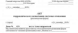
Drawing up a report based on the results of hydrotesting of the pipeline
After checking the pipeline system, a document is drawn up confirming that the tests were carried out in accordance with regulatory documentation and containing a report on the result of the check. The document displays:
- name of the pipeline network;
- name of the inspection company;
- data on pressure indicators during testing and the duration of its implementation;
- data on pressure reduction;
- a list of identified problems or an indication of their absence;
- date of inspection;
- conclusions of the commission.
Briefly about the main thing
A comfortable life is unthinkable without the proper functioning of heating and water supply communications. To determine the readiness of the system for operation, hydraulic tests (pressure testing) are carried out.
During testing, increased pressure is created in the circuit. The amount of increase is calculated in advance based on the pipeline material and system parameters. There are two methods of crimping: precise (instrumental) using pressure gauges and hydrostatic, aimed directly at identifying defects (leaks or deformations).
