Report of hydraulic testing of pressure pipeline
After completion of installation work, pressure pipelines for water supply and, if necessary, sewerage must be tested for strength and tightness. Based on the results of hydraulic tests, a report is drawn up in the form provided by SNiP 3.05.04-85 “External networks and structures of water supply and sewerage.” The full name of the act is an act on conducting an acceptance hydraulic test of the pressure pipeline for strength and tightness. It is worth noting that a report in the above form is drawn up both during preliminary and during acceptance hydraulic testing.
We begin filling out the pipeline hydraulic testing report by entering data about the location of the test (name of the locality), as well as the date of approval of the report. Next, we enter information about the composition of the acceptance committee. The commission should include representatives of the construction and installation organization, technical supervision of the customer, and operating organization. More information about the system of relationships between participants in the construction process can be found here. For each member of the commission, we enter the following data into the act: name of the organization and position, surname and initials of the representative.
At the next stage of filling out the act, we indicate the name of the object (information about the name is found in the project or construction permit), the numbers of pickets on the boundaries of the test site, the length of the site, the diameter and material of pipes and butt joints.
Next, you should fill out the block of the act, which is directly devoted to hydraulic tests. There shouldn't be much difficulty filling it out. We fill out this section in the following order:
1. We indicate the operating pressure of the pipeline (we take information from the project) and test pressure (we take information from the project, or in case of its absence, we calculate it according to tables 4 and 5 from SNiP 3.05.04-85 for tests for tightness and strength, respectively).
2. We enter data on the test pressure gauge into the hydraulic test report. It is necessary to indicate the accuracy class of the pressure gauge, the upper limit of measurements, the scale division value of the pressure gauge, as well as the height of the pressure gauge relative to the axis of the pipeline. In accordance with SNiP 3.05.04-85, only certified pressure gauges with an accuracy class of at least 1.5 with a scale for a nominal pressure of about 4/3 of the test pressure can be used for hydraulic tests.
3. We calculate the readings of pressure gauges for the values of the working and test pressure of the pipeline indicated above in the report. We calculate the readings using the formulas specified in the act.
4. According to Table 6 from SNiP 3.05.04-85, we derive and enter into the hydraulic test report the sample presented on this page, the permissible flow rate of pumped water, first per 1 kilometer of pipeline, and then per length of the tested section.
5. We describe the process of conducting hydraulic strength tests, indicating the previously calculated values of test and operating pressure, the time during which the test pressure was maintained, and the results of inspecting pipelines for ruptures and leaks.
6. We describe the process of conducting hydraulic tests for leaks, indicating the test pressure for leaks, the start and end time of the test, the duration of the test, data on the water level in measuring barrels at the beginning and end of the test, data on the pressure gauge readings on the decrease in pressure in the pipeline at the end testing, the volume of water required to restore the pressure to the test pressure, the amount of water flow pumped into the pipeline during the test. The ΔP value should be taken in accordance with Table 4 from SNiP 3.05.04-85. It should also be noted that the value of the test pressure for tightness Pr should not exceed the value of the acceptance test pressure of the pipeline for strength Pi.
If the flow rate of pumped water does not exceed the permissible flow rate of pumped water for a test section with a length of 1 km or more, which are indicated in Table 6 from SNiP 3.05.04-85, then such a pipeline is recognized as having passed the preliminary and acceptance hydraulic tests for tightness.
Based on the results obtained, the commission makes a decision whether the pipeline has passed the hydraulic tests or not.
After completion of the tests, the hydraulic test report is signed by all members of the commission. Changing the form of the act and deviations from it are not allowed.
Installation, repair and maintenance of boilers and dispensers
Heating system tests
carried out after completion of installation work. But first, all plumbing systems must be flushed.
Before testing, the compliance of the heating system
project, carry out an external inspection of pipelines, connections, equipment, instruments, fittings.
Heating systems are tested
in general and individual types of equipment, and also regulate them. Based on the test results, reports are drawn up.
Testing of heating systems, heat supply
performed by hydrostatic and manometric (pneumatic) methods.
Hydrostatic testing of the heating system
is carried out by filling all elements of the system with water (with complete removal of air), increasing the pressure to test pressure, holding the system under test pressure for a certain time, reducing the pressure and, if necessary, emptying the system. Hydrostatic testing is safe: the system is tested under conditions closest to operating conditions. However, such a test requires water to be supplied to the building to fill the plumbing system, which is unacceptable. If the tightness is broken, flooding of premises and soaking of building structures is possible; In winter, water in the pipes may freeze and “defrost”.
Therefore, hydrostatic testing of heating systems
, heat supply, boilers, water heaters are performed at a positive temperature in the premises of the building. The temperature of the water used to fill the system must not be lower than 278°K (5°C).
Hydrostatic heating tests
carried out before finishing the premises.
Pressure testing of the heating system
In many respects, they do not have the disadvantages of hydrostatic tests, but they are more dangerous, since if pipelines or system elements are accidentally destroyed under the influence of compressed air, their pieces can fall into the people conducting the tests.
Gauge heating tests
carried out by filling
the heating system
with compressed air at a pressure equal to the test one, and maintaining it under this pressure for a certain period, then the pressure is reduced to atmospheric pressure.
For testing, a pneumohydraulic unit TSTM-10 is used in the form of a biaxial trailer, on which a tank with a volume of 2.5 m3 and all testing equipment are mounted.
Heating systems testing
.
Acceptance of heating boiler rooms is carried out on the basis of the results of hydrostatic or pressure testing, and heating systems
- on the basis of the results of hydrostatic and thermal tests, as well as external inspection of installed devices and equipment.
Heating systems
are tested for tightness (but not for strength) by the manometric method under an excess air pressure of 0.15 MPa to detect installation defects by ear and then with a pressure of 0.1 MPa for 5 minutes (in this case, the pressure should not decrease by more than 0. 01 MPa).
Hydrostatic testing of a water heating system
carried out upon completion of its installation and inspection. To do this, fill the system with water and completely remove air from it by opening all air collectors, taps on risers and at heating devices. Fill the system through the return line, connecting it to a permanent or temporary water supply. After filling the system, close all air collectors and turn on a manual or driven hydraulic press, which creates the required pressure.
Water heating systems
are subjected to hydrostatic pressure equal to 1.5 working pressure, but not less than 0.2 MPa at the lowest point. During the test, the boilers and expansion vessel are disconnected from the system. The pressure drop during the test should not exceed 0.02 MPa for 5 minutes. The pressure is monitored with a tested and sealed pressure gauge with scale divisions at 0.01 MPa. Any minor faults found that do not interfere with the hydrostatic test are marked with chalk and then corrected.
A pressure gauge is a device that determines the pressure of liquids and gases. The principle of its operation is based on balancing the action of a gaseous or liquid medium by the deformation force of a membrane or spring. This device is one of the mandatory elements for monitoring the parameters of most engineering communications. Thus, a pressure gauge for a heating system is needed to monitor excess pressure inside the boiler and pipes (see Pressure in the heating system of a private house). At the same time, they are capable of simply informing about the state of the coolant and transmitting a signal that blocks the operation of equipment in order to prevent an emergency.
Components of the heating system pressure test report
At the top left is information about the organization that carried out the inspection. Ideally, there should be a signature for approval by the chief power engineer of the heating supply organization.
The top right should contain subscriber information. That is, about who is the client and consumer of heating services. This could be a partnership of residents of a particular house, any organization that occupies the building, the owner of a private house, etc.
It is important to provide names and other information accurately and in detail. In this case the address is required
The main part of the act states:
- City.
- The date of signing the act (and the pressure test itself).
- Heat supply organization: its form of ownership, name, full name of the representative.
- Which of the subscriber's representatives accepted the heating system after the test: full name, position.
- To what indicators the pressure in the system was raised is indicated in kgf/cm2.
- To what indicators did it drop after 10 minutes following the shutdown (the units of measurement here are also kgf/cm2, it is also permissible to measure it in mPa if accurate data on this matter is available).
- Whether the system passed or failed the test (the person completing the form needs to highlight the correct option).
The final part consists of the signatures and seals (if any) of the representatives:
- Subscriber.
- Heat supply organization.
- Service organization.
In general, the act of pressure testing the heating system is a convenient primary document, for filling out which the heat supply organization is responsible.
Document year: 2019
Type of document: Act
Download formats: DOC, PDF
Test reports are drawn up in the form of document forms in which the results of testing the performance of mechanisms and equipment are recorded.
In today's article, we will consider in detail the testing of pipeline systems, sewerage systems, stairs and stepladders, roof fencing and fire tests.
Examples of drafting acts can be downloaded for free at the end of the article.
Fire test reports
During testing for the performance and safe operation of fire equipment, several reports are drawn up:
- checking fire hydrants;
- diagnostics of internal water supply;
- checking for the safety of use and compliance with labor protection rules of fire escapes.
Fire hydrants
Testing the performance of hydrants for water loss is carried out twice a year and is often combined with checking the fire-fighting water supply system. Based on the results of the inspection, an act is drawn up and signed by the commission. Mandatory members: a representative of the fire inspection and a representative from the organization in which the inspection is taking place. Also, the commission may consist entirely of company employees.
The act states:
- general organizational information (information about the company, date and place of compilation);
- the main part describes the members of the commission and the progress of the test. Information about hydrants is presented in tabular form. The location address, diameter, pressure, water yield and affiliation of the hydrant are indicated;
- in the final part, compliance (or non-compliance) with the requirements of the hydrant condition is established.
At the end, the act is signed by authorized members of the commission.
Internal fire water supply
The act establishes the presence or absence of defects and malfunctions in the fire water supply system. The inspection is carried out by responsible employees of the enterprise. Frequency – at least twice a year; for flammable industries, inspections may be scheduled more often.
Internal fire water supply (IFP) is a complex system of pipes, sensors, and switches. Therefore, it is often checked by a labor protection or fire safety specialist, as well as by persons who are trained in fire safety.
The act is drawn up on letterhead or plain paper indicating the details. Be sure to register:
- information about the organization and participants of the inspection;
- information about the object being checked;
- inspection results;
- recommendations for eliminating defects and malfunctions, if any are found;
- signatures of responsible persons.
If additional documents are attached to the act, their list and name are indicated.
Fire escapes
Testing of firefighting equipment, including ladders and stepladders, is regulated by a special GOST. Inspections can be carried out by organizations that have received permission from the Ministry of Emergency Situations and have special equipment for this.
The test results are recorded in the test report. The documentation provides standard information about the organization and its details, information about the members of the commission. The main part provides information about the inspected objects (number of ladders and stepladders, their inventory numbers and affiliation with the structural unit), information about the results of inspections (absence or presence of defects). An instruction is given to eliminate the identified faults.
At the end, the act is signed by the members of the commission.
Guidelines
A sample of filling out the act is available at the supplying organization. First, the date of testing is indicated. You must enter the name of the object and its address. Here you need to start from the passport of the building. After this, the persons who took part in the work are listed.
The hydraulic test report should be stored carefully
The next point is the area or place where the tests were carried out. Here you need to remember that the full name of the object is indicated.
The process of further filling out the pipeline survey report is as follows:
- Test and working pressure size;
- Time of its fixation;
- Pressure gauge indicators;
- The result of the visual inspection;
- List of repairs carried out or recommended;
- Conclusion about the performance of the system under study;
- Signatures of responsible persons.
A certificate of suitability of the system for further operation is drawn up by the supplying organization or persons who have received the appropriate approval. The regulations for all events are prescribed in SNiP. Strict implementation of all recommendations is a guarantee that the document drawn up will have legal force. Each stage of testing is carefully recorded. All information collected is used to compile the final report.
Pressure test sequence for the heating system
This type of work must be planned in advance and therefore, before carrying out the work, appropriate documentation is drawn up:
- The work order is a permit signed by the responsible person of the organization servicing the heating network.
- A diagram of the sections of the heating main where the test will be carried out, indicating the pressure release points.
- List of employees authorized to conduct tests, including the responsible official.
- A diagram of the location of specialists in the area being inspected, indicating the means of communication between them.
- Description of the testing methodology and processing of the obtained data.
Before starting the pumping equipment, perform a visual inspection of the connections and the condition of the shut-off valves. Also, in order to isolate the heating system from the water supply pipeline, plugs are installed.
Then, according to the procedure, the heating boiler and expansion tank are turned off, and the pipes are flushed to remove deposits and debris no more than once every 4–6 years. This procedure must be performed, otherwise, due to the presence of a thick layer of plaque on the inner surface of the pipeline, its thermal conductivity is significantly reduced. Flushing is carried out in different ways depending on the technical condition of the heating structure.
When carrying out hydropressure testing, the flushed system is filled with water, after which a compressor is connected to the drain valve. The pressure is raised to the required value and the readings on the pressure gauge are observed. When there are no weak points in the pipes, which usually immediately leak, significant pressure fluctuations will not be noticed on the device. If this indicator drops significantly, you should find the location of the leak, which is not difficult to do.
Pneumatic pressure testing is performed using a special pump. To make it easier to find defects at the joints, you need to apply a soap solution to them before testing. The pump is connected to the system and air is forced into the pipes. Subsequent actions are similar to those during hydropressure testing. At the same time, it is necessary to remember to comply with safety precautions.
When breaks or loose connections are detected, the defects should be repaired and then checked again. This procedure is repeated until the system becomes completely sealed.
This is important to know: Tax when inheriting an apartment
Pressure testing is carried out by specialists from organizations that have access, relevant knowledge and skills. They must be able to follow the sequence of work activities while ensuring safety. Finally, fill out the heating system pressure test form.
When the work is carried out
All activities related to checking heating for leaks are carried out in the following cases:
- During preparation for the heating season;
- When replacing sections of the circuit;
- After repair of heating devices;
- When putting the property into operation.
The test procedure itself is a confirmation of the tightness of the circuit
.
This procedure includes the following components:
- Supplying air or water with a given pressure into heating pipelines using special equipment;
- Finding deformations in the heating circuit;
- Elimination of violations.
It is worth noting that modern heating schemes allow such events to be carried out with a minimum number of personnel.
Pipe crimping
As you can easily guess from the title of the article, its topic will be pipe crimping - what crimping is, why it is done and what tools are needed for it.
Crimping: a concept in a broad sense
The very concept of “pressure testing” in relation to metal-plastic hoses should be considered in the broad sense of the word. For example, pressure testing often refers to standard tests carried out hydraulically or pneumatically.
But modern practice shows that the term “pressure testing” also quite logically fits the procedure for connecting a fitting and a metal-plastic pipe. This type of connection is made using power crimping technology using a special tool (press pliers).
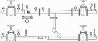
The photo shows the moment of crimping during the process of joining metal-plastic pipes. In this case, crimping is a mechanical force action aimed at achieving tightness of a reliable connection
Regardless of the installation conditions and the technologies used, the installation of water supply or other communications based on metal-plastic pipes is accompanied by tests for tightness and strength.
This is approximately what the connection point for a pressure testing pump to a water supply system on metal-plastic pipes looks like. One of two control pressure gauges is installed at the inlet, which determines the tightness of the circuit
Typically, the testing process is carried out hydraulically. But the possibility of testing using the pneumatic method is not excluded.
Conclusion
: Pressure testing of the heating main - let's look at the main thing
Introduction. up
The purpose of this article is to describe the procedures for pressure testing (pressure testing) of installed pipes and connections of the heating and water supply system to check the quality of the work performed.
The general principles of the hydrostatic (water pressure testing) and manometric (air pressure testing) methods are described.
Specific recommendations from leading manufacturers of polymer pipelines, which are often used in the installation of heating and water supply in private homes, are considered: Uponor, Rehau, Herz, Kan. Sets out local codes and regulations regarding pressure testing.
What is pressure testing of pipelines and connections. up
After installing pipelines and connections of elements of heating and water supply systems, it is necessary to check the quality of installation work and make sure there is no damage or poorly installed elements.
Such tests must be carried out before and immediately during the embedding of elements of engineering systems into the building structures (pouring floor screeds, plastering grooves, sewing niches, etc.).
This procedure allows you to promptly notice and eliminate accidental damage, reducing the likelihood of the so-called manifestation. "human factor".
A self-tapping screw accidentally screwed into a pipe laid in the wall or a sharp nail on a shoe when pouring heated floor pipes, or a pipe damaged during transportation or installation can (and often does) go unnoticed if pressure testing has not been carried out. During commissioning, these damages still make themselves felt and require expensive repairs, incl.
and to restore the fine finishing of the premises (replacing tiles, plastering, puttying, painting, wallpapering, etc.).
Pressure testing of pipes can be carried out either with water (the working medium - which is preferable) or, in some cases, with air. Checking pipelines with air is most often carried out when the ambient temperature drops below +5°C and there is a risk of water pipes freezing.
The methods for testing heating and water supply systems with water (hydrostatic tests) and air (manometric tests) are somewhat different (see below).
The test pressure should be selected based on the test medium (water or air), the operating pressure of the piping system, the pipe manufacturer's recommendations, and local codes.
Conclusion
I think we have fully answered the question of what pipe crimping is and why it is needed. The choice of a specific tool is up to you. Good luck!
Useful technical details
Chemical
Chemical flushing involves filling the heating circuit with reagents (alkali or acid solution with inhibitors that prevent further corrosion of pipelines) and long-term circulation of the reagent in the circuit.
Used reagents are generally disposed of by the contractor. You cannot pour them into the sewer: such aggressive substances can sharply shorten its service life, and wastewater treatment plants are not designed for the disposal of acids and alkalis.
If it is necessary to use the sewer system for disposal, the reagents are first neutralized. Acidic - alkali solutions and vice versa.
Hydropneumatic
This type of flushing is the most common, cheapest and most versatile. However, it is associated with the consumption of a significant amount of water. If the house is connected to a heating main, the coolant coming from it is usually used; Autonomous heating systems are washed with cold water.
The actual washing is done like this:
- The heating system starts to reset - first from the supply to the return, then in the opposite direction.
- A stream of compressed air from the compressor is mixed through the valve into the flow of water coming from the route. The resulting pulp effectively washes away silt and, partly, deposits on the pipe walls.
- With a standing heating system, groups of risers are blocked in turn so that the entire flow of pulp goes through no more than 10 risers. Less is better.
Washing of each group of risers in each direction is carried out until the moment when the pulp going for discharge becomes transparent.
The hydropneumatic flushing pump is a simple and relatively inexpensive device.
Stages of testing
Activities consist of preparation, direct testing and analysis of indicators obtained as a result of tests.
- The first stage is preparation. During this period, the initial data on the network is clarified and recorded, after which the measurement program is developed and agreed upon. At this stage, preparatory actions are also underway to create testing conditions. This includes: Before starting the process, you need to check whether all work on welding, installation, installation of gaskets in connections, and tightening of these connections has been completed.
- You also need to check whether all the equipment is in order, the presence and functionality of the air drain valves.
- Connecting the hydraulic press to the water supply and to the pressure pipe pipeline. Checking the correct connections.
- Disconnecting the pipeline section where the test will be carried out from equipment that has not yet been fully installed or is already in use.
- Installation of necessary instruments for testing.
The second stage is to conduct a test under appropriate conditions. Tests must be carried out in compliance with all requirements regarding ambient temperature conditions. In case of violation, this may lead to inaccuracy of the received data. The necessary conditions:
- The ambient temperature during events must be above zero.
- The temperature of the water used in the test should be from +5 to +40.
- Providing observation platforms for above-ground heating systems.
- Smooth increase in pressure. It should be approximately 40% higher than nominal. To increase it, the use of compressed air is prohibited.
- The test section of the pipeline must be maintained under test pressure for at least 15 minutes.
- Upon completion, the entire site must be carefully inspected and if defects are found, the measures necessary to eliminate them must be taken.
And the last stage is to analyze the results obtained and compile a table indicating all the parameters. If deviations from the norm are detected, measures are taken to eliminate them, such as:
- Cleaning and flushing of the pipeline.
- Pipeline relocation.
- In case of serious problems, repairs and elimination of detected defects are carried out.
Upon completion of measures to eliminate the causes of deviations, the tests must be carried out again.
1. Requirements for the site and workplace when testing with portable equipment
3.1.1. The area for hydraulic testing must comply with the requirements of the current sanitary standards for the design of industrial enterprises CH118, CH119, CH245, building codes and regulations SNiP2, SNiP8, SNiP9.
hydraulic stand (or portable equipment when tested on an assembly stand);
auxiliary equipment and accessories;
of the tested product, taking into account the safe performance of work on its installation and inspection, while the free zone around the perimeter of the maximum possible size of the product must be at least 1 m.
3.1.3. The area must have a non-slip floor covering with a slope and (or) holes for water drainage, as well as a protective fence that excludes the possibility of unauthorized persons accidentally appearing on the area and the penetration of working fluid outside the area (Appendix).
There should be a light sign on the fence with the inscription “NO ENTRY. TESTS ARE IN PROGRESS” or a corresponding poster.
3.1.4. The site must have general and local working lighting, emergency lighting, as well as portable lamps with a voltage of no more than 42 V. Lighting equipment must comply with the requirements "".
The lighting should provide illumination on the surface of the product being tested:
working - at least 300 lux with fluorescent or 200 lux with incandescent lighting;
emergency - at least 10 from the working one.
3.1.5. The hydrotesting site must have a circulating water supply system that ensures the volume of the tested products is filled or a technical water supply system with a drainage system into the sewer system.
Hydraulic tests
General information
Based on the Rules for the Technical Operation of Thermal Power Installations (approved by Order of the Ministry of Energy of the Russian Federation dated March 24, 2003 N 115), when operating heating network systems, heating network enterprises must ensure the reliability of heat supply to consumers, the supply of coolants (water and steam) with flow rates and parameters in accordance with temperature control schedule and inlet pressure drop.
During operation, all existing heating networks must be tested for strength and density to identify defects no later than two weeks after the end of the heating season.
Hydraulic testing of pipelines of water heating networks in order to check strength and density should be carried out by test pressure with the results entered into the report.
Test pressure is the excess pressure at which hydraulic testing of thermal power plants and networks for strength and density should be carried out.
The minimum value of test pressure during hydraulic testing is 1.25 working pressure, but not less than 0.2 MPa (2 kgf/cm2).
The maximum value of the test pressure is established by strength calculations according to the normative and technical documentation agreed with the State Mining and Technical Supervision Authority of Russia. The test pressure value is selected by the manufacturer (design organization) within the range between the minimum and maximum values.
Hydraulic tests are carried out by the person responsible for the safe operation of heating networks together with personnel authorized to operate heating networks.
Hydraulic tests
When conducting hydraulic tests for the strength and density of heating networks, the equipment of the heating networks (stuffing box, bellows compensators, etc.), as well as sections of pipelines and connected heat-consuming power plants not involved in the tests, should be disconnected with plugs.
Strength and density tests are carried out in the following order:
disconnect the tested section of the pipeline from existing networks;
at the highest point of the section of the pipeline under test (after filling it with water and bleeding air), set the test pressure (control using a pressure gauge);
the pressure in the pipeline should be increased gradually;
the rate of pressure rise must be indicated in the regulatory and technical documentation (NTD) for the pipeline.
Tests for strength and density are carried out in compliance with the following basic requirements: pressure measurements during testing should be carried out using two certified spring pressure gauges (one control) of class not lower than 1.5 with a body diameter of at least 160 mm. The pressure gauge must be selected from the condition that the measured pressure value is within 2/3 of the instrument scale; test pressure must be provided at the top point (mark) of the pipelines; the water temperature must be no lower than 5 °C and no higher than 40 °C; when filling with water, air must be completely removed from the pipelines; the test pressure must be maintained for at least 10 minutes and then reduced to working pressure; at operating pressure, a thorough inspection of pipelines is carried out along their entire length.
The test results are considered satisfactory if during the test there was no drop in pressure and no signs of rupture, leakage or fogging were found in the welds, as well as leaks in the base metal, in valve bodies and seals, in flange connections and other pipeline elements. In addition, there should be no signs of movement or deformation of pipelines and fixed supports.
A report of the established form is drawn up on the results of testing pipelines for strength and density.
document
Download as .doc/.pdf Save this document in a convenient format.
It's free. Appendix 5 to Methodological recommendations for technical inspection of pipelines of heating networks of public heating systems
ACT FOR HYDRAULIC TESTING OF HEATING NETWORK PIPELINE DURING TECHNICAL INSPECTION (recommended form) ________________ "__" ____________ Object ___________________________________________________________ We, the undersigned _____________________________________________________ (name of organization (enterprise) ___________________________________________________________________ position, full name) have drawn up this act in that , that in the section from chamber N ______________ to chamber N ______________ of route ________________________________ (name of pipeline), a hydraulic test of the pipeline was carried out with test pressure _____________ MPa (kgf/sq. cm) for ________ minutes. followed by inspection at a pressure of __________ MPa (kgf/sq. cm). At the same time, it was discovered that ___________________________________________________ ___________________________________________________________________ The pipeline was made according to the design ___________________________________ Drawings N __________________________________________________________ Conclusion ________________________________________________________________ ___________________________________________________________________ ___________________________________________________________________ The person who carried out the technical examination (the person responsible for the good condition and safe operation of the pipeline); representative of the State Supervision Authority; representative of a third-party organization ___________________________________ (full name, position) Representative of an organization operating heating networks ___________________________________ (full name, position)
Download as .doc/.pdfSave this document now. It will come in handy.
You found what you were looking for?
* By clicking on one of these buttons, you help form a rating of the usefulness of documents. Thank you!
Related documents
- Act: samples (Full list of documents)
- Search for the phrase “Act” throughout the site
- “Act for hydraulic testing of a heating network pipeline during a technical examination (recommended form).”doc
Documents that may also interest you:
- An act for documents, valuables and money found at the scene of an aircraft accident. Form N 5
- Act on delayed departure of aircraft
- Certificate for cleaning the pile (trench, vegetable storage). Specialized form N 14-OT
- Act on changing the quality of products. Specialized intradepartmental form N LP-7
- An act for the removal of components and parts containing precious metals from medical and other equipment products. Form N 42-MT
- Act on the exclusion of a universal container from the inventory belonging to the railway administration
- Act on geodetic, topographical and cartographic objects and works completed, accepted by the technical control department and handed over to the Fund by the enterprise
- Act on personal belongings, valuables, documents and awards of a deceased (deceased) serviceman of the civil defense forces (a serviceman or an employee of the state fire service of the Ministry of Emergency Situations of Russia, a citizen called up for military training, and a person discharged from military service (service))
- Act on personal belongings, valuables, documents and awards of a deceased (deceased) serviceman
- Act on personal belongings, valuables, documents and state (departmental) awards of a deceased (deceased) serviceman, citizen called up for military training
Test program for heating points
The work program for testing heating substations is developed by the contractor conducting the tests, based on the design and operational documentation of all units of the heating substation. The work program should include:
- Safety Procedures
- Measures for preparing test equipment
- Test procedure
- Technical description of measuring equipment
- Test timing
- Test Responsible
The contractor coordinates this package of documents with the customer and then all actions are carried out according to the approved plan. After testing, the results are analyzed, on the basis of which a test report and technical recommendations for operation and repair are drawn up (if “weak points” are identified). If violations were identified during the tests, then after eliminating them, the tests must be repeated.
The engineering department of Rusenergo LLC provides customers with a detailed technical report based on the results of hydraulic and thermal tests of heating points. The report evaluates the condition of the heating point equipment, indicates measurement standards for the following tests and inspections, recommendations for repair work and technical requirements for the operation of all components of the heating point. If during testing our specialists discover ineffective operation of individual components, erroneous connection diagrams or outdated components, the technical report will provide full recommendations for the renovation of the heating unit.