Mounting options
To ensure reliable and safe operation of the valve in the heating system, it is recommended that installation be carried out in accordance with all rules. You can find them in special regulatory documentation. The rules differ depending on the power and operating pressure of the system. But the basic principles still remain, including:
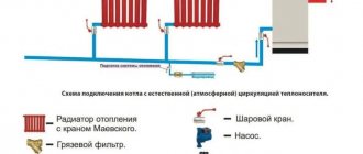
- In a heating system, this device must be installed on the supply pipe directly after the boiler. If the generator is large, it is possible to install two valves.
- The safety valve on the return pipe of heating systems is installed only to ensure hot water supply at the highest point of the boiler.
- It is also unacceptable to narrow the channel in places between the main line and the valve, and the installation of shut-off valves is unacceptable.
- Discharge pipes should be discharged into a sewer system or other safe place. The installation of shut-off devices on this line is completely unacceptable.
Calculation
The calculation of the safety device must be carried out in accordance with the methodology presented in SNiP II-35 “Boiler installations”.
Since manufacturers rarely indicate the actual height of the rod lift in the technical specifications, in the calculation this parameter is equal to 1/20 of the seat diameter. For this reason, the valve size as a result of this calculation is somewhat overestimated. In any case, after selecting a device, it is necessary to compare the thermal power of the heating system with the maximum power recommended in the technical description for the selected standard size.
Installation of a safety valve is required to protect the heating system from exceeding the pressure level above the maximum permissible value. For this reason, the calculation of this device should be reduced to calculating the maximum permissible increase in coolant volume and identifying possible sources of excess pressure.
Sources of volume growth can be:
- Overheating in a heat exchange or boiler unit with subsequent vaporization. When vaporizing, a liquid can increase its volume by 461 times, so this factor is the predominant factor when choosing a valve.
- Failure of automatic control of make-up lines of boiler houses and independent heating systems. This may also be a predominant factor in valve selection.
- The coolant, heating up in a heat exchange or boiler unit, increases in volume. When heated, the specific volume increase is from 0 to 100 °C, which is only 4%, so when selecting the size of a device of this type, this is not a fundamental point.
The selected equipment must ensure the discharge of the calculated amount of coolant, according to the most significant factor in the increase in volume.
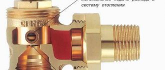
Safety valve in the heating system device diagram
This device consists of a housing and two cast elements. The body is made of plumbing brass, manufactured using hot stamping technology. The main component of the valve is a steel spring. Using its elasticity, it establishes a pressure force that will act on the membrane blocking the passage to the outside.
In turn, the membrane, located in a seat equipped with a seal, is pressed by a spring. The upper part of the spring rests against a metal washer mounted on the rod and screwed to the plastic handle. The handle is required for the heating system.
Let's take a closer look at the types of these devices.
Thermal valve
It is considered the most effective control valve for heating radiators. This device increases the practicality of the circuit and makes the heating process simple, good, and most importantly, healthy. The thermal valve can be mechanical or automated. Products of the first type consist of thermal and valve.
Automated models have a more complex design; they consist of these elements:
- temperature sensor - built-in or remote;
- programmer;
- automatic control systems.
An automated type mechanism is designed to regulate the temperature regime in the circuit in accordance with the settings that are pre-set by heat energy consumers. This device is sold at a high price, but it is fully justified, because with its help you can maximize the functioning of the heat supply system.
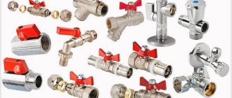
Types of valves
They are determined by the type of locking device and are as follows:
Poppet valves are an active element, a disk that sits on a seat with a seal, blocking the working section. The plate is attached from the inside to a rod that can move freely in the body.
A conical or cylindrical spring is installed between the body and the disc element, ensuring a tight fit of the disc to the seal. When the direction of pressure changes, the disk compresses the spring, and the flow resumes in the desired direction.
Gravity valves - the operating element is a petal loosely attached to one hinge. Under normal conditions, the petal is held in the open position by the flow of water; when the flow direction changes, the locking element closes the hole under gravity. The stronger the counterflow pressure, the tighter it is pressed against the body.
Ball (float) check valve is an analogue of a poppet check valve, with the difference that the role of a locking device is played by a ball. It is usually made from light aluminum-based alloys or rubber.
The ball can move along the inclined channel under the lid with normal water flow. When the direction changes, the spring presses the ball against the saddle and the coolant flow stops.
The petal mechanism locks the channel with a soft spring, which lowers the petal onto the seat with a sealing cuff. In principle, such a valve can operate without a spring under the influence of gravity on the leaf and under the influence of the dynamic pressure of the return flow.
In this case, it is held in the open position by the force of the coolant flow in the right direction. Hydraulic resistance to flow is minimal and does not change its dynamic characteristics.
Take note:
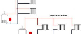
double-leaf mechanisms are used in large cross-section pipelines and for systems with high water pressure. The principle of operation is the same - the pressure of the flow opens the doors. When the pressure drops, the flaps close.
The peculiarity of this design is that these products can only be used in a horizontal position.
Features of installing a balancing valve
Installation of balancing valves for the heating system is necessary if you notice irregularities in the distribution of heat across the radiators of different rooms. Balancing fittings are also installed in new buildings where they are provided for by the design. Installation is carried out in compliance with the following features of the device:
- The fittings are inserted into the pipe taking into account the direction of flow, which is indicated on the body.
- Automatic models are sensitive to water contaminants, so a filter is placed in front of the device.
- It is necessary to exclude the influence of turbulence on the operation of the valves. It is enough to leave a straight section of pipe in front of the valve, then the water flow will move without turbulence, and the operation of the device will be more correct.
Before installation, it is necessary to flush the pipe and check its integrity. Installation of a balancing valve for heating consists of the following steps:
- Select a piece of pipe suitable for inserting the valve. For stable operation, it will be enough if the straight section in front of the valve is five pipe diameters, after which two or three diameters will be enough.
Procedure after installing the valve Source ytimg.com
- The device is screwed into the pipe; For sealing, flax fiber with lubricant is laid in advance. The minimum number of threads is seven.
- The tap is screwed onto the pipe at one end, and the other is connected to the battery, observing the direction of coolant flow. Spatial placement does not affect the work; it can be anything.
Device specifics
The design of automatic and manual heating drain valves has one common detail. We are talking about a channel (valve) that is intended to remove accumulated air. Automatic devices are equipped with a float: when it is in the upper position, this indicates that the needle valve is closed.
After the gas appears, the float lowers. As a result, the rocker opens the valve and air begins to flow out. After removing the air plug, the float rises, which allows the needle to close the valve. As a result, the system returns to its normal operating mode.
Mixing taps
Mixing taps are located in front of the heating ring. With their help, the heating in the system is adjusted. When you turn the handle of the three-way tap, it opens, the pump draws in cold water, after which it is mixed with the hot coolant in the system. Thanks to this device, the operating principle of faucets - mixers regulates the water temperature.
The safety valve is installed both on the coolant supply pipeline and at the heated water outlet if heating is carried out using hot water.
When installing a safety valve in a heating system, the following conditions must be met:
Safety valve installation rules
- Absence of foreign devices in the valve-pipeline system;
- The diameter of the control valve is larger than the diameter of the pipe;
- Use of a special safe room for the removal of discharge pipes;
- The selection of the required diameter must be carried out by specially trained people using the relevant approved regulatory documents;
- The pressure difference between the valve and the installation should be between 15 and 25%.
- Carrying out mandatory regular checks of the operation of safety devices. The check is carried out during their forced opening. Recommended verification of devices should be carried out at least once a year. Preferably before applying heat.
These are large diameter pipes. Equalize the pressure in the pipeline. Such a collector is installed in a special distribution heating cabinet.
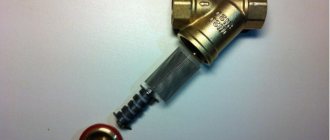
To remove sludge from the system, ball valves embedded in the manifolds are used. In addition to ball valves, the installations use magnetic dirt removers. The dirt removers have a special mesh arranged in the form of a fan. Thanks to this design of protection, various kinds of particles and small debris found in the water are retained, separated and discharged into a designated collection tank.
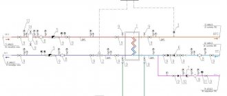
Distribution collectors and slurry collectors
The manifold is a larger diameter pipe, which is designed to equalize the pressure in the pipes. The manifold is placed in the heating distribution cabinet.
Distributing collectors
To remove sludge, ball valves are installed into the collectors for heating. There are also special devices for this – deslimers. Inside they have mesh surfaces that are arranged like a fan. The sludge that is in the water collides with them, is separated and falls to the bottom of the body and is then taken to a special place.
Back
The device serves to prevent a change in the direction of fluid movement in the circuit. The essence of the fuse is simple. A special locking mechanism allows water to flow in only one direction - into the heating tank. In addition, when the pressure in the pipelines increases, excess water is discharged through the “spout” of the valve. To prevent water from spilling onto the floor, it is recommended to put a discharge pipe on the outlet of the valve and drain it into the sewer.
Spring loaded
In spring-loaded check devices, the through-hole flap is closed using the clamping force of a spring. The flow of water presses on the membrane, lifting the spring and opening the passage hole. In the case of a return flow of liquid, which is unacceptable if a closed heating circuit is used, the spring presses on the membrane from above, closing the hole. Pressure from the reverse side further increases the downforce, preventing a change in the direction of flow.
Ball
It is based on the same principle, but instead of a spring and a shutter, a steel ball is used that closes the drain hole under the influence of gravity. This imposes some restrictions. For example, it can only be used on horizontal heating areas.
Heating safety valves
In addition to the heating bypass valve, the normal operation of the system requires the installation of other types of control and safety valves. During heating operation, excess air may appear and the coolant will move back. To prevent these phenomena, it is necessary to provide in advance the installation of an air valve for heating and return.
Depending on the functional purpose, there are two types of safety valves - to remove air from the system and to prevent the reverse movement of water in the pipes. Without these elements, the operation of the system may be unstable, which will lead to a violation of the temperature regime, destabilization of pressure and the creation of emergency situations.
- In places with the highest probability of excess pressure - after boilers, circulation pumps, on collectors;
- A petal equivalent must be mounted on the return pipe. It is also necessary to install this component in the circulation pump piping;
- At the highest point of the circuit - to remove air from the system. A Mayevsky tap is installed on radiators and batteries.
Safety valves must not impair the performance of the heating system. First of all, they eliminate possible malfunctions in the heat supply. In the “inactive” state, these system components should not impair the speed of movement of the coolant or affect the temperature regime.
Heating air valve
During heating operation, air pockets may form in pipes and radiators. The reason for this is the high oxygen content in the water and the coolant temperature above +100°C. As a result, oxidation of metal components occurs and the temperature distribution changes. To avoid these situations, it is necessary to install valves to bleed air from the heating system.
First of all, the air valve for heat supply is mounted in the safety group along with the drain and pressure gauge. In the heating circuit they are located on a straight branch leading from the boiler. This place has the highest coolant temperature, as well as maximum pressure. In the manifold circuit, it is mandatory to install heat supply drain valves on each comb.
- Mayevsky crane
. Installed in the radiator (battery) and needed to remove air pockets; - Automatic air vent
. Mounted at the highest point of the system, as well as in security groups. Air from the heating system escapes through it.
For the latest model, it is important to comply with the operating conditions. After a long period of inactivity, there is a high probability that some moving components will “stick” and then the air vent will not work.
To avoid this, the structure should be regularly inspected and, if necessary, replaced with a new one.
Heating check valve
Without a circulation pump, there is always the possibility of a change in the direction of water movement. In this case, the boiler heat exchanger may be damaged due to overheating, as well as failure of other components. To prevent such situations, a check valve is installed.
In large heating circuits, a heat supply ball valve is installed. Under the influence of the reverse flow of water, the polymer ball blocks the pipeline, thereby preventing the movement of the coolant. As soon as the direction changes, it falls down under the influence of gravity. The solenoid valve for the heating system works on the same principle. The difference lies in the control element - a solenoid or an electromagnetic coil is used for this.
The advantages of installing a solenoid valve in a heating system are as follows:
- Possibility of connection to the programmer;
- Setting the operation mode of the device depending on external factors - temperature or pressure;
- Reliability of operation.
The disadvantage of solenoid valves in heat supply is their dependence on the supply of electricity. In autonomous heating, a spring version of the check valve is used. The water pressure constantly acts on the saddle, compressing the spring. As soon as the direction changes, the movement of the coolant will be automatically blocked.
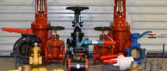
Shut-off valves
In heating systems, shut-off valves for heating are used to control the supply of coolant, as well as to open the circuit.
It allows you to control the heating process, making it more efficient and rational. In most cases, the shut-off valve on the heating radiator is installed in the radiator piping areas. In addition to functional advantages, this solution also has practical benefits - by closing the shut-off valve for the heating radiator, the homeowner will be able to repair the heating device without stopping the operation of the entire heating system. At the moment, shut-off valves for heating are represented by a wide range of devices. The following types of devices are often used in heating systems:
- shut-off valves;
- Ball Valves;
- needle valve;
- valves
These elements are made of durable metals that are resistant to corrosion and high temperatures. Shut-off valves protect the circuit from critical emergencies and increase the reliability of the heating system, helping to minimize the negative consequences of failure of an individual heating device.
Ball Valves
A ball valve is a shut-off valve for heating radiators, which is installed to regulate the flow of coolant. The design of the fittings includes a union nut, an internal thread, a plug and an air release device designed to bleed air from the system. When choosing this type of fittings, you need to pay attention to the material from which the valve is made and the presence of o-rings, which increase the service life of the element in the circuit. Brass taps have proven themselves well, as they are characterized by increased wear resistance and corrosion resistance.
Shut-off valves
This type of fittings is used to make it possible to replace radiators without draining the coolant from the circuit. Based on their design features, there are angle and straight shut-off valves. Moreover, some models can be equipped with a release mechanism to smoothly reduce the pressure in the circuit. Shut-off valves are characterized by a hose nozzle - it allows installation of the device as quickly and simply as possible.
Needle tap
The functions performed by a needle tap for heating can be different. Depending on the design, this device can perform locking, regulating and balancing functions. In heating systems, a shut-off needle valve for the heating radiator is most often used, which allows you to smoothly shut off the flow and avoid the occurrence of water hammer, which is detrimental to the system. Unlike a ball valve, which has two operating positions, a needle valve can operate in three positions:
- "closed";
- "open";
- "partially closed".
Valves
This type of valve performs exclusively a shut-off function. Due to its design features, it can operate in two modes - the mechanism is equipped with a locking element located perpendicular to the coolant flow. In the open position, the valve supplies coolant to the circuit, and in the closed position it prevents its circulation. Among the features of the valve, it is worth noting the low hydraulic resistance created in the circuit, the optimal diameter of the internal section, which coincides with the diameter of the pipeline, simple installation and high reliability.
Overview of thermostats
Heating regulators include a valve and a thermocouple. The heat transfer is regulated using the valve. The operating principle is based on the distribution of water flow, which depends on the external temperature. The valve includes a spool, the height of which determines the flow capacity. Depending on the height, movements can be low-lift or full-lift.
Low-lift ones have a height of 0.05. For full lift - more than 0.25. The first type of thermostats is recommended for use where there is a small throughput (usually a liquid medium), the second type is most suitable for a gaseous medium.
In addition, valves can be spring and lever-load. In lever-loaders, the spool is combined with a lever. A load is hung on the lever. Thanks to the movement of the load, which is carried out along the entire length, the force of pressing the spool against the seat is adjusted.
When a difference occurs between the pressures of the medium and the lever, an automatic opening occurs and the flow of coolant into the discharge pipe is ensured.
In addition to the safety element, bypass and check valves are used, with the help of which the pressure in the heating system is also regulated. The principle of operation of these devices is similar to the principle of operation of the safety element. The only difference is that they are connected to the return line. They ensure the movement of water into the return pipeline when the pressure exceeds the permissible level.
The main parameters that must be taken into account when choosing these devices are the operating pressure. Their job is to pass water in one direction and exclude movement in the opposite direction.
Bypass valve
How to balance a radiator network
Typically, installers of heating systems set the coolant flow rate on the batteries in a simple way: they divide the number of revolutions of the balancing valve by the number of heating devices and in this way calculate the adjustment step. Moving from the last radiator to the first, close the taps with the resulting difference in speed.
Example. On one “arm” of the dead-end system we have 5 radiators with Oventrop manual valves with 4.5 spindle turns. Divide 4.5 by 5, we get an adjustment step of about 0.9 turns. This means that we open the penultimate heating device by 3.6 turns, the third by 2.7, the second by 1.8, and the first by 0.9 turns.
The method is quite approximate and does not take into account the different power of batteries, and therefore can be used as a preliminary setting with adjustments during operation.
A contact thermometer that measures the surface temperature of pipes and radiators will help you balance your heating more accurately.
Our experienced expert Vladimir Sukhorukov offers another technique based on measuring the actual surface temperature of heaters. The step-by-step balancing instructions look like this:
- Open all balancing valves as much as possible and put the system into operating mode with a supply temperature of 80 °C.
- Use a contact thermometer to measure the temperature of all heating devices.
- Eliminate the resulting difference by tightening the taps of the first and middle radiators; do not touch the end ones. Open the near battery by 1-1.5 turns of the valve, the middle ones by 2-2.5.
- Allow the system to adapt to the new settings for 20 minutes and repeat the measurements. Your task is to achieve a minimum temperature difference between the battery farthest and closest to the boiler.
Note. The weather and outside temperature do not matter, only the difference in the heating of the radiators is important. By the way, in normal operating mode at 50-70 °C at the supply temperature delta will become even lower. How the system is hydraulically balanced using balancing valves, watch the video from an expert:
Safety valve in the heating system selection
The diameter of the valve inlet pipe must be equal to or greater than the diameter of the pipe obtained in the calculation. In addition to matching the diameter of the pipe, it is necessary to check the safety device for releasing the calculated increase in coolant volume in the event of an emergency
It is also important to take into account the fact that the greater the pressure difference between the values in the relief line and when the valve opens, the greater the amount of liquid will be released through the safety equipment
When selecting this device, you should also remember that its full opening is achieved when the pressure in the heating system exceeds the response value by 10%, and full closure is achieved when the pressure drops below the response value by 20%. Based on this, it is advisable to select equipment with a response pressure higher by approximately 20-30% of the actual system pressure.
(no votes yet)