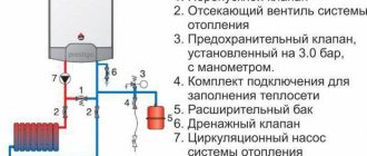
Shut-off valves for pipelines are designed to regulate the flow of liquid moving through a pipe - turn it off, start it up and redirect it. We will understand the features of these parts, the specifics of their operation within the pipeline system, the classification and differences between one group of devices and another, and also study the main properties, selection parameters and operating rules during installation work.
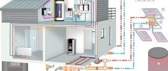
Shut-off valves are an important component of the water supply system Source sgrupp.ru
Types of shut-off and control valves
To begin with, let’s make a reservation that in this topic we are considering only elements of heating circuits of private houses and apartments, since in the general case the range of fittings used is quite wide. It will be difficult to review it within one article.
Types of heating taps
So, shut-off and control valves are elements of a system designed to control the flow of coolant by partially or completely blocking the flow area of pipelines.
By and large, all flow control elements installed in heating systems of private houses can be divided into the following groups:
- constipation;
- shut-off and regulating;
- mixing and regulating.
You should not confuse concepts such as shut-off and control valves and control and measuring instruments (thermometers, pressure gauges). Also, various safety and air vent valves, filters - mud traps and metering devices have nothing to do with the control of the coolant.
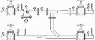
Balancing valve
During the installation of heating systems, it is used to regulate the operation of several hydraulic circuits. Installing a balancing valve makes it possible to increase the efficiency of the heating structure, as it helps control the possible volume of coolant consumed.
Properly installed, this type of fittings, whose operating principle is to distribute the heated liquid evenly across all segments of the heat supply system, can work in very difficult conditions. This device can withstand significant pressure drops in the circuits and high speeds of movement of the coolant through pipelines.
The balancing valve, the price of which for direct-acting modifications is not small, consists of the following important elements:
- housing made of steel, aluminum alloy or brass;
- pipe section;
- position lock;
- membrane septum;
- measuring diaphragm;
- shutter indicator.
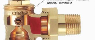
Shut-off valves
The most common example of a shut-off device is a simple ball valve. It has only 2 working positions: “open” or “closed”. Due to its design, when open, the valve allows a flow of liquid through itself without changing its direction or flow area. It is a brass body with a built-in element in the form of a ball with a hole, rotating a rod with a handle, as shown in the diagram:
Section of shut-off valves
The polished steel ball is sealed with polymer material and can rotate 90º. As can be seen from the diagram, the design of the control valves also allows the flow to be blocked not completely, but this method of control is not used. Firstly, it is too rough, and secondly, the hole of the ball, rotated at some angle, creates high hydraulic resistance to the flow of liquid.
Stopcock with filter
For reference. Modern ball valves are produced in multifunctional versions: with a built-in drain fitting, a Mayevsky valve, a strainer and even an electric drive. In addition, there are three-way ball valves that can switch flows in different directions. The last 2 modifications are used in individual systems quite rarely.
Three way valve
In water heating systems, shut-off ball valves are used in the following places:
- cutting off radiators from the system for the purpose of their periodic maintenance;
- to disconnect branches and risers;
- shutting off the flow to remove or repair heating and pumping equipment, expansion tanks;
- for emptying and refilling the system.
Electric crane
Shut-off devices also include check valves and various shut-off valves with electric drive. It should be noted that in systems of private houses and apartments, shut-off and control valves with an electric drive are very rarely installed, unless in complex and branched circuits controlled by automation.
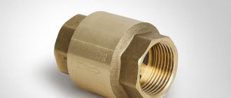
Valve
As for check valves, their task is to pass the coolant in full in one direction, and to tightly shut it off in the other. Place of installation of elements - boiler piping diagrams and other special cases when it is necessary to avoid the reverse movement of water.
Ball valves
This product refers to shut-off valves for devices for heating a room. It is designed to regulate the flow of liquid, which is used as a coolant. A valve with a round hole consists of a union nut, an air release device, which is designed to bleed air from the system, and a plug. The product has an internal thread.
When purchasing this type of fittings, you need to look at the material of manufacture and the presence of o-rings that increase the service life of this element in the circuit. As practice shows, brass taps themselves are distinguished by their very high wear resistance and anti-corrosion resistance.
Shut-off and control elements of systems
These include the following devices:
- balancing valves;
- automatic differential pressure regulators;
- thermostatic radiator valves.
Balancing valve
The listed types of shut-off and control valves are designed to carry out quantitative regulation of the coolant. That is, by partially blocking the flow section of the pipeline, these elements provide a certain flow of water entering a section of the system or into a heating device. Balancing valves are installed both at the outlet of the batteries and at the beginning of a branch or riser of the system, as a rule, on the return line.
Valve diagram
With a large number of batteries, the disposition may change and the installation of shut-off and control valves is carried out using automatic differential pressure regulators. They are placed together with valves and connected to them by a capillary tube. The balance valve provides the required coolant flow to the branch or riser, and the regulator adjusts it in accordance with the operation of the radiator thermostats.
Application of automatic valve
Automatic thermostatic valves are fittings for radiators that reduce or increase the flow of hot water through the radiator depending on the room temperature.
Valves with thermal heads
It is installed on the supply line and can be additionally equipped with a thermal head and a remote thermostat for more precise control of coolant flow. It is considered an integral element of modern schemes and one of the main means of saving energy.
Thermostatic valve
Additional heating devices
These primarily include thermometers and pressure gauges. They are necessary to control the condition of hot water. By default, such devices are installed in the heating boiler. But in addition to this, their installation in critical areas of the system is necessary. This applies to control fittings for heating a warm water floor (collector unit). The pressure gauge must be present in the safety group along with the air vent.
For each valve for heating systems, shut-off or control, the main performance indicators are often indicated on the body - the maximum (minimum) level of pressure and temperature. How can you choose the optimal model even without having a passport for it?
As an example, you can familiarize yourself with the range of shut-off valves from Valtec:
Mixing and control valves
A prominent representative of this group of devices is the thermostatic three-way valve. Its task is high-quality regulation of the coolant, that is, by temperature, and not by flow. A three-way valve does not act like a shut-off valve, it works like a mixing unit. Configured to produce coolant at a certain temperature, the element mixes the two flows in the required proportions.
Heating mixing unit
The device is a brass body with three pipes, inside of which there is a rod controlled by a thermostatic drive. The rod passes through 2 seats, regulating the flow of the required amount of water through them from two pipes, in order to obtain a mixture of the set temperature in the third.
Operating principle of three-way valve
It must be said that not every heating system needs such fittings. The scope of application of mixing devices is maintaining the temperature in underfloor heating circuits, individual radiators or entire groups of heating devices, as well as in small circulation circuits of solid fuel boilers. In general, it is quite difficult to list all the special cases of using mixing valves, since there can be a lot of them in modern water heating schemes.
Needle valves
The functions that a needle tap must perform are distinguished by their diversity. According to the structural device, such a product usually has a shut-off, regulating and balancing purpose.
The needle valve in heating systems is used for heating devices. Due to its presence, a smooth shut-off of the flow is ensured and it is possible to avoid the consequences of water hammer, which have a negative impact on the entire heat supply structure.
Unlike a ball valve, which has two positions, a needle valve can operate in three modes:
These fittings perform exclusively a locking function. Due to the design features of the valve, it is usually located exclusively in two positions, since the mechanism has a closing component located perpendicular to the flow of the coolant. If the valve component is in an open position, the heated liquid enters the circuit, and when it is closed, it does not allow it to circulate.
The valve has a number of special characteristics:
- Provides low hydraulic resistance in the circuit.
- It has a suitable diameter size inside, similar to the cross-section of the pipeline.
- It's easy to install.
- It stands out for its great reliability.
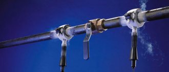
Shutters: practice of use
Gates are the most important part of shut-off valves of any type. It is thanks to the serviceability of the valve that timely and complete (or, if necessary, partial) blocking of the movement of liquid or gas flow in the pipeline is possible.
Accordingly, if the valve is faulty or poorly manufactured, the consequences can be anything - from a minor, harmless leak, eliminated by simply replacing structural elements, to a full-fledged environmental disaster or explosion of the carrier
Therefore, special attention is paid to the material used to make the valves and their operating conditions. The most common type of valves is butterfly valves.
They are used in heating systems, water supply, steam supply, non-aggressive working environments or petroleum products. Flange valves are also used, the distinctive feature of which is the presence of a flange in the design.
The most common type of valve is a butterfly valve. They are used in heating systems, water supply, steam supply, non-aggressive working environments or petroleum products. Flange valves are also used, the distinctive feature of which is the presence of a flange in the design.
Gates can be made of cast iron, but the use of steel products (alloy, stainless or carbon steel) is preferable.
Steel valves have a number of significant advantages:
- operation at temperatures down to -60°C is possible;
- such valves can operate in environments with temperatures up to 700°C;
- designed for use in aggressive working environments;
- withstand high pressure (up to 10 MPa).
How rotary shutter mechanisms differ:
- ease of installation and repair;
- compactness (they can be mounted in confined spaces);
- small, compared to gate valves, weight and dimensions;
- ease of replacement when the product wears out and has a long shelf life;
- low price;
- no risk of jamming or sticking during use.
Therefore, the selection, quality and installation of shut-off valves should be approached as responsibly as possible, basing your decisions not only on the price of the product or country of origin, but also on pre-made calculations. And, of course, we must not forget about timely maintenance and scheduled replacement of elements that are so important for any pipeline.
Bypass valve
This type of control devices is used to normalize the difference in pressure between the supply and return pipes. The use of a bypass valve in heating systems in which thermal valves are connected to the circuits is considered mandatory, since they create pressure differences in specific areas and thereby reduce the efficiency of heating.
Shut-off control valves for heating devices and heating circuits on the market today are provided with a large selection of valves of any design. It is necessary to purchase certain devices in accordance with the design documentation for the improvement of the heating system, which is calculated and created for a specific home or building, depending on its purpose.
This approach can be explained by the fact that different types of pipes and heating devices are installed in each building. Taking them into account, the choice of fittings is made.
Main advantages of valves:
- comparative simplicity of design, low hydraulic resistance;
- relatively short construction length;
- the symmetry of the valve allows the working flow to pass in any direction;
- possibility of use in various operating conditions, high tightness;
- well-free installation, long service life under adverse conditions;
- the ability to repair and replace components when they break or wear out;
- low torque when controlling an electric drive;
Number of sections of bimetallic radiators
How many sections there will be on a bimetallic radiator has a direct impact on the choice of connection method. A battery of up to 8 sections can be connected with a side, bottom saddle or diagonal connection. If there are more than 8 sections, it is better to use a diagonal connection.
When using side switching, a flow extender will be required. This refers to a tube inserted into the supply manifold. It helps out in situations where the side connection provides heating only for the first sections. Thanks to the tube inserted inside, the coolant flows further than the inlet, heating the surface of the device more evenly.
Flow extension length options:
- 2/3 batteries.
- To the center of the last section.
Different cases show the effectiveness of both the first and second options. The main thing is that a noticeable optimization of radiator heating is achieved. Sometimes it happens that installation to the middle of the last section provokes a decrease in the heating level of the first sections. In this case, it is recommended to shorten the tube. But such situations rarely occur, which is influenced by the pressure in the riser and the cross-section of the liner.
Non-rising stem valves:
In valves with a non-rising stem
the running thread is located inside the valve cavity and when opened, the spindle does not move out of the cover, maintaining its original height position. The running nut in these valves is connected to the shutter and, when the spindle rotates to open the passage, it seems to be screwed onto it, dragging the shutter along with it. In valves with a non-retractable spindle, the running assembly is immersed in the working environment and is therefore susceptible to corrosion and abrasive particles in the working environment, access to it is closed and there is no possibility of maintenance during operation, which leads to a decrease in the reliability of the running and stuffing box units.
In this regard, such valves have limited use - for pipelines transporting mineral oils, oil, water, which are not clogged with solid impurities and do not have corrosive properties. Since valves with a non-rising spindle make it difficult to observe and maintain the running gear, they are not recommended for critical facilities. The advantage of this design is the lower construction height, which makes it advisable to use them for underground communications, wells, oil wells, etc.
Rising stem valves:
In rising stem
The spindle thread and the running nut are located outside the valve body. The lower end of the spindle is connected to the shutter and when the running nut is rotated to open the valve, it makes only translational movement together with the shutter, while the upper end of the spindle extends by the amount of stroke of the shutter. To allow movement of the spindle, the running nut is raised above the top of the cover (that is, above the stuffing box) by approximately the amount of stroke of the shutter in a design called a yoke assembly.
The advantages of this design are the absence of harmful effects of the working environment on the running unit and free access for its maintenance, and therefore less wear of the gland seal and higher reliability of the threaded pair and gland. The disadvantage of such valves is the increase in construction height and weight due to the spindle coming out of the cover by no less than the diameter of the passage, and for this reason, during installation, it is necessary to leave free space for the spindle to come out.