When setting the goal for an intra-house or apartment heating system to function efficiently, its actual thermal parameters must be extremely close to the calculated values. This can be achieved if the coolant is distributed correctly across the heating circuits, while maintaining stable pressure and temperature parameters.
This problem is especially relevant in developed heating systems that heat objects with a large heating area. To perform this task, a specialized device is integrated into the system - a balancing valve.
What is a balancing valve
To maintain an equal temperature in the radiators, the volume of coolant passing through the device is regulated; the smaller it is, the lower the heat transfer from the battery. In practice, it is possible to regulate the flow using a conventional ball valve, and this is effective if the number of heating elements in the circuit does not exceed one. Otherwise, it is not possible to set the same temperature in different batteries using a ball valve.
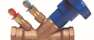
Balancing valve
Balancing valve for heating system effectively maintains heat balance by applying automatic or manual adjustment in heating elements. Structurally, this is carried out through a special mechanism that partially closes the passage of the coolant, just like any shut-off and control device, but with the difference that the required volume of the balancer is set manually or automatically using preset adjustment scales.
The balancing valve is installed on the return pipeline. This approach makes it possible to guarantee a constant rate of water circulation in the batteries, even if a common line is used for heating and the DHW circuit. If the balancing scheme provides for the installation of balancers at each radiator, then they are placed at the bottom of the radiator outlet fitting, diagonally with respect to the coolant supply ball valve located in the upper part of the heating device.
Application options
In private homes, mechanical models are often used. They are quite enough to heat a building with an area of up to 500 m². Installation of manual main valves is carried out in the following situations:
- in buildings with an extensive heating system with many risers;
- in multi-apartment buildings equipped with an individual boiler room;
- when connecting a solid fuel boiler with an existing heat accumulator.
Radiator models are installed at the outlet of the heater, while main valves are installed exclusively in the pipeline that returns the cooled liquid to the boiler room. If the structure is mounted in conjunction with an automatic valve, then it can be located in both the return and supply pipelines.
Steel and aluminum radiators with bottom connections are often initially equipped with taps using specialized fittings that serve as attachment of connections to such parts. The need to install valves also disappears in the following cases:
- in dead-end mechanisms of insignificant length, with identical hydraulic “shoulders”;
- when all batteries have preset thermostatic valves;
- on the final radiator (dead-end);
- in collector plan mechanisms.
Temperature regulators with presetting, mounted on the liquid supply, also cope with the operation of the balance valve, which is why a shut-off ball valve can be attached to the outlet of the heating mechanism. In a similar way, the fittings are installed on the connections to the last battery in the chain, and since there is no need for adjustment, it should be completely open.
The principle of operation of the balancer in the heating system
Operating principle of the balancer
The principle of operation of the balancing device is that the valve seat is capable of changing the internal passage. Rotating the handle sets the corresponding nut and spindle in motion. When unscrewing, the valve rises to the upper operating position, which ensures maximum fluid flow; when tightening, the spindle presses on the valve seat, lowering it to the lower position, thereby reliably blocking the passage of fluid through the radiator.
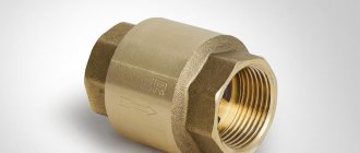
The radiator modification, used for mechanical adjustment of the thermal and hydraulic modes of the heating circuits, is made of the following elements:
- The body is made of brass with threaded pipes for installation of intra-house pipelines.
- Molded round seat located inside the body.
- A device for adjusting the cross-section of the coolant passage is a regulating spindle, which rests against the saddle when screwed.
- Rubber sealing ring.
- Protective and safety cap made of metal/plastic.
Design
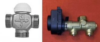
Control valves vary in design. In the classic version, the device is equipped with a straight rod and a flat spool; adjustment occurs by changing the flow area between the spool and the seat. The forward movement of the spool is ensured by rotation of the handle.
Balancers are also available with a rod located at an angle relative to the coolant flow; the spool can have a cone-shaped, radial or cylindrical shape, and is driven by a servo drive.
Balancing valve design
Functional features of a balancing valve for a heating system
Main balancing valve
The automatic balancing valve for the heating system for the main network differs from the radiator design in dimensions, spindle angle and fitting geometry.
Automatic balancer functions:
- Drainage of water from the heating system;
- connecting sensors to measure coolant parameters;
- installation of a pulse volute tube from a pressure corrector.
The number of turns that the balancer is capable of performing is from 3 to 5; this figure varies among most manufacturers. In order to change the position of the rod, you will need a wrench with a hexagon configuration. The adjustment is carried out based on the pressure difference in the heating network. During the setup process, when the flow rate of circulating water changes, the pressure loss in the pipeline and control valve also changes, which in turn leads to a change in the differential on the balancer.
The pressure drop in the network can be determined independently from the readings of pressure gauges installed on the return/supply of the in-house heating system. For example, with a supply/return pressure of 2.5 / 2.0 bar, the difference will be 2.5 – 2.0 = 0.5 bar. When the valve is automatic, it sets the differential itself according to the algorithm established by the design.
It should also be noted that not all heat supply systems require balancing. For example, if there are up to three short dead-end branches in the in-house wiring, equipped with 2 devices on each, their operation can be configured using ball valves or conventional shut-off and control valves.
Methods and procedures for balancing
There are two main methods to balance heating devices
:
- Simple. It is also the most labor-intensive. When adjusting the position of the balancing valves, their readings are taken multiple times.
- Difficult. It is reliable because it involves dividing the system into modules (individual heating devices or a group of them). Each module is equipped with a balancing valve, ensuring its autonomy. The total power of the heating system is taken as 100%, and the readings of individual parts are converted into fractions (20%, 40%, and so on). Next, each module is adjusted separately until the indicator corresponds to the desired value.
Measuring the readings of the balancing valve
This is also convenient in terms of operation, when the temperature range can be easily changed if necessary. The number of balancing valves can be increased gradually, starting with one device in the area of the circulation pump.
Types of valves and their design features
All new heating systems using radiator thermostats are considered dynamic. During operation, the thermostat installed on the heating device responds to any slight changes in the temperature conditions inside the room, thus changing the flow of heating water.
This creates a changing or dynamic operating mode in the heating system. It is a prerequisite for the introduction of automatic/dynamic balancing devices.
Classification of balancing valves by parameters:
- Type of coolant working medium: water, steam-water mixture, glycol composition;
- standard coolant parameters for volume flow, T and pressure;
- location points on the heating network: supply, return or bypass;
- purpose and number of floors of the heating facility; residential/public, single-story/multi-story;
- working function: automatic/mechanical.
- Their combination according to connection options is also practiced: threaded or flanged.
A variety of materials can be used to release valves. Static valves are most often made of brass, with a flanged/threaded connection, or cast iron, exclusively with a flanged connection. For dynamic modifications, in addition to brass/cast iron, they also use carbon steel, which is capable of providing the highest quality standard thermal and hydraulic characteristics of the system.
Manual balancers are required in order to adapt the heating network after installation, and automatic balancers change the characteristics of the heating network during the heating period.
When choosing a balancer modification, it is necessary to take into account various parameters:
- Type of heating circuit with natural/forced circulation.
- Thermal and hydraulic parameters of the network.
- installation point in the in-house system.
- adjustment parameters.
Mechanical balancer
Mechanical balancer
The mechanical valve has manual adjustment and works perfectly in a stable heating network. Works well for residential properties with not a very large number of heating devices. It facilitates repair and adjustment work, since when repairing a separate heating section there is no need to turn off the entire system.
Such modifications are very often equipped with measuring nipples capable of measuring the pressure in the system in the area where the valve is located. The main advantage of such regulators is their low price.
Mechanical balancer - the device works effectively in those facilities where the number of radiators is no more than 5 units. With more, the mechanics cannot cope and causes an imbalance in the heat supply circuit. When the thermostat on the 1st battery is closed, the coolant flow on the second increases. Due to this, the temperature of the water in some heating devices may rise to the boiling point, while in others it will remain cold. Only automatic balancers can solve this problem.
Automatic balancer
Automatic balancer
Installation of automatic units is carried out on branches/risers with a significant number of batteries. They differ from mechanical devices in the order of their operation. The balancer is adjusted to the position of the greatest throughput. When the hot water flow rate decreases by the thermostat on one of the batteries, the pressure increases. Then the impulse tube mechanism is activated, which analyzes the magnitude of the pressure drop. This approach allows for fine-tuning of the network.
The main advantages of automatic equalizers:
- The presence of a capillary tube that facilitates instant adjustment;
- the control unit does not change the pressure during operation, thereby preventing hydraulic vibrations in the network from disrupting the set mode;
- if necessary, special temperature independent zones can be installed in the general network;
- the high speed of adjustment of the balancer does not allow thermostats to rearrange their operation, which guarantees balanced operation of the entire intra-house heating system.
What is the difference between a balancing valve and a regular tap?
Unlike conventional shut-off and control valves, a balancing valve, thanks to the combined action of a membrane and a spring, responds to pressure changes occurring in the installation. It maintains the pressure drop in the dead-end zones of the circuit in accordance with the set value. This regulation is ideal for heating devices that constantly operate at a balanced flow of heating fluid.
This level of control of hydrodynamic modes increases the efficiency of the heating network and reduces the cost of heating services and cannot be ensured by using only conventional ball valves.
The difference between the operation of a balancing valve and standard valves:
- Reduces the cost of operating pumping equipment for coolant circulation.
- Maintains temperature difference - delta T. Pressure independent valves providing the calculated coolant flow through the radiator for full or part load situations. Consequently, the calculated delta T value will be achieved, resulting in increased efficiency of the heat sources or heat exchangers.
- Balances the circulating flow, measures pressure drops in operating condition and blocks violations of the specified hydraulic mode through the radiator.
- Adjusting the flow of heating water depending on the purpose of the objects brings a significant economic effect due to low specific fuel consumption.
- Setting minimum gas flow rates and maintaining a constant temperature in all rooms, including during periods of temporary absence of residents.
Purpose of the device
All branches of the heating system must receive the calculated amount of coolant. Previously, simple systems were controlled by using pipes of different diameters. In complex ones, special washers were installed, by moving which it was possible to change the cross-section of the pipeline. Today, a special valve is used that operates on the principle of a valve.
The balancing valve is equipped with two fittings, thanks to which
:
- the pressure of the coolant flow is measured before and after passing through the valve;
- a capillary tube is connected to allow adjustment.
Based on the readings of the device, it is possible to determine the pressure drop when water passes through the regulator, and calculate, according to the instructions, how many turns of the handle are required to optimize the operation of the heating system.
Note! A number of manufacturers offer balancing valves with a digital display, but such devices are more expensive.
Cross-section of balancing valve
Types and installation schemes of balancing valves
Placing balancing valves in the intra-house heating network helps to achieve fine adjustment of the temperature inside the rooms depending on their purpose - in residential rooms it is set higher, and in auxiliary rooms - lower. This motivator increases the comfort of both an apartment and an individual house.
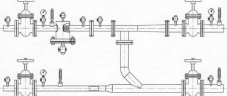
Installation diagrams
In order to understand the principle of operation and rules for the location of the balancing valve, you need to consider two standard heating schemes:
- From the boiler unit there are 4 heating circuits with different lengths and different numbers of batteries from 3 to 8.
Setting up a system with thermal heads - Also, the heating circuit is only equipped with thermostats.
Setting up a system without thermostatic valves
Since the coolant always passes along a path with minimal hydraulic resistance, in the 1st scheme, a significant part of the thermal energy will be acquired by the first batteries along the flow of water, and those located at the very end of the supply line will receive either a minimal amount of heat or not receive it at all. In practice, situations quite often occur when the temperature difference between these points is 10 degrees or more.
In order to provide heat to remote radiators, balancing valves are installed on the connections to the nearest heating devices from the boiler unit. By partially blocking the passage for the coolant, they reduce the water flow, thus increasing the hydraulic resistance of the above section. Using a similar method, the feed is adjusted in systems where there are five or more dead-end lines.
In the second option, the situation is much more complicated. Installing thermostats on batteries makes it possible to automatically change the volume of water. On remote lines of a heating network with a large number of heating devices equipped with thermostats, balancers are connected to automatic regulators that control the pressure drop.
With the support of a capillary tube, they are connected to the balancer, thereby responding to a decrease/increase in the flow of heating water in the system and, holding the specified medium pressure in the return line. Consequently, the heat will be evenly distributed throughout all rooms, despite the activation of thermostats.
Modifications and manufacturers
Today, the distribution network has a sufficient supply of modern balancing valves, both domestic and foreign. The latter have more functionality and significant cost. The development of the market for such equipment is caused by the EU requirement for the introduction of energy efficient technologies. By the way, it will be said, but in EU countries it is prohibited to put into operation heating systems that are not equipped with valves of this modification.
List and prices of popular models of balancing valves:
- CIM 790, DN15, manufacturer Italy Cimberio, protection against pressure and water hammer, 4500 rub.
- VIR Du15-50, device from Italy, manual type, brass manufacturing with preliminary adjustment and subsequent fixation, 6525 rub.
- USV-I Du 25, manufactured by Danfoss Denmark, with an operating temperature range from -20 to 120 C, RUB 2,768.
- Tadano TR100M-1, produced in Japan, from 15,000 to 100,000 rubles.
- DN 50-300 mm KBCh, produced in Moscow, made of cast iron with a working environment temperature of up to 120 C, from 3460 to 130140 rubles.
- Herz Shtremax-M Du20 (3/4″) Ru10, produced in Austria, brass, temperature up to 110 C, 2561 rub.
Why do you carry out hydraulic adjustment of CO?
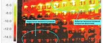
The main goal of balancing the heating system is the correct distribution of the amount of coolant to the radiators (batteries) per unit of time, directing the required amount of heat to places where there is a shortage.
For a more complete understanding of the picture, imagine that in a certain area of the CO it is divided into two circuits, each of which leads to different rooms. Since the volume of the rooms is different, the length of the contour may vary. A circuit with a longer length (or more heating devices) has more hydraulic resistance. As you know, water (coolant) always follows the path of least resistance. In other words, according to physical laws, more heat will enter a shorter circuit than distant radiators. The figure clearly shows the distribution of thermal energy in two identical systems.
We should not forget that in an untuned CO the heat generator operates at maximum, which negatively affects all structural elements.
Summarizing the above, CO balancing is carried out for:
- Uniform heating of batteries, regardless of their location in the heating system.
- Economical operation of the boiler installation.
Advice! Balancing a two-pipe heating system (carried out with preliminary hydraulic calculations), of small length (no more than 4 heating devices) is optional
.
In all other cases, for efficient and economical operation of the CO, hydraulic adjustment is necessary!
How to adjust the balancing valve in a heating system
Setting up a mechanical balancer
Before setting up the balance of the radiator network, you need to study the instructions for the valve, which are included when purchasing it. It indicates an adjustment scheme; if the user installs everything correctly, he can actually reduce the cost of thermal energy. The valve can be adjusted in two ways.
The first way to adjust the valve
This is the simplest and most proven adjustment option, which is recommended by experienced thermal regulators in water heating networks. To do this, you will need to divide the number of valve revolutions by the number of batteries installed in the heating circuit around the perimeter of the room. This technique makes it possible to correctly determine the step of the tuning algorithm. The method consists of closing all the valves in the reverse order - from the outermost to the first battery in relation to the heating source.
For example, for a dead-end circuit with 4 radiators equipped with mechanical balancing valves and a 4.5-turn spindle adjustment:
4.5:4 = 1.1 turns
Opening diagram:
- The first balancing valve is 1.1 turns.
- Second balancing valve – 2.2 turns.
- Third balancing valve – 3.3 turns.
- The fourth balancing valve is 4.5 turns.
The second way to configure the balancer
There is another, very high-quality method of balancing. It runs much faster, and contains the ability to take into account some of the specific location of the battery. The only thing you need to do this is a contact thermometer.
The complete process goes like this:
- Open all the valves and allow the network to enter temperature equilibrium with the operating temperature, for example, 80 C.
- Measure the temperature of all heating devices.
- Eliminate the difference by shutting off the first and middle taps. The end valves are not adjustable.
- Typically, the first valve turns no more than 1.5 revs, and the middle ones - 2.5 revs.
- Allow the system to reach temperature equilibrium for 20 minutes
- Temperatures are measured and valves are adjusted further if necessary.
How to balance a radiator network
To balance a simple radiator network circuit, such valves are not needed. Regulation occurs using thermostats. Balancing valves are necessary if the system has 2 or more branches with several radiators in each. This is relevant for heating systems of apartment buildings, industrial or commercial premises. For such schemes, it is recommended to install automatic models.
Adjustment procedure.
- Calculate the number of balancers in the circuit.
- Adjustment step – from larger value to smaller value
- Calculated based on the number of valves. Let's assume that the numerical calculated value on the first one is 5.0 with a total number of balancers - 6. This means that the next one needs to be reduced by 0.83 to 4.17. On the third it will be 3.33, etc.
- After starting the heating, check the actual pressure and temperature values for each radiator branch.
During operation, the hydraulic balance may change. For manual models, adjustments need to be made once every 2-3 months, for automatic models - once a year. Preventive inspections are required before each heating season.
The use of balancing valves for a specific heating system is determined at the design stage. An exception is that during heating operation it is impossible to adjust the balance using standard means. The solution is to install balancers and recheck the system.
The video shows an example of an installation diagram for such shut-off and control valves:
Views: 353