- The selection of the optimal thermal operating conditions of heat pipelines and the development of effective thermal insulation structures are carried out on the basis of thermal calculations.
- The task of thermal calculation includes solving the following issues:
- 1) determination of heat losses of a heat pipeline;
2) calculation of the temperature field around the heat pipe, i.e.
determination of temperatures of insulation, air in the channel, channel walls, soil;
- 3) calculation of the coolant temperature drop along the heat pipeline;
- 4) selection of the thickness of the thermal insulation of the heat pipe.
- To determine the heat loss of heat pipelines, it is necessary to calculate the total heat transfer resistance
from the wall of an uninsulated pipeline through the thermal insulation layer to the outside air. - Let's consider the thermal calculation of a heating pipeline laid in a non-passable channel.
If there is an air gap between the insulated pipeline and the channel wall, the thermal resistance of the heat pipeline is determined as the sum of series-connected resistances (Fig. 9.2):
R = Ri + Rn + Rp.k + Rk + Rgr
, (9.4)
where Ri, Rn, Rp.k, Rk, Rgr
– resistance, respectively, of the insulation layer, the outer surface of the insulation, the inner surface of the channel, the walls of the channel, and the soil.
Rice. 9.2. Scheme of a single-pipe heat pipeline in a channel
The values of thermal resistances are determined in accordance with the basic provisions of the course “Heat and Mass Transfer”.
The task of thermal calculation of a multipipe heat pipeline in a channel comes down, first of all, to finding the air temperature in the channel.
Knowing the air temperature in the channel, it is possible to determine the heat loss of each pipeline according to the general rules for thermal calculation of pipelines surrounded by air.
The air temperature in the channel is determined by the heat balance equation.
In a steady thermal state, the amount of heat supplied from the pipelines to the air gap of the channel is equal to the amount of heat removed from the air gap through the walls of the channel and the soil mass into the environment.
As a result of solving the heat balance equation, we obtain the expression for the air temperature in the channel:
here and are the coolant temperatures in the supply and return lines; — soil temperature.
Specific heat losses, W/m
, insulated pipeline are equal to:
The heat loss values calculated using equation (9.6) are compared with standard heat loss (Appendix 8). If the calculated heat losses do not exceed the standard ones, then the developed thermal insulation design is effective.
The decrease in coolant temperature along the heat pipeline is determined from the heat balance equation:
where is coolant flow, kg/s
;
— heat capacity of the coolant, ; and are the coolant temperatures at the beginning and end of the section, ; — length of the route, m
;
— specific linear heat losses, W/m
.
From equation (9.7) we find:
. (9.8)
Task 7. Calculate the heat loss of two heat pipes laid in a non-passable channel.
The following are specified: pipeline diameters, insulation thicknesses and, coolant temperatures and.
Internal channel dimensions: width H
, height
h,
wall thickness
b,
base and ceiling.
Depth of pipeline axis; heat transfer coefficient inside the channel; thermal conductivity coefficients: insulation; soil; channel walls; soil temperature on the channel axis; .
The initial data for thermal calculation of heat pipelines are given in table. 9.1.
Table 9.1.
Numerical data for task 7
| Last digit of the cipher | Heat wire diameter | Insulation thickness, mm | Channel dimensions, mm | The penultimate digit of the cipher | Coolant temperature, | Depth of the axis of heat conductors, m | |||
| 1 | 57 3 | 80 | 40 | 600 | 450 | 1 | 150 | 70 | 1,2 |
| 2 | 76 3 | 80 | 40 | 600 | 450 | 2 | 125 | 70 | 1,4 |
| 3 | 89 3 | 90 | 50 | 600 | 450 | 3 | 135 | 70 | 1,6 |
| 4 | 108 4 | 90 | 50 | 900 | 450 | 4 | 140 | 70 | 2,0 |
| 5 | 133 4 | 100 | 60 | 900 | 450 | 5 | 145 | 70 | 1,8 |
| 6 | 159 4,5 | 100 | 60 | 900 | 450 | 6 | 130 | 70 | 1,3 |
| 7 | 194 5,0 | 100 | 60 | 1200 | 600 | 7 | 135 | 70 | 1,5 |
| 8 | 219 6 | 100 | 60 | 1200 | 600 | 8 | 140 | 70 | 1,7 |
| 9 | 273 7 | 100 | 60 | 1200 | 600 | 9 | 125 | 70 | 1,9 |
| 0 | 325 8 | 100 | 60 | 1500 | 900 | 0 | 130 | 70 | 1,4 |
Example solution for task 7
Initial data . Specified: 2 insulated heat pipes
laid in a non-passable channel (Fig. 9.3).
- 100 mm; 60 mm; ; ; 700 ; ; ; ; .
- Define: and .
Rice. 9.3. Scheme of a two-pipe heat pipeline in a channel
- Calculation procedure
- I. Heat supply line
- 1. Determine thermal resistances:
- - insulation
- ;
- — heat transfer from the insulation surface to the channel air:
- ;
- — heat transfer from the channel air to its wall:
- ,
- where the internal equivalent diameter of the channel is:
- — channel walls:
- where is the outer equivalent diameter of the channel:
- - soil:
- ,
- where is the equivalent soil diameter
- (here is the heat transfer coefficient from the ground to the outside air).
- II. Return heat pipe
- 1. Determine thermal resistances:
- ;
- .
- III. We find the thermal resistance of heat transfer:
- — supply pipeline
- — return pipeline
- -channel
IV. We determine the air temperature in the channel using formula (9.5):
.
V. Find the heat loss of pipelines using formula (9.6):
- - server:
- - reverse:
- Control questions:
1. Describe the main tasks of thermal calculation of heat pipelines.
2. Give the dependence of thermal resistance on the outer diameter of the heat-insulating shell of the heat pipe.
3. Outline the methodology for calculating the air temperature in a non-passing channel of a heating main with two heat pipes.
4. What is the method for calculating the heat loss of a two-pipe heat pipeline laid in a non-passage channel?
10. STEAM HEATING SYSTEMS
Like water steam heating systems, there are single-pipe, two-pipe and multi-pipe
(Fig. 10.1).
The most widespread are two-pipe
steam systems with condensate return to the heat source (Fig. 10.1,
b
). Condensate from individual local heat consumption systems is collected in a common tank located at the heating point, and then pumped to the heat source.
Steam condensate is a valuable product: it does not contain hardness salts and dissolved aggressive gases and allows you to save up to 15% of the heat contained in the steam. The preparation of new portions of feed water for steam boilers usually requires significant costs, exceeding the costs of condensate return.
The question of the feasibility of returning condensate to the heat source is decided in each specific case on the basis of technical and economic calculations.
Multi-pipe
steam systems (Fig. 10.1,
c
) are used on industrial sites when receiving steam from thermal power plants and in cases where the production technology requires steam at different pressures.
The costs of constructing separate steam pipelines for steam of different pressures turn out to be less than the cost of excess fuel consumption at a thermal power plant when supplying steam of only one, the highest pressure, and subsequent reduction of it to subscribers who need lower pressure steam.
Condensate return in three-pipe systems is carried out through one common condensate pipeline.
- At large industrial sites that unite several enterprises, complex water and steam systems are built to supply steam for the technology and water for heating and ventilation needs.
- At subscriber inputs of systems, in addition to devices that ensure heat transfer to local heat consumption systems, the system for collecting condensate and returning it to the heat source is also of great importance.
- The steam arriving at the user input usually enters the distribution comb, from where it is directed directly or through a pressure reducing valve (pressure automatic device “after itself”) to the heat-using devices.
Condensate collection schemes are open
and
closed.
The simplest
open
condensate collection scheme is shown in Fig. 10.2. According to this scheme, condensate from heat-using apparatus 2 passes through condensate drain 3, i.e.
the device allows liquid to pass through and does not allow steam to pass through, and enters the condensate collection tank 4, which communicates with the atmosphere through a special pipe 1.
From the tank, condensate is pumped by pump 5 to a heat source or, in the case of a single-pipe system, sent for use by the consumer.
Fig. 10.1. Schematic diagrams of steam heat supply systems
- a - single-pipe without condensate return; b - two-pipe with condensate return; c - three-pipe with condensate return; 1 - heat source; 2 - steam line; 3 — subscriber input; 4 — ventilation heater; 5 - heat exchanger of the local heating system; 6 - heat exchanger of the local hot water supply system; 7 - technological apparatus; 8 — condensate drain; 9 - drainage; 10 — condensate collection tank; 11—condensate pump; 12 - check valve; 13 - condensate line
- The disadvantages of an open condensate collection scheme are:
- a) the danger of condensate absorbing oxygen from the air, which causes corrosion of condensate lines;
- b) losses of secondary boiling steam and heat lost with steam into the atmosphere.
Calculation of heat losses in heating networks - Better heating
Calculation of heat losses from pipelines of heating networks is carried out on the basis of the methodology given in SNiP 2.04.14 Thermal insulation of equipment and pipelines.
The method for calculating heat losses is suitable for all pipelines that are subject to these standards, with the exception of systems with a negative temperature of the working environment.
Calculation of the magnitude of heat losses was carried out based on the standard heat flux density through the insulated surface of the pipeline. The methodology uses tabular data on specific heat losses per meter of pipe given in SNiP. Heat losses for pipe diameters and coolant temperatures not listed in the tables are determined by interpolation and extrapolation methods.
Estimated heat losses by pipelines of the heating network are determined by the formula:
q
– the specific standard value of heat losses per meter of pipe, W/m, at the average temperature of the coolant and a given number of operating hours per year, is determined for each diameter according to the tabular data of SNiP 2.04.14;
k
– the coefficient taking into account additional heat losses from pipeline supports and fittings is taken from tabular data;
b
– coefficient taking into account the change in heat flux density through the heat-insulating layer of polyurethane foam (PPU), determined according to SNiP 2.04.14;
l
– length of the pipeline section, m.
Coolant temperature
To calculate heat losses in heating networks, the following should be taken:
- average coolant temperature per year - for continuously operating networks;
- average coolant temperature for a period with an average daily outside air temperature below 8°C - for heating networks operating only during the heating season.
The design temperatures in two-pipe water heating networks with high-quality regulation, depending on the temperature schedule of heat supply, are used:
Calculation of heat losses from pipelines - Heating networks The program for calculating heat losses from pipelines of a Heating network is based on the methodology given in SNiP 2.04.14 Thermal insulation ...
Source: www.ktto.com.ua
Let's look at an example of calculating heat loss.
Losses in heating networks Qtc for the reporting period are determined as the sum of heat losses with unproductive leakage of water from the network Qt, with productive leakage Qt.pr, and heat losses through insulation in the pipelines of the heating network from the interface to the thermal energy metering unit Qiz.
The value of productive leakage is determined in accordance with the relevant acts.
According to the “Balance Demarcation Scheme”, the “Consumer” has on its balance sheet a section of the heating network from the point of connection - thermal chamber TK-2 to house No. 4 with a nominal diameter of DN65, length - 118.2 linear meters.
Gasket type: through channel.
Let us determine the standard values of average annual heat losses for this heating network using the formula:
- β is a coefficient that takes into account local heat losses, losses of supports, fittings, and compensators. Determined according to SNiP 2.04.07 - 86. For our case β = 1.2;
- L is the length of the pipeline (section of the heating network);
- qн = qп + qз - standard values of specific heat losses of two-pipe water heating networks when laid in a through channel and the number of operating hours per year is less than 5000;
- 1 kcal/h = 1.163 W.
According to the temperature chart in heating networks 105°С - 70°С, we accept the average annual temperatures of the coolant (water) in water heating networks:
Average annual water temperature in the pipeline system:
Heat energy losses through pipeline insulation
This calculation displays standard loss values that should not be exceeded if pipeline insulation was selected in accordance with SNiP. Actual values may differ from standard values.
If pipelines are insulated with IZOVOL or other modern insulating materials, heat loss through the insulation will be very low.
To accurately calculate losses, it is necessary to use a method based on an algorithm for calculating the passage of heat through a cylindrical wall.
For a Du65 section with a length of 118.2 running meters:
qn=(29+17)/1.163=39.66 Kcal/m h (SNiP 2.04.14–88, Appendix 4, Table 4);
We calculate the normalized values of monthly heat losses through pipeline insulation for a heating network:
- n is the duration of network operation in a given month, hour;
- Qn avg - Gcal/h.
Calculation of heat losses in heating networks during the transportation of thermal energy. Thermal energy losses through pipeline insulation. This calculation displays the standard values of losses that should not be exceeded if the pipeline insulation was selected in accordance with SNiP.
Source: teplokom.com.ua
Hello, friends! Calculation of heat losses by heating pipelines is an important and necessary calculation, as it allows you to determine in numbers the amount of heat lost in heating pipes.
This calculation is also important for the reason that heat supply organizations include heat losses through pipelines in payment for heat energy, in the event that the heat meter is not located on the balance sheet boundary, and from the interface to the heat meter there are sections of the heating main on the balance sheet of the heat consumer .
In general, it must be said that this calculation is quite labor-intensive. Below is an example of calculating heat losses through heating pipelines. The calculation is made in accordance with the Order of the Ministry of Energy of the Russian Federation dated December 30, 2008.
N 325 “On approval of the procedure for determining standards for technological losses during the transfer of thermal energy and coolant” and guidelines for drawing up energy characteristics for thermal energy transport systems according to the indicator “heat losses” SO 153-34.20.523-2003, Part 3.
Insulation material: plastered mineral wool shells,
δ- insulation thickness = 0.05 m,
α is the heat transfer coefficient from the pipeline insulation to the channel air, taken according to Appendix 9 of SNiP 2.04.14-88 to be equal to 8 W/(m2 °C),
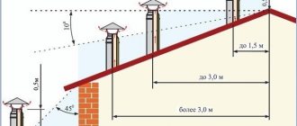
For overhead installation
CALCULATION OF HEAT LOSSES
NON-INSULATED PIPELINES
FOR OVERGROUND LAYING
METHODOLOGICAL INSTRUCTIONS
Content
| Introduction 1. Theoretical basis for calculating heat losses by uninsulated pipelines during overhead installation 2. Features of calculating heat losses through long sections of uninsulated heat pipelines 3. Practical methodology for calculating heat losses 4. An example of calculating heat losses of a pipeline Appendix A. Thermophysical characteristics of dry air |
Introduction
This document examines the features of calculating heat losses by non-insulated pipelines of heating networks during overhead installation and proposes a practical method for performing the calculation.
Calculation of heat losses by insulated pipelines must be carried out in accordance with the methods set out in the current regulatory documents /1, 2/. Characteristic of this situation is that the heat flow is mainly determined by the thermal resistance of the thermal insulation. In this case, the heat transfer coefficient on the outer surface of the covering layer has little effect on the amount of heat loss and therefore can be taken based on average values.
The operation of a heating network pipeline without thermal insulation is an atypical situation, since, according to standards, all heating pipelines must have thermal insulation in order to avoid significant heat losses. That is why no regulatory documents provide methods for calculating the heat loss of pipelines for this case.
However, during the operation of heating networks, situations can and do arise when certain sections of pipelines lack thermal insulation. To ensure the possibility of calculating heat losses through such pipelines, this methodology has been developed. It is based on the most general theoretical dependencies on the heat transfer of a pipeline under conditions of forced convection, which are given in educational and reference literature.
In accordance with the customer's requirement, all formulas and calculated values are given not in the international system of units, but in relation to the measurement of heat loss in kcal/hour.
Theoretical basis for calculating heat losses
Uninsulated pipelines
for overhead installation
The heating network pipeline is a horizontally located heated pipe, blown by the wind or located in calm air. Therefore, the heat transfer of such a pipeline can be determined by known dependencies using the heat transfer coefficient through the pipe wall:
Q = Fп ( Tп – Tв) / К, (1.1)
K = 1 / (1/αп + δм/λм + 1/αw), (1.2)
| Where | Q αп Fп Tп Tв К αп δм λм αw Tп | — — — — — — — — — — — | heat transfer of the pipeline, kcal/hour; heat transfer coefficient on the outer surface of the pipeline, kcal/(hour m2 °C); area of the outer surface of the pipeline, m2; temperature of the outer surface of the pipeline, °C; outside air temperature, °C. heat transfer coefficient through the wall of the pipeline in question, kcal/(hour m2 °C); heat transfer coefficient on the outer surface of the pipeline, kcal/(hour m2 °C); thickness of the metal pipe wall, m; thermal conductivity of the pipe wall material, kcal/(h m °C); heat transfer coefficient on the inner surface of the pipeline, kcal/(hour m2 °C); temperature of the outer surface of the pipeline, °C; |
The average temperatures for the period under consideration should be taken as the calculated temperatures. In this case, the surface temperature of the pipeline can be taken equal to the temperature of the water in the pipeline, since the thermal resistance of the pipe wall δm/λm and the heat transfer resistance on the inner surface 1/αw for a clean pipe are many times less than the heat transfer resistance on the outer surface 1/αп . This assumption makes it possible to significantly simplify the calculation and reduce the number of necessary initial data, since then it is not necessary to know the speed of water in the pipe, the thickness of the pipe wall, or the degree of contamination of the wall on the inner surface. The calculation error associated with this simplification is small and significantly less than the errors associated with the uncertainty of other calculated quantities.
The outer surface area of the pipeline is determined by its length and diameter:
Fп = π Dп L, (1.3)
| Where | Q π Dп L | — — — — | heat transfer of the pipeline, kcal/hour; constant equal to 3.141; outer diameter of the pipeline, m; pipeline length, m. |
Taking into account the above, expression (1) can be transformed to the form:
Q = αп π Dп L ( Tп – Tв ), (1.4)
The most important thing when calculating heat losses is the correct determination of heat transfer coefficients on the outer surface of the pipeline. The issue of heat transfer from a single pipe has been well studied, and calculated dependencies are given in textbooks and reference books on heat transfer. According to the theory, the overall heat transfer coefficient is defined as the sum of the convective and radiant heat transfer coefficients:
αп = αк + αл(1.5)
The convective heat transfer coefficient depends on the air speed and direction of flow relative to the axis of the pipeline, the diameter of the pipeline, and the thermophysical characteristics of the air. In the general case, the expression for determining the heat transfer coefficient on the outer surface of the pipeline with transverse air flow will be:
with laminar air movement (Reynolds criterion Re less than 1000)
αк = 0.43 βφ Re0.5 λв / Dn (1.6)
During transitional and turbulent air movement (Reynold's criterion Re is equal to or greater than 1000)
αк = 0.216 βφ Re0.6 λв / Dn, (1.7)
| Where | Re λв βφ | — — — | Reynolds criterion, calculated from the outer diameter of the pipeline and air speed, determined taking into account the height of the pipeline above the ground and the nature of the terrain. thermal conductivity coefficient of air, kcal/(h m °C); a correction factor that takes into account the direction of the air flow relative to the axis of the pipeline. |
Re = U βuDn / vв , (1.8)
| Where | U βu vв | — — — | design air speed; a correction factor that takes into account the height of the pipeline above the ground and the nature of the terrain. coefficient of kinematic viscosity of air, determined at outside air temperature, m2/s. |
The choice of the design wind speed U is a responsible task, since this parameter significantly affects the value of the convective heat transfer coefficient. The difficulty of choosing lies in the fact that wind speed is highly variable and difficult to predict, so in the calculation it is inevitably necessary to focus on some average speed values. The average value of the estimated wind speed U can be determined from actual wind speed data for the period under consideration based on meteorological observations or from monthly average values according to data /6, 7/. In this case, the first option is clearly preferable, since the data from SNiP and climatological reference books are the result of averaging over a very long period of long-term observations and cannot take into account the climate characteristics in a specific calculation year.
The value of the correction factor βu can be determined based on the wind pressure correction data given in /4/.
The relationship between the air speed correction factor and the wind pressure correction factor is quite simple:
βu = βp, (1.9)
The height of the pipeline above the ground usually does not exceed 5 m, therefore the values of the correction factor for wind speed are determined only for this situation and are given in Table 1.
Table 1— Correction factors for wind pressure and air speed
| Terrain type | Wind pressure correction βp | Correction for air speed βu |
| Open - coasts of seas and lakes, deserts, steppes, forest-steppes, tundra | 0,75 | 0,866 |
| Rough - urban areas, forested areas, etc., with obstacles up to 10 m high | 0,5 | 0,707 |
| Urban - urban areas with buildings over 20 m high | 0,4 | 0,632 |
Data on the dependence of the coefficient of kinematic viscosity vв and the thermal conductivity coefficient λв on temperature for air with an interval of 10 degrees are given in /1, 2, 3/. Appendix 1 provides the results of interpolation of these data in steps of 1 degree for direct use in calculations.
In /1/ the dependence of the correction factor βφ on the pipeline blowing angle is given. These data are presented in Table 2.
Table 2 — Correction factors for the blowing angle
| φ, deg. | |||||||
| βφ | 0,98 | 0,95 | 0,87 | 0,77 | 0,67 | 0,60 | 0,55 |
Considering that the direction of air movement in relation to the orientation of the pipeline is usually unknown, the correction factor for the blow angle βφ should be taken as the average value in the range of changes in the flow direction angle from 90 degrees (perpendicular to the pipeline axis) to 0 (parallel to the pipeline axis). According to Table 2, the average value is 0.821 .
The radiant heat transfer coefficient depends on the air temperature and the surface temperature of the pipeline, as well as on the degree of emissivity of the pipeline surface εп .
αл = εп С0 ((( Tп + 273)/100)4 – (( Тв + 273)/100) 4 ) / ( Тп – Тв ) (1.10)
| Where | C0 | — | black body emissivity. C0 =4.97 kcal/(hour m2 (°K)4) |
A bare steel heat pipe exposed to atmospheric conditions has an oxidized or highly oxidized surface, for which the degree of emissivity εp , according to data /1/, lies in the range from 0.8 to 0.98. Therefore, it is recommended to take the average value εп
= 0,9
.
Calculation of pipeline heat losses
For efficient heating of residential and commercial buildings, as well as premises for other purposes, it is necessary to provide a sufficient amount of thermal energy, and for this it is necessary to take into account heat losses in the pipeline
. To implement this task, specialists regularly carry out calculations of thermal energy losses. Various formulas are taken as the basis for calculations, but the most often taken into account is the methodology given in SNiP 2.04.14 (concerns the thermal insulation of pipelines). The formula described in the specified regulatory document can be used for any type of pipelines (with the exception of networks for transporting liquids and gases with temperatures below 0 ° C).
How to calculate heat losses
Calculations of thermal energy losses are carried out taking into account the density of the outgoing heat flow through the insulated surfaces of pipelines.
To determine the required parameter, we will use tabular data from the SNiP manual, calculated per meter of pipe.
Calculation of heat losses for pipes of a different diameter and coolants with a different temperature, which are not listed in the table, is carried out using inter- and extrapolation methods.
The estimated losses of thermal energy by the pipeline are determined by the formula:
Q = q L K B,
- where q is the value of the specific standard heat loss of a pipe 1 meter long, W/m (the average temperature of the coolant and the specified amount of annual operation of the pipeline are taken into account - the parameter is determined for each diameter based on the tabular data of SNiP 2.04.14);
- K – coefficient indicating the degree of additional heat loss from the supporting parts of pipelines and shut-off valves (tabular data is taken);
- B – coefficient indicating changes in the density of heat flows through polyurethane foam thermal insulation (for determination, the tabular values of SNiP 2.04.14 are used);
- L – total length of the pipeline network, m.
To perform calculations, it is necessary to determine the temperature of the coolants:
- the average temperature of the transported liquid or gas for a calendar year (for a continuously operating heating network);
- the average value for the period when the average daily ambient temperature drops below +8 °C (for a heating network operating during the heating season).
In the case of a two-pipe water heating network, the following calculated temperature values are taken:
- with a temperature chart of 180-70 according to DBN V.2.5-39 (pipes) / SNiP 2.04.14 ( pipeline insulation
): +100 degrees for supply, +50 for return; - 150-70: +90, +50;
- 130-70: +65, +50;
- 95-70: +55/+65, +50;
- 80-50: +45 feed, +50 return.
Such calculations do not reflect the actual losses of thermal energy, but are only intended to determine the standard value that cannot be exceeded according to SNiP.
Ways to reduce heat loss
In addition to calculations, it is also important to plan and take measures to reduce heat loss in pipelines
. For these purposes, you can perform the following tasks:
- periodically check the condition of pipelines;
- periodically drain the channels;
- replace dilapidated and frequently damaged sections of pipes;
- clean drains;
- apply/restore anti-corrosion, heat and waterproofing coatings;
- increase the pH of the transported water;
- ensure high-quality water treatment of the makeup fluid;
- organize electrochemical protection of the pipeline;
- restore waterproofing at the joints between floor slabs;
- provide ventilation of the ducts;
- install bellows expansion joints;
- use improved pipe steel and non-metallic pipelines;
- determine actual heat losses in real time using thermal energy metering devices;
- strengthen supervision during emergency restoration work;
- use not central, but individual heat points for heat supply to consumers.
Information on the purpose of the calculator
The heat loss calculator is designed to calculate the approximate amount of heat lost by a room through the building envelope per unit of time during the coldest five-day period of the selected locality (according to the updated version of SP 131.13330.2012).
Information is current as of 2022.
These calculations are quite approximate, since it is impossible to take into account absolutely all factors influencing heat losses, and the results obtained must be verified experimentally to confirm the calculations. Errors in wall design can also significantly affect actual heat loss. For example, the formation of condensation inside a wall structure can significantly increase the thermal conductivity of the insulating material during the winter.
Also, the overall heat loss is affected by the difference between external and internal temperatures, solar radiation, precipitation, wind and other factors. Modeling the heat loss processes of an entire building is an urgent problem. Knowing the heat loss of the building, you can proceed to choosing the power and options for the heating system.
To reduce the heat loss of a building, it is necessary to use the most effective thermal insulation materials. It is especially worth paying attention to the roof, since it is through it that the greatest amount of heat from the room escapes outside. To maintain a comfortable internal microclimate, as well as reduce financial costs for heating, it is necessary to maintain the correct balance of insulation of all building envelopes.
Approximate minimum quality of insulation of external walls
- Good:
- Average:
- The bad:
~ 300 mm Wood + 100 mm Polystyrene/Rock Wool
~ 500 mm Gas and foam concrete
~ 300 mm Gas and foam concrete + 100 mm Polystyrene/Rock Wool
~ 400 mm Expanded clay concrete + 100 mm Polystyrene/Rock Wool
~ 250 mm Brick + 200 mm Polystyrene/Rock Wool
~ 300 mm Wood + 50 mm Polystyrene/Rock Wool
~ 400 mm Gas and foam concrete
~ 300 mm Gas and foam concrete + 50 mm Polystyrene/Rock Wool
~ 200 mm Expanded clay concrete + 100 mm Polystyrene/Rock Wool
~ 250 mm Brick + 100 mm Polystyrene/Rock Wool
~ 200 mm Wood
~ 200 mm Gas and foam concrete
~ 100 mm Gas and foam concrete + 120 mm Brick
~ 300 mm Expanded clay concrete
~ 250 mm Brick
How to calculate heat losses of pipelines
Determining heat losses during coolant transportation is a task, the results of which influence the correct choice of heat source. Determining the actual losses of thermal energy by pipelines and comparing them with standard values allows for timely repair of the heating main with replacement of pipes or their thermal insulation.
Factors influencing heat loss from a pipeline
According to existing methods, calculations of standard heat losses take into account the length and diameter of the pipeline, the temperature of the medium, and the ambient temperature.
The values of relative heat losses are reduced to values that are multiples of five.
This technique does not correspond much to reality, since it does not take into account the actual state of pipeline insulation and leakage of the coolant itself. (See also: Do-it-yourself installation of solid fuel boilers)
However, even having received data refined by taking into account all quantities along the entire length of a significant route, it is impossible to talk about the reliability of these data for a specific section of the pipeline.
In addition to the main parameters: the length and diameter of the pipeline, the temperature of the carrier, air and soil, the condition of the insulating coating, the amount of heat loss is significantly influenced by the speed of movement of the coolant through the pipe and the number and power of consumers that are connected to the route. If there are small consumers located at considerable distances in the system, heat losses increase significantly. A compact system with several large consumers has virtually no heat loss.
Therefore, if the calculation of heat losses of pipelines shows significant heat losses for remote small consumers, then the task of transferring such structures to individual heating becomes advisable. This technique also makes it possible to identify areas of greatest losses and show the economic effect of replacing a given section of pipe. (See also: Total heat loss for heating)
Installation of heat meters - ensuring accuracy of calculations
Such an examination of heat loss is most accurate and convenient to carry out if consumers, at least most of them, have heat meters. The most acceptable option is a heat meter with hourly data storage in the archive.
The information obtained thanks to the meters allows you to easily determine the temperature of the coolant at various points in the network and its flow.
The surveys carried out and comparison of the data obtained show that pipelines laid in non-passable channels and in operation for more than 15 years have heat losses that are 1.5 - 2 times higher than the standard values.
These results are valid for pipes that have no visible damage. And pipelines with visible damage have heat losses that are 4 to 6 times greater than the values set by the standards.
Formula for calculating the amount of heat loss
As a calculation formula, we can propose a formula that takes into account the presence of thermal insulation, its thickness and physical properties. (See also: Choosing a heated floor)
- Q = 2π*Ktp*L*(Tr – Tu)/Ln* (D/d)
- In this formula, Q is the amount of heat loss, W; Ktp – thermal conductivity coefficient of the insulating material, W/m*s; L – pipeline length, m; Tr – coolant temperature; Tu – ambient temperature; π – number “pi”; D – outer diameter of the pipeline with insulation; d – outer diameter of the pipe without insulating coating.
- This formula allows you to calculate the amount of heat loss by the pipeline with a fairly high degree of reliability.
Calculation of pipe heat transfer in Excel.
To perform calculations, you must enter the source data into the MS Excel table. There are 13 of them. These are the physical parameters of the coolant (water), the ambient temperature, the geometric dimensions of the pipe and the thermal insulation layer, the thermal conductivity of the materials and the degree of blackness of the outer surfaces of the pipe and insulation.
The results cells automatically display the value of the heat output power of the pipe in Watts for four options, and the cooling temperature of the water in degrees Celsius during movement along a given section of the pipeline.
All 22 user functions involved in this Excel calculation program are each recorded in their own Module in the Modules folder. Access to the folder is in the Visual Basic Editor.