Set of socks, Omsa socks
349 ₽ More details
Set of socks, Omsa socks
349 ₽ More details
Plaster on drywall
Maintaining temperature conditions is a very important technological condition not only in production, but also in everyday life. Having such great importance, this parameter must be regulated and controlled somehow. They produce a huge number of such devices, which have many features and parameters. But making a thermostat with your own hands is sometimes much more profitable than buying a ready-made factory analogue.
Make your own thermostat
General concept of temperature controllers
Devices that record and simultaneously regulate a given temperature value are more common in production. But they also found their place in everyday life. To maintain the necessary microclimate in the house, water thermostats are often used. They make such devices with their own hands for drying vegetables or heating an incubator. Such a system can find its place anywhere.
In this video we will find out what a temperature regulator is:
In reality, most thermostats are only part of an overall circuit, which consists of the following components:
- A temperature sensor that measures and records, as well as transmits the received information to the controller. This happens due to the conversion of thermal energy into electrical signals recognized by the device. The sensor can be a resistance thermometer or a thermocouple, which have metal in their design that reacts to changes in temperature and changes its resistance under its influence.
- The analytical unit is the regulator itself. It receives electronic signals and reacts depending on its functions, after which it transmits the signal to the actuator.
- An actuator is a kind of mechanical or electronic device that, when receiving a signal from the unit, behaves in a certain way. For example, when the set temperature is reached, the valve will shut off the coolant supply. Conversely, as soon as the readings drop below the specified values, the analytical unit will give a command to open the valve.
These are the three main parts of the system for maintaining specified temperature parameters. Although, in addition to them, other parts, such as an intermediate relay, may also participate in the circuit. But they perform only an additional function.
A little theory
Any thermostat structurally includes three main blocks:
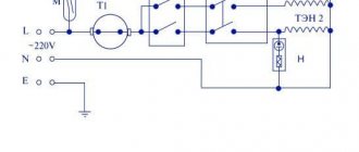
Theoretically, a temperature sensor can be represented by a set of four resistances, among which three resistors will be represented by elements with constant electrical parameters, and the fourth by variable ones. They are assembled into a measuring half-arm circuit shown in Figure 1 below:
The diagram shows the principle of connecting resistors to obtain a temperature sensor. As you can see, resistance R2 is variable and changes its physical value in accordance with changes in ambient temperature. When the same supply voltage is supplied to the thermostat, when the resistance in the arm changes, the current in the circuit will increase.
Based on the changes, temperature fluctuations are analyzed, as a result of which the working element causes the thermostat to operate and subsequently turn off or turn on the equipment.
To measure the resistance of resistors, a microcircuit operating in comparator mode is installed as a logical element. Its task is to compare the electrical signals in the two arms. An example of a temperature controller circuit is shown in the figure:
Here, the U1A microcircuit block receives signals from the temperature meter at inputs 2 and 3. When the response temperature is reached, different currents will begin to flow in the arms, and the comparator will send a signal to turn on to the control element of the electronic thermostat.
When the thermometer sensor cools down, the current in the arms of the thermostat will equalize, and the electronic unit will issue a control signal to turn off. The above electronic circuit operates in two stable states - off and on, alternating operating modes occurs in accordance with a given logic.
This thermostat circuit is used in the operation of a personal computer cooler; receiving power from the power supply, the current in the arms is compared. When the power supply overheats, the thermostat will switch the transistor to the opposite state and the fan will start.
This principle can be used not only in fans, but also in a number of other devices:
- to control the operation of electric heating based on temperature readings in the room;
- to set the temperature level in a homemade incubator;
- when connecting a heated floor to control its operation;
- to set the temperature range of engine operation, with forced cooling or shutting down the system when the temperature limit is reached;
- for soldering stations or hand soldering irons;
- in cooling systems and refrigeration equipment with the logic of reducing temperature within certain limits;
- in ovens and stoves for both household and industrial purposes.
The scope of application of the thermostat is not limited in any way; wherever you want to control the temperature level in automatic mode with power management, such a device will be an excellent assistant.
Principle of operation
The principle on which all regulators work is the removal of a physical quantity (temperature), transmission of data to the control unit circuit, which decides what needs to be done in a particular case.
If you are making a thermal relay, the simplest option will be to have a mechanical control circuit. Here, using a resistor, a certain threshold is set, upon reaching which a signal will be given to the actuator.
To get additional functionality and the ability to work with a wider temperature range, you will have to integrate a controller. This will also help increase the service life of the device.
In this video you can see how to make your own thermostat for electric heating:
How to install correctly
To extend the life of the thermostat, use the following recommendations:
- do not install electronics without additional protection outdoors or in rooms with high humidity levels;
- if necessary, remove the control sensor into an unfavorable environment;
- exclude the placement of the regulator opposite heat guns or other “generators” of cold or heat;
- To increase accuracy, choose a location without active convection currents.
Homemade temperature controller
There are actually a lot of schemes for making a thermostat yourself. It all depends on the area in which such a product will be used. Of course, it is extremely difficult to create something too complex and multifunctional. But a thermostat that can be used to heat an aquarium or dry vegetables for the winter can be created with a minimum of knowledge.
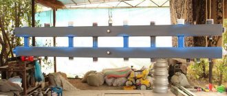
This is useful: distribution manifold in a heating system.
The simplest scheme
The simplest do-it-yourself thermal relay circuit has a transformerless power supply, which consists of a diode bridge with a parallel-connected zener diode that stabilizes the voltage within 14 volts, and a quenching capacitor. If desired, you can also add a 12-volt stabilizer here.
Creating a thermostat does not require much effort or financial investment.
The entire circuit will be based on a zener diode TL431, which is controlled by a divider consisting of a 47 kOhm resistor, a 10 kOhm resistance and a 10 kOhm thermistor that acts as a temperature sensor. Its resistance decreases with increasing temperature. It is better to select the resistor and resistance to achieve the best operating accuracy.
The process itself is as follows: when a voltage of more than 2.5 volts is generated at the control contact of the microcircuit, it will make an opening, which will turn on the relay, applying a load to the actuator.
You can see how to make a thermostat for an incubator with your own hands in the video presented:
Conversely, when the voltage drops lower, the microcircuit will close and the relay will turn off.
To avoid rattling of the relay contacts, it is necessary to select it with a minimum holding current. And parallel to the inputs you need to solder a 470×25 V capacitor.
When using an NTC thermistor and a microcircuit that have already been used, you should first check their performance and accuracy.
Thus, we get the simplest device that regulates the temperature. But with the right ingredients, it works excellently in a wide range of applications.
Indoor device
Such do-it-yourself thermostats with an air temperature sensor are optimally suited for maintaining the specified microclimate parameters in rooms and containers. It is fully capable of automating the process and controlling any heat emitter, from hot water to heating elements. At the same time, the thermal switch has excellent performance data. And the sensor can be either built-in or remote.
Here the thermistor, designated R1 in the diagram, acts as a temperature sensor. The voltage divider includes R1, R2, R3 and R6, the signal from which is sent to the fourth pin of the operational amplifier chip. The fifth pin of DA1 receives a signal from the divider R3, R4, R7 and R8.
The resistance of the resistors must be selected in such a way that at the minimum low temperature of the measured medium, when the resistance of the thermistor is maximum, the comparator is positively saturated.
The voltage at the output of the comparator is 11.5 volts. At this time, transistor VT1 is in the open position, and relay K1 turns on the actuator or intermediate mechanism, as a result of which heating begins. As a result, the ambient temperature rises, which reduces the resistance of the sensor. At input 4 of the microcircuit, the voltage begins to increase and, as a result, exceeds the voltage at pin 5. As a result, the comparator enters the negative saturation phase. At the tenth output of the microcircuit, the voltage becomes approximately 0.7 Volts, which is a logical zero. As a result, transistor VT1 closes, and the relay turns off and turns off the actuator.
On the LM 311 chip
This do-it-yourself temperature controller is designed to work with heating elements and is capable of maintaining the specified temperature parameters within the range of 20-100 degrees. This is the safest and most reliable option, since its operation uses galvanic isolation of the temperature sensor and control circuits, and this completely eliminates the possibility of electric shock.
Like most similar circuits, it is based on a direct current bridge, in one arm of which a comparator is connected, and in the other - a temperature sensor. The comparator monitors the mismatch of the circuit and reacts to the state of the bridge when it passes the balance point. At the same time, he tries to balance the bridge using a thermistor, changing its temperature. And thermal stabilization can occur only at a certain value.
Resistor R6 sets the point at which balance should be formed. And depending on the temperature of the environment, the thermistor R8 can be included in this balance, which allows you to regulate the temperature.
In the video you can see an analysis of a simple thermostat circuit:
If the temperature set by R6 is lower than required, then the resistance on R8 is too high, which reduces the current on the comparator. This will cause current to flow and open the semistor VS1 , which will turn on the heating element. The LED will indicate this.
As the temperature rises, the resistance of R8 will begin to decrease. The bridge will tend to a balance point. On the comparator, the potential of the inverse input gradually decreases, and on the direct input it increases. At some point the situation changes, and the process occurs in the opposite direction. Thus, the temperature controller will turn the actuator on or off depending on the resistance R8.
If LM311 is not available, then it can be replaced with the domestic KR554CA301 microcircuit. It turns out to be a simple do-it-yourself thermostat with minimal costs, high accuracy and reliable operation.
Creating a simple thermostat
When repairing household electrical appliances, you may have encountered a situation where the thermostat failed. Although this is a small microcircuit installed to control the amount of heating or cooling of something.
Alas, the cost of such a factory-made element is quite high, so it is much more profitable to assemble the thermostat yourself. A diagram of a fairly simple homemade thermostat is shown in the figure below.
Rice. 5. Diagram of a simple thermostat
To make it you will need:
- step-down transformer from 220 to 12 V;
- six diodes (in this example, IN4007 are used);
- capacitors 47 µF, 1 mF and 2 mF;
- microcircuit for a 5V stabilizer;
- transistor (in the example under consideration it is KT814A);
- Variable zener diode (TL431);
- resistive elements at 4.7; 160, 150 and 910 kOhm;
- resistor with variable resistance 150 kOhm;
- temperature dependent resistor 50 kOhm;
- Light-emitting diode;
- electromagnetic relay 100 mA with a supply voltage of 12V (in the example under consideration, an automobile version is used);
- button and body.
The manufacturing process consists of the following stages:
- Using a soldering iron, assemble the above parts onto a printed circuit board as shown in the diagram above.
- After this, take the measuring element for the thermostat out into the open space to install it in the desired location.
Rice. 6. Output the measuring element
- Install a variable resistor on a rigid frame and apply a temperature scale to set up the device.
Rice. 7. Install the regulator on the frame and apply the graduation
- Connect the power cord to the terminal block.
Connect the power cord to the terminal block.
In this case, the terminal block was taken from an old device located in the housing.
- Connect all separately placed elements to the board and cover with the housing.
After assembling the thermostat, it can be installed in any place, for example, for heating and connected to the power circuit of an electric boiler. If the heating radiators heat the room to the set temperature, the relay contacts will break the circuit and stop the power supply. When the digital thermometer cools down, the heating will turn on again and heat up again. If you are not satisfied with the temperature regime, you can change it by setting the sensor.
Advantages and disadvantages
Even a simple do-it-yourself thermostat has a lot of advantages and positive aspects. There is no need to talk about factory multifunctional devices at all.
Temperature regulators allow:
- Maintain a comfortable temperature.
- Save energy resources.
- Do not involve a person in the process.
- Follow the technological process, increasing quality.
The disadvantages include the high cost of factory models. Of course, this does not apply to homemade devices. But the production ones, which are required when working with liquid, gaseous, alkaline and other similar media, have a high cost. Especially if the device must have many functions and capabilities.
Switching on the load
An automotive relay can be used as an actuator that supplies power to the heater. It is designed for a voltage of 12 V, while a current of 100 mA must flow through the coil.
Let us remember that the current in the temperature sensor circuit does not exceed 5 mA, so to connect the relay you need to use a transistor with higher power, for example, KT814.
You can use a relay with a lower turn-on current, such as SRA-12VDC-L or SRD-12VDC-SL-C - then a transistor will not be needed.
Assembly
Having prepared the above materials and tools, we proceed to soldering a simple circuit.
- The positive terminal of the power supply is connected by a wire to the input contact (+) of the cooler;
- The three terminals of the field-effect transistor are soldered with wires like this: “source” with a cooler, “gate” with a thermistor, “drain” with a variable resistor.
- Wires connect the free contacts of the thermistor to the “+” of the power supply, and the variable resistor to the “−” of the same block.