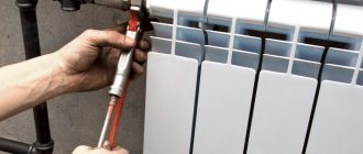
In heating systems of multi-storey buildings, you can often see a jumper in front of the heating radiator that connects the coolant supply and outlet pipes. It would seem, why complicate the design and additionally install a jumper connecting the pipes? This does not provide any savings or reduce the cost of the project. But in practice, the bypass to the heating radiator is installed in strict accordance with the design of the heating system and, at the same time, in compliance with the technical conditions for such jumpers. So it’s worth understanding this issue thoroughly.
What is a battery jumper and what is it for?
First of all, in order to determine why a bypass is needed on a heating radiator, it is worth saying that it is not installed on all heating systems. The fact is that such devices are not installed in an apartment building equipped with a two-pipe heating system. The coolant in a two-pipe system enters the battery from the hot water supply pipe, and is discharged directly into the return pipe, so if it is necessary to turn off the battery on one of the floors, nothing bad will happen to the system, the taps will simply be turned off at one point, and the coolant will continue to circulate in system.
It's another matter when the building is equipped with a single-pipe heating system. Here the issue is more difficult to solve - the coolant flows through the pipes to the highest point, where the distribution is made through the risers. The riser pipe is connected to the battery, the coolant, passing through the radiator registers at the outlet, enters another section of the pipe, which descends to the floor below. Then the scheme is repeated, and so on until the basement. Everything would seem simple - fewer pipes, easier for the coolant to move through the system. But, as we know, there are no perfect systems; this, at first glance, simple scheme also has flaws. First of all, this is the cooling rate of the coolant - it turns out with each battery, it becomes colder and colder. The second point is that if one battery breaks down, you will have to shut off the entire riser, because by turning off the valve for supplying and draining water from the radiator, the entire chain is interrupted and the riser stops working. A way out of this situation was found - a jumper on the heating battery. Simple and rational.
Alternative ways to raise your temperature
The surest solution is to increase the number of radiator sections. The longer the heating device, the more heat it can release into the room. Second method: replace the fans installed at the inlet of the heat flow battery with standard ball valves. Ball valves allow water to pass through the entire ceiling without restriction. Unfortunately, using such a faucet you cannot adjust the coolant flow. A plus is good water circulation in all directions. Another disadvantage of ball valves is the effect of sticking of internal parts. After a long period of inactivity, the faucet stops turning off the flow of water. Ball valves require periodic maintenance. They must be opened and closed periodically.
What are the requirements for the jumper?
The side jumper to the heating radiator, as already mentioned, is installed in single-pipe heating systems. According to the requirements for the installation of heating systems, such devices should be installed closer to the battery. The second requirement is that the bypass be made of the same material as the main main pipe. If steel pipes are used in the building, then the lintel is also made of steel pipe. If metal-plastic pipes or polypropylene are connected from the main pipe to the battery, then the jumper is made of this material.
The third requirement for installing jumpers in front of the battery is that such a device is installed taking into account the dimensions of the pipes of the main pipeline. The jumper is always installed with a smaller diameter than the inlet and outlet pipes. Most often the difference is taken to be 1 size. For example, if the main pipe is ¾" in diameter, then the bypass should be ½" in diameter.
How does the bypass work under normal conditions?
So, if we discard the subtleties of calculations and formulas, we can imagine the operation of this unit of the heating system as follows. From the top floor, coolant is supplied through the supply pipe to the bypass installation point. As we know from physics courses, both electric current and liquid always move in the direction of least resistance. If water gets from a 3/4-inch diameter pipe into the section leading to the battery, it will be easier for water to penetrate into the larger diameter pipe. Therefore, only a small part of the coolant enters the bypass with a diameter of ½ inch, the rest of the pressure moves into the battery through a pipe with a diameter of ¾ inch, then it passes through the taps and thermostat and goes into the battery registers. After passing through and partially cooling, the water again exits through the ¾-inch pipe into the main line, and passing through the shut-off valve, it connects with the flow from the bypass and moves further in the general flow.
At normal pressure and high temperature, the temperature loss in this area will be insignificant, unless the apartment owner has installed an additional three-meter air-flow battery.
In the event of an emergency situation, for example, depressurization of the radiator for repair work, an emergency shutdown of the branch to the battery is performed - the taps on the supply and outlet pipes are closed. This is where the bypass comes into play. The coolant, coming from the upper floor, moves along the only possible route - through the jumper and further along the pipe to the lower floor. Thus, the jumper allows you not to disconnect the entire riser from the coolant supply, which allows you to correct the situation with the least losses and in the shortest possible time.
OR-13.02-45.21.30-KTN-002-1-03
- a group (groups) of tanks intended for storing oil and petroleum products and located in an area limited along the perimeter by an embankment or enclosing wall for above-ground tanks and roads or fire-fighting passages for underground tanks and tanks installed in pits or excavations.
- an electrical connection that ensures the equalization of electrical potentials between objects and the ground.
- a room or a limited space in a room or outdoor installation in which explosive mixtures are present or may form. The classification of hazardous areas is determined according to clause 7.3 [11].
- a liquid whose specific volumetric electrical resistance exceeds 108 Ohm m-1.
- a conductor (electrode) or a set of interconnected metal conductors (electrodes) in contact with the ground.
- a grounding conductor designed to drain lightning currents into the ground or limit overvoltages that occur on metal enclosures of equipment during close lightning strikes. Grounding electrodes are used natural and artificial.
- specially laid contours in the ground made of strip or round steel, consisting of vertical and horizontal conductors.
- a grounding conductor, which is used as electrically conductive parts of construction and industrial buildings and structures buried in the ground.
- a conductor connecting the grounded parts to the ground electrode.
— a set of structurally combined grounding conductors and a grounding conductor.
- a grounding conductor with two or more branches.
the ratio of the voltage on the grounding device to the current flowing from the ground electrode into the ground.
a set of protective devices and structures (lightning rods, down conductors, grounding devices, etc.) designed to ensure the safety of people, protect tank farms of oil pumping stations and oil depots from the dangerous effects of lightning, its secondary manifestations (high potential drift, electromagnetic induction), electrostatic induction and static electricity.
— a set of protective devices designed to ensure the safety of people, the safety of buildings and structures, equipment and material assets from possible explosions, fires and destruction resulting from lightning.
- a device that receives a lightning strike and discharges its current into the ground, consisting of an lightning rod, a down conductor and a grounding device, which allows protecting tanks and other objects of oil pumping stations and oil depots from direct lightning strikes.
— a single design of a rod or cable lightning rod.
— two (or more) rod or cable lightning rods forming a common protection zone.
- a device that directly perceives a lightning strike.
conductor connecting the lightning rod to the grounding device.
- a spark discharge that occurs under the influence of a field of static electricity charges, as a result of the introduction of high potential and secondary manifestations of lightning.
- a space within which a building or structure is protected from direct lightning strikes with a reliability not lower than a certain value.
— lightning rods, the supports of which are installed on the ground at some distance from the protected object.
- direct contact of the lightning channel with a building or structure, accompanied by the flow of lightning current through it.
induction of potentials on metal structural elements, equipment, in open metal circuits, caused by nearby lightning discharges and creating the danger of sparking inside the protected object.
- induction of potentials in open metal circuits as a result of rapid changes in current, creating the danger of sparking in places where these circuits come together.
- induction of potentials on ground objects as a result of changes in the electric field, creating the danger of sparking between metal elements of structures and equipment.
— transfer into the protected building or structure via long metal communications (underground and above-ground pipelines, cables, etc.) of electrical potentials that arise during direct and close lightning strikes and create the danger of sparking inside the protected object.
accumulation of electrical charges as a result of electrification of non-electrically conductive substances (materials) creating an electric field and electrical potentials that can cause sparking or harmful effects on people and animals, disrupt the operation of devices, equipment, etc.
- a liquid capable of burning independently after removal of the ignition source and having a flash point not higher than 61 C.[11]
What types of bypasses are there?
Heat engineering offers three types of jumpers installed in single-pipe heating systems. Each type is used depending on the purpose of the system and the availability of additional equipment. Thus, the following types of jumpers are distinguished:
- Simple unregulated;
- Jumpers with manual adjustment;
- Bypasses with automatic flow control.
The first type is a simple piece of pipe connected in front of the battery to the heating supply and discharge pipes. This is the simplest and at the same time reliable type of bypass.
A jumper with manual flow control is a piece of pipe with a valve-regulator installed in the middle. The installation of such a device in the heating systems of multi-storey buildings is still controversial. The fact is that the coolant flow is adjusted manually by turning the tap a certain number of divisions, until the flow is completely blocked. In normal conditions, this allows you to direct the entire flow of coolant through the battery, but in the event of an emergency, you can forget to open the tap and the riser will remain, at best, simply without heat; in the worst case, you will have to repair the entire riser and replace ruptured batteries on all floors of the building.
An automatic bypass is an injection or valve type device installed in autonomous heating systems. The essence of this device is as follows: to increase the coolant flow rate in systems with natural coolant circulation, a pressure pump is often used. This device is usually installed on a section of heated floor. When the power is turned off, the coolant moves around the pump impeller, through the jumper, thus ensuring the operability of the system. The big disadvantage of the automatic bypass is its dependence on the quality of the coolant. The water in the system must be as clean as possible and free from lime deposits, impurities and scale. This is why additional strainers are used when installing an automatic bypass.
Purpose of bypass sections
The circulation of the coolant is maintained in the bypass pipelines in cases of failure of the pumping unit, or during a lack of power supply. Any heating element controlled by bypass can be turned off or completely disconnected from the common main by directing the flow through a bypass pipe by closing the valves on the inlet and outlet pipes. Thus, during scheduled maintenance of the heating system, there is no need to turn it off and completely drain the liquid.
In individual heating systems of private houses, contours are used for:
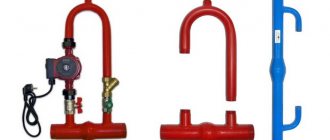
When piping the circulation pump, the bypass acts as the main pipeline. Therefore, it is into the bypass pipe that the shut-off valves are installed, and not at the inlet or outlet pipes. Only this installation method can eliminate media recirculation.
Diagram for installing a jumper in the system
The correct option for installing a jumper in the system is to install a bypass in mandatory connection with shut-off valves at the inlet and outlet of the coolant from the battery. Practice shows that it is quite reasonable to install a temperature regulator in addition to the taps after the bypass. But here it is necessary to emphasize that it is reasonable to install such a regulator in new systems, in which there is no need to call specialists to clean the batteries, and the heating season itself passes without complications and accidents.
Another thing is when the radiators heat poorly, the boiler room cannot cope with the supply of coolant. In such cases, there is a temptation to install the tap on the bypass, making it adjustable, and simply closing the jumper, directing the entire flow to the battery, making it 2-3 degrees hotter. For an experienced heating engineer, this is usually not difficult to do - in the summer, the riser is usually turned off, the water is drained and the tap is turned on. But from this moment on, it is necessary to remember that already when the heat supply is turned on in apartments on the lower floors, the difference in temperature will be felt much more acutely. In this case, you need to be prepared for the fact that during the first round, utility workers will find the tap installed and demand that it be removed. The official reason for such a requirement will be a violation of the thermal balance of the building, even if before this the boiler room worked poorly and the radiators were slightly warm. But the law will be on the side of the utility companies, so such an improvement will not only have to be dismantled, but also, most likely, they will have to pay for the restoration of the building system.
As you can see, the correct installation of a bypass in the system of an apartment building is a very troublesome task. Of course, if you have experience working with gas welding equipment and knowledge of the location of heating shut-off valves throughout the house, then shutting off the riser and installing the battery may be a common task, but even in this case, it is recommended to contact the professionals responsible for the heating system of the house.
Additional circulation pumps
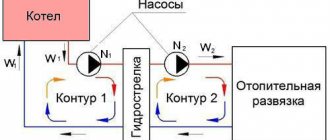
The circulation pump (hereinafter referred to as CN), as a rule, is installed on the coolant return pipe (return). The classic place for inserting a bypass with an installed pump is in close proximity to a gas, electric, diesel, solid fuel boiler, but this cannot be the rule. For example, for a two-story house, the power of an integrated or near-boiler central heating system may not be enough, and then it is installed on the second floor to ensure proper water rise. In addition, the central pump can be embedded in a remote wing of the building to ensure uniform circulation of fluid throughout the pipeline.
1 – the heating circuit serves as a bypass; 2 - the bypass pipe serves as a bypass Source cementequipment.org
As mentioned above, either the main or bypass branch of the circuit can be used as a bypass (see photo above). Most often, the section under the central passage and the main passage have different diameters, but this is not necessary. Taking into account the forced suction of liquid, the diameter on the bypass with a pump is usually smaller, for example, bypass Ø 32 mm, and on the central pump - 25 mm. But here it should be noted that not only calculations, but also many years of experience of plumbers indicate that the diameter of the pipes at this unit should be different.
Note! The material in the assembly may vary. For example, in a house where a steel heating circuit has been installed for a long time, the need arose to install a central heating system. In this case, the bypass for the circulation pump can be made not only from steel, but also from PPR (polypropylene) PN20 or PN25. You just need to choose the right Dy (inner diameter), although in small systems it is permissible (and more convenient) to focus on Dn (outer diameter).
Assembly and installation
Having purchased a bypass for the central heating unit, you will have to assemble it yourself Source scparts.co.uk
If you are interested in an automatic bypass, then this is from the realm of fantasy: a hollow profile or bypass cannot be automated, since it is just a piece of metal (steel, copper, brass) or polypropylene . If we talk about installing a central pump, then this unit can be purchased in a store and it is pre-provided with pipes for mounting the pump. If you have a metal heating circuit, then this is very convenient, but when the piping is made of PPR, then this unit will have to be welded yourself, however, it is not so difficult.
Before assembly, you will have to decide how you will pack the docking units: with fum tape or cable ties. Old plumbers from the times of the USSR always advocate the second option, but many years of practice suggest that both materials are perfect for this purpose, and fumka is much more practical in work. But, no matter what material you prefer, Unipak plumbing paste will never be superfluous - it is smeared over tape or tow to ensure a reliable connection (without leaks).
The arrow on the pump must correspond to the direction of the coolant Source homedepot.com

