Collector distribution of water supply pipes in an apartment
Collector distribution of water supply pipes in an apartment differs from the standard system by the installation of a T-shaped distributor. The wiring diagram has many advantages, one of the important ones is adjusting the pressure so that it is the same along the entire length of the pipeline, making the process of repairing outdated sections easier.
Collector device - what is it? The collector device is a plumbing part that helps mix the water of two branches; from the collector, water flows to different points in the system. From the device, the water is divided into streams that have the same pressure. Thus, the manifold is considered to be a fluid distributing mechanism.
It is installed on the central riser pipe. Collector wiring involves installing a collector. The design of the collector is simple; you can install it yourself.
Selection of distribution manifold
The main rule is that the diameter of the collector should in no case be less than the size of the supply line pipe.
The larger the diameter of the distribution “comb”, the better for uniform pressure at the points of water and/or coolant collection. Incorrect selection of the “comb” (see recommendations above), for example, for a water supply system, can cause jumps in flow rate on different devices (see Fig. 2) and cause imbalance, for example, on a mixer.
Rice. 2. The result of incorrect selection of collectors for cold and hot water supply
If control valves are not installed at the apartment inlet of hot and cold water to forcibly stabilize the pressure in the “comb”, then for apartment collectors it is especially important to adhere to the rules of the connection sequence. It is necessary to connect devices, the uneven flow of which has little effect on the performance or comfort of the water supply, as “lower” as possible downstream of the water in the “comb”
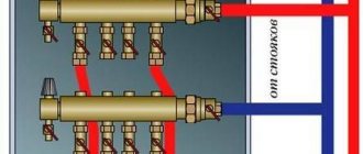
The water heater should be connected first, then the faucets, then the washing machine and dishwasher (making sure that the “no water” shut-off valve is set to a pressure lower than the drop caused by the change in water supply), and at the very end of the manifold - the cistern drain pipe ( see Fig. 3).
Rice. 3 Example of connecting an apartment cold water distribution manifold
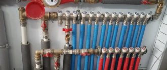
Rules for installing water supply systems
For the water supply you will also need two collectors: one for hot water, the second for cold water.
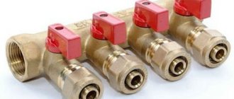
In this case, there is no need to install control valves - a shut-off valve is sufficient. Typically, taps on manifolds for cold water are equipped with blue handles, and for hot water - red.
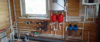
The water supply manifold should be installed in a dry place: in a closet, for example, or in a corridor.
The ideal option is installation in a cabinet (the collector is equipped with special fasteners), but if you are not going to spend money on buying it yet, you can simply place the part in some niche.
As already mentioned, the absence of connections on the pipes between the devices and the collector allows them to be laid in a hidden manner. It should be taken into account that gating of load-bearing walls is not allowed. When laying hidden, all pipes, even with cold water, must be covered with a sleeve made of foamed polyethylene. This material will provide the gap between the pipe walls and the solution necessary to compensate for free thermal expansion.
Bathroom renovations involve not only replacing plumbing fixtures, but also installing new pipes. Laying out pipes in the bathroom with your own hands - dismantling used pipes and methods for installing new equipment, read about this in the next topic.
Is it worth it to drain the floor in a shower and what are the advantages and disadvantages of a simplified drain system? Read this link.
Solar collector savings opportunity
It is possible to connect several coolant heating sources to the heating circuit. Often solid fuel boilers operate in parallel with electric ones. this allows you to maintain the operating mode of the heating system at night or in the absence of owners for several days.
But this mode cannot be called economical - electricity is one of the most expensive resources. Modern developments make it possible to use solar energy to heat the coolant by installing a solar collector.
The solar collector is an installation that can be used all year round, even in cloudy temperatures. On sunny days it is most effective and heats up to the temperature of the boiler supply circuit - up to 70-90 degrees.
Homemade solar collector
A solar collector is a fairly simple device; it is not difficult to make it yourself. In terms of efficiency, a homemade solar water heater may be inferior to industrial models, but given their price - from 10 to 150 thousand rubles, a solar collector made by yourself will very quickly pay for itself.
To make it you need:
- a coil made of a metal tube, usually copper, you can take a suitable one from an old refrigerator;
- scraps of copper pipe with a 16 mm thread on one side;
- plugs and valves;
- pipes for connection to the collector unit;
- storage tank with a volume of 50 to 80 liters;
- wooden planks for making a frame;
- sheet of expanded polystyrene 30-40 mm thick;
- glass, you can take window glass;
- thick aluminum foil.
The coil is freed from freon residues by washing it with a stream of running water. A frame with a size slightly larger than a coil is made from a wooden lath or block. Holes are drilled in the lower part of the frame to remove the coil tubes.
On the reverse side, a sheet of polystyrene foam is attached to it with glue or self-tapping screws - this will be the bottom of the collector. This material has excellent thermal insulation characteristics, which will help reduce heat loss.
The top of the solar collector is covered with glass, securing it to glazing beads or slats. Pipes are attached to the ends of the coil for connection to the heating manifold unit. This can be done using adapters or flexible liners.
The collector is placed on the southern slope of the roof. The pipes lead to a storage tank equipped with an air valve, and from there to the heating distribution manifold.
Video: how to make your own solar heater
A manifold heating system is the most efficient way to connect different heaters to one or more heating sources. With its help, you can ensure stable temperature and comfort in the house, as well as uninterrupted and coordinated operation of all elements of the system.
Rules for installing heating systems
In heating systems, two collectors are used - supply and return. If the system is supposed to be balanced manually, control valves and balancing flow meters are connected to the supply manifold pipes, and shut-off valves are installed on the return side.
Theoretically, instead of control valves, you can use cheaper shut-off valves - with its help you can also change the amount of fluid flow. But in this case, it will quickly fail, since it is not designed for this mode of operation.
Collector heating system
If there is a thermostat in the heating system, instead of manual taps, fittings with servo drives are installed on the supply manifold. In this case, the coolant flow through each radiator will be adjusted automatically.
The supply manifold should be located higher than the return manifold. The pipes themselves can be laid any way you like.
If in a traditional radiator connection scheme the supply line must be higher than the return line, then in the collector line their location does not matter at all. Therefore, pipes are most often laid inside the floor.
Advantages of the scheme
Heating systems for a country house
The advantages of this coolant supply scheme are ease of use. Operation of the system and control of heating devices are as comfortable as possible:
- The temperature of each circuit element can be controlled centrally. Being near the collector, the homeowner can limit the supply of coolant to any register or turn it off completely. It is convenient to control the temperature in each room.
- Each branch that extends from the collector feeds only one radiator. Therefore, small-diameter pipes can be used to lay highways. In most cases, highways are laid in a concrete base. This heats up the floor.
- If necessary, using a collector it is easy to form several independent circuits with different temperature indicators. For this, it is preferable to use the so-called hydraulic arrow - a type of collector. It is distinguished by a large internal diameter of the pipe.
The installation of this version of collector heating is somewhat unusual. It is proposed to create short circuits between the hot water supply and the return lines.
The water heated by the boiler constantly circulates along the contours of the hydraulic arrow. In this case, the hot coolant can be collected at different distances from the collector, creating a temperature difference even in a single room. This option can be used for complex heating of a house - using traditional systems and “warm floors”.
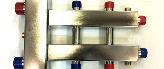
Factory manifold assembly
Let's first look at a specific example of what a ready-made distribution unit from the manufacturer consists of.
Table 1. Factory manifold assembly.
| Steps, photo | A comment |
| This collector assembly is called ready-made only because all the necessary elements, selected according to optimal parameters, have already been assembled. It itself is in a disassembled state, and all the parts still have to be put together. |
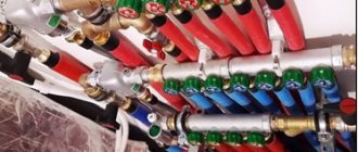
| This is a feed comb, each output of which is equipped with a flow meter (red device on top). Through it, the temperature range in the circuits is set. It is on this comb that, if necessary, the coolant supply to the circuits is shut off. |
| The return comb, unlike the feed comb, is equipped with push-action thermostatic shut-off valves. They are covered on top with caps, on the front side of which the direction of rotation (plus and minus) is indicated, by turning which you can adjust the feed manually. |
| Instead of a cap, you can install a servo drive on the valve, which will automatically regulate water flows. These devices are not included in the kit, but are purchased separately. |
| The desired temperature is set on the thermostat, and it already sends a signal to the servo drive. |
| The heating system is turned off using taps. |
| At the end of each collector, units are installed through which you can drain water from the system or bleed air. |
| We think there is no need to explain the purpose of the thermometer. |
| On the left side of the supply comb there is a hole through which heated water flows from the boiler. First, a tee with a thermometer is screwed onto it, and then a ball valve, through which the connection to the pipeline will be made. The same is done on the return line. |
| To the right, drain units are screwed onto both combs. |
| The manifold assembly kit includes a bracket, through which both combs are tied together and then hung on the wall. |
| The assembled unit is attached to the wall or installed in a special cabinet. |
| All that remains is to connect the supply pipeline and circuits to the manifold. |
Video - Manifold for underfloor heating and heating. Review, assembly and installation of the STOUT manifold block
An example of selecting an apartment distribution manifold
Let's consider an example of selecting an apartment collector according to the connection diagram shown in Fig. 3, that is, to four water points. Table 2 regulates the required flow rate at 0.28 l/s. Let the water supply to the house be made of a 1/2″ steel pipe (DN = 15 mm), allowing a flow rate of 0.29 l/s at a flow speed of up to 1.5 m/s. The supply to the “comb” is made with a metal-polymer pipe 20×2.0 (3/4″). According to the manufacturer’s data, we determine that the permissible flow rate through such a pipe is 0.3 l/s, which exceeds the capacity of the house inlet (1/2″). Having chosen the VTc.500NE collector with a nominal diameter of 1″ (DN = 30 mm), we check the general recommendations for choosing collectors (see above).
The cross-sectional areas of the “comb” (see Table 3) and the inlet (1/2″) differ by a factor of 4. With this ratio of nominal diameters, the reduction in losses along the length of the “comb” (formula 1) will be 23 times. This is not ideal (the ratio of the diameters of the comb and the supply is not :1, but 2:1), but in this case it is not critical: if the connection order is observed (see Fig. 3), the distribution manifold for water supply with 4 outlets will be able to fulfill its balancing role in dynamic mode of operation.
Large range of distribution manifolds
Table 3 shows, as an example, different numbers of outputs designed for connecting floor and apartment water supply and heating systems. In addition to water supply, these systems are suitable for both radiator heating and low-temperature systems, for example, “warm floors” and heating of open areas.
Table 3. VALTEC manifolds and manifold blocks
Distribution manifolds made of stainless steel, for example, VTc.510.SS, are becoming especially popular. They are successfully used in floor distribution units of water heating systems of typical multi-apartment buildings.
Views: 4,713
Collector design and principle of operation
The collector has the shape of a cylinder with holes drilled on the sides. Shutting devices are installed on the comb to regulate the pressure of the water flow. On the end side there is an inlet hole, the diameter of which is larger. It receives water from a water supply source.
There are internal and external threads on 2 sides of the device. Using a threaded connection, the device is connected to the main line, and, if necessary, to another collector. Connections are fixed on the sides, leading the system to different points of consumption. This system is called parallel.
In different cases, a shock absorber or plug is placed at the end of the device.
The distribution comb can have from 2 to 4 outlets. To supply water to a large number of points, several collectors are connected, and plugs are placed on the remaining holes.
Manifolds without taps
It is not always necessary in a house or apartment to regulate the flow of water in the pipes running from the water distribution to the plumbing fixtures. Moreover, with a small number of devices, it is not necessary to be able to turn off these devices individually.
In this case, you can get away from collectors with control valves and use a simplified collector water supply scheme, using collectors without taps.
The main function of such collectors - equalizing pressure in the distribution water supply system - will remain the same, but monitoring tasks will no longer be required.
For example, you have a large number of water consumers in your apartment: a washing machine, a water heater, a toilet, a kitchen sink, a shower in the bathroom, a sink in the bathroom, a shower in the toilet. With this or more consumers, a series (tee) circuit may not be effective and the use of several devices may be difficult.
If the apartment (house) has normal water pressure, then the simplest distribution manifolds without taps can solve the problem of comfortable use. They are not suitable for underfloor heating systems, but will do an excellent job in plumbing and heating.
Why do you need a collector?
The device equalizes the system parameters. Water supply manifolds perform the following functions:
- Regulate pressure. In tee wiring, the water pressure often decreases when several consumers use the water supply at the same time. The collector system avoids this; the pressure and temperature of the water in the taps are constant.
- During repair work or replacement of the mixer, the need to shut off the water supply along the entire riser disappears. Taps are installed at the outlets of the collector to regulate each branch.
- The wiring eliminates the presence of connections built into the wall. This reduces the likelihood of leaks. If fittings and taps fail, replacing them will not damage the cladding.
- If you need to introduce additional wiring, you do not need to change all the wiring. Connection takes little time and does not require the purchase of expensive parts.
The distributors have good hydraulic characteristics, are not subject to corrosion and can be installed without a special gasket. The advantages of a parallel water supply system are stability, practicality, isolation of each connection and the ability to adjust technical standards.
The high cost of wiring is the only drawback of the system.
Flaws
Despite the wide control possibilities, manifold heating distribution has not become widespread. And there are good reasons for this:
- Increased consumption of main pipes compared to conventional heating schemes. The more complex the building geometry, the more material needs to be purchased. Increased installation costs are also one of the significant reasons for low consumer demand.
- Traditional systems can be easily mounted on the wall in open or hidden versions. It is possible to lay a lot of lines from the comb only under the floor. Otherwise, you will get a very depressing picture, where heat mains will dominate the interior. And the material consumption for wall mounting will increase significantly.
- A prerequisite for installing the liner inside a concrete screed is the absence of joints. Each connection point is potentially dangerous from the point of view of breakthroughs. The prospect of destroying the foundation in order to eliminate a coolant leak looks depressing and requires a considerable investment of money, labor and time.
- The hydraulic resistance of a system with a mass of pipelines increases significantly. Especially if the diameter of the lines is small. Therefore, no gravity heating systems can even be considered. Only forced circulation of heated water.
- If you plan to use several independent heating circuits, then a circulation pump must be installed for each of them. Otherwise, the scheme simply will not work. Hence another item of additional costs.
- In any case, the system turns out to be energy-dependent, since it will not be able to function without a heating pump. Again, it’s a nuisance if for some reason there is no electricity. Or you will have to take care of an autonomous power supply.
All shortcomings ultimately come down to additional material costs. We can safely say that the collector wiring option cannot be classified as a budget solution.
Classic wiring diagram
In water supply systems, the traditional method of connecting consumers is a series or tee circuit. A common pipeline is laid from the riser, to which all devices are connected through tees and short supply pipelines.
The radiators of the heating system, if we talk about a parallel circuit, are connected in a similar way, only in addition to the distribution line there is also a “collection” line, that is, a return line.
Tee pipe layout
This method of organizing pipeline systems has two advantages:
- a minimum number of pipes are used;
- the circuit has low hydraulic resistance.
But using such a system is not very convenient. As soon as one of the household members opens the tap in the kitchen, the water pressure immediately drops, for example, in the shower cabin. In the case of a heating system, one has to deal with the problem of deteriorating coolant circulation through the radiators furthest from the heat generator.
Water supply to a private home can be organized either autonomously or through centralized networks. We will analyze the water supply scheme for a private house with a connection to the central main line or to an autonomous source in the article.
We will tell you here which septic tank is better to organize on a summer cottage.
And in this topic https://aquacomm.ru/vodosnabzenie/zagorodnyie-doma-v/avtonomnoe-vodosnabzhenie/trubyi/kak-sognut-profilnuyu-trubu-bez-trubogiba.html we will learn how to bend profile pipes without a pipe bender. Description of methods using improvised means.
General design principles
There is no uniform instruction for drawing up a detailed design of collector heating systems. In each individual case, heating devices and equipment are selected individually. But it will be useful for every interested person to familiarize himself with a few general tips.
The collector circuit is not for a city apartment.
An exception can be considered cases when builders in new houses additionally install one pair of valves in apartments, to which a heating circuit of any configuration can be connected. In this case, collector wiring is safely installed. With common risers for all apartments, a collector system is impossible.
Suppose there are several risers in the apartment and one or two heating devices are connected to each. You want a common collector circuit to be installed, and install a pair of combs on one riser with heat distribution throughout the apartment, disconnecting from all other risers. As a result, you will get a large difference in pressure and temperature of the “return” at your insertion. This will lead to the fact that the neighbors in the riser will have almost cold batteries in their apartments. As a result, a visit from a representative of the housing office is inevitable, who will draw up an act on illegal changes in the heating configuration and oblige you to make an expensive alteration of the heating system.
The system must be mounted so that the automatic air vent is located directly on the collectors. This is the best option, because sooner or later all the air in the circuit will pass through them.
The collector wiring system has many features, but some of them are also typical for other types of heating systems:
- The circuit must be equipped with an expansion tank, the volume of which must exceed 10% of the total coolant volume.
- The expansion tank is best placed in front of the circulation pump, on the “return”, in the direction of water movement. When using a hydraulic arrow, the circuit should be designed so that the tank is installed in front of the main pump, which circulates water in a small circuit.
- The choice of installation location for circulation pumps in each circuit is not important, but it is better to install them on the return flow. The operating temperature is lower here. The pump must be mounted so that the shaft is positioned strictly horizontally. Otherwise, at the first air bubble, the device will remain without lubrication and cooling.
Pipe selection
To determine which pipes are used to install the collector heating system, you need to understand the specifics of the collector wiring. Let's remember what can influence our choice:
- Pipes must be selected from those sold in coils. This allows you to avoid making connections in the wiring installed inside the screed.
- Pipes should not be afraid of corrosion and have a long service life. The reason is still the same: opening up the concrete floor to replace pipes is not part of our plans.
- The tensile strength and heat resistance of pipes is selected depending on the heating operating parameters. For radiators in a private house, the optimal parameters are 50 - 75°C water temperature and a pressure of 1.5 atm; for heated floors at the same pressure, 30 - 40°C is sufficient.
When a collector heating system is installed in apartment buildings, which is quite rare, the operating pressure should be 10 - 15 atm. at permissible water carrier temperature - 110 - 120°C. Based on these parameters, you have to make a choice of pipes.
It is necessary to install collector wiring when building a house. After laying the finished floor, installing this system will not be economically feasible, since the floors will have to be opened. Most often in this case, open wiring of heating systems is used.
Features and purpose
The manifold, also called a comb, in its simplest form is a piece of pipe with several pipes cut into it.
In pipeline systems, this element plays the role of a central distributor - devices or small sequences of them are connected to the pipes through pipes.
Such schemes are called collector or beam.
The main task of the collector is to ensure a uniform flow of medium to the devices and make the operation of each of them independent of the flow rate on other devices.
Different collectors may differ from each other in the following ways:
- Availability of additional equipment: manifolds are produced with shut-off and control valves, gearboxes, pressure gauges and even circulation pumps already installed on their pipes. The most modern modifications are equipped with sensors and automatic valves.
- Material: today both metal collectors (brass, steel, bronze and copper) and plastic (polypropylene) are used. Cheap silumin products (their unusually low weight gives them away) are not worth purchasing due to their low strength and fragility.
- Number of outlets (nozzles): usually collectors have 2 - 4 nozzles. But this should not limit the user: if necessary, several collectors can be combined into one, increasing the number of taps to the desired value.
- Maximum permissible pressure.
- Bandwidth.
- Center distance between branches.
Additional equipment is made from various materials. The quality of the collector and the maximum temperature of the working environment depend on their choice.
The principle of operation of the collector
As for the principle of operation of the collector, everything is quite simple. The heat generator that heats the water releases the liquid to the supply comb. At this intermediate node, the speed of the coolant flow slows down significantly, which is facilitated by a larger radius. This allows water to be distributed over several outlets.
Once you know how much coolant is consumed when heating an apartment (house) along all circuits, all that remains is to select the required power of the heat generator (boiler) and the speed of the fluid flow, after which the cross-sectional area will be known. When making calculations, be sure to convert liters to mm3.
When liquid enters a radiator or heated floor, it gradually gives up its heat, and then moves back along a different path, reaching the distribution unit of the collector block. Here the reverse comb is activated, directing the cooled coolant to the boiler or other generator for reheating.
Purpose and types
A warm water floor is distinguished by a large number of pipe circuits and a low temperature of the coolant circulating in them. Basically, heating the coolant to 35-40°C is required. The only boilers that can operate in this mode are condensing gas boilers. But they are rarely installed. All other types of boilers produce hotter water at the outlet. However, it cannot be run into the circuit at this temperature - a too hot floor is uncomfortable. To reduce the temperature, mixing units are needed. In them, in certain proportions, hot water from the supply and cooled water from the return pipeline are mixed. After which, through the manifold for the heated floor, it is supplied to the circuits.
Manifold for underfloor heating with mixing unit and circulation pump
To ensure that all circuits receive water at the same temperature, it is supplied to a heated floor comb - a device with one input and a number of outputs. Such a comb collects cooled water from the circuits, from where it enters the boiler inlet (and partially goes to the mixing unit). This device - supply and return combs - is also called a manifold for heated floors. It can come with a mixing unit, or maybe just combs without any additional “load”.
Materials
The manifold for heated floors is made of three materials:
- Of stainless steel. The most durable and expensive.
- Brass. Average price category. When using high-quality alloy, they last a very long time.
- Polypropylene. The cheapest. For working with low temperatures (as in this case), polypropylene is a good budget solution.
Manifold for underfloor heating with 6 circuits
During installation, the inputs of the heated floor circuits are connected to the supply comb of the manifold, and the loop outputs are connected to the return comb. They are connected in pairs to make adjustments easier.
Equipment
When installing a water heated floor, it is recommended to make all contours the same length. This is necessary so that the heat transfer from each loop is the same. It’s just a shame that this ideal option doesn’t come around very often. Much more often there are differences in length, and significant ones.
To equalize the heat transfer of all circuits, flow meters are installed on the supply comb, and control valves are installed on the return comb. Flow meters are devices with a transparent plastic cover with printed graduations. There is a float in the plastic case, which marks the speed at which the coolant moves in a given loop.
It is clear that the less coolant passes through, the cooler the room will be. To adjust the temperature regime, the flow rate on each circuit is changed. With this configuration of the manifold for heated floors, this is done manually using control valves installed on the return comb.
The flow rate is changed by turning the knob of the corresponding regulator (they are white in the photo above). To make it easier to navigate, when installing the collector unit, it is advisable to sign all the circuits.
Flow meters (right) and servos/servos (left)
This option is not bad, but you have to regulate the flow rate, and therefore the temperature, manually. This is not always convenient. To automate the adjustment, servo drives are installed at the inputs. They work in tandem with room thermostats. Depending on the situation, a command is sent to the servo drive to close or open the flow. In this way, maintaining the set temperature is automated.
Collector circuit
The collector distribution of water supply pipes in the house makes it possible to connect a large number of consumption points, including those located at a distance from the riser. The collector circuit is a parallel connection - each element (faucet, shower, toilet, bidet, etc.) is connected to the collector using an individual outlet equipped with a valve.
The advantages of the collector circuit are:
- constant pressure regardless of the number of plumbing fixtures turned on,
- easy detection of faults on each individual line,
- high reliability of communications due to the small number of connections in the system,
- the ability to shut off the water on the line requiring repair and maintain the ability to use other lines at the same time (for example, while repairing a shower, you can wash dishes, wash your face, etc.),
- collector wiring connection lines are easily hidden in boxes, niches, etc., ensuring an attractive appearance of the premises.
Collective distribution of water supply pipes in an apartment also has its disadvantages:
- its implementation requires a larger number of pipes,
- installation of parallel connections is more complex (if you plan to do it not yourself, but with the involvement of specialists, the complexity directly affects the cost of services).
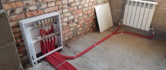
Collector layout of water supply pipes in an apartment
Collector layout of water supply pipes in an apartment allows you to optimize the operation of each device included in its composition. Filters or pressure regulators can easily be installed on individual outlets in accordance with the characteristics of water-consuming equipment and its requirements for operating conditions.
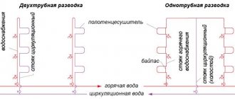
Comparison of collector and other types of wiring
You can choose one of 3 common pipe routing methods:
single-pipe heating - ideal for heating a small private house. In this case, all radiators are connected in series, which means that the last battery in the chain works less efficiently than the first. But the cost of such a scheme is minimal;
Single pipe heating system
with 2-pipe heating, the wiring diagram can be represented as 2 parallel circuits, one supplies hot coolant to heating devices, the second removes cooled coolant to the boiler. This heating method can be considered the most common;
Example of a two-pipe heating system
The collector wiring differs from the listed analogues in that each radiator is supplied with coolant individually. That is, a collector is installed in the room (its design is discussed later in the article), and from it a supply and discharge pipeline goes to each battery. This affects the cost and complexity of installation, but all the work can still be done with your own hands.
One of the pipe layout options
Of course, this does not have the best effect on the cost of installation work and materials. The total length of the pipes in this case will be maximum, and the collector also costs money (especially if the model chosen is not from the latest manufacturer with thermostats).
We manufacture a distribution manifold
We calculate the material required for the manufacture of the collector. The easiest way to do this is in Excel spreadsheets. At the same time, in this program you can calculate the cost of materials required for the manufacture of the device. We purchase the necessary starting material and prepare tools for self-production.
Preparing the tools
The starting materials for the main parts of the collector will be regular or square pipes. We make the necessary markings on them using calipers, a ruler and a core.
We make the necessary markings
Using a gas cutter, we make holes for the pipes.
Making holes for pipes
We insert the pipes (pipe sections with threads) into the seats.
Insert the pipes
We fix the pipes by welding. First, rough it out, and then scald it around the entire perimeter.
We fix the pipes by welding
We also weld brackets to the body for wall mounting.
We weld the brackets to the body
We clean the welding areas from scale and rust.
Cleaning the weld areas
We treat the entire structure with a degreasing compound and cover it with paint and varnish.
We treat with a degreasing composition, cover with paint and varnish
The paint completely sets in two to three days and we have a self-made distribution manifold at our disposal. Now all that remains is to install it in place and connect all the incoming and outgoing circuits to it.
Ready-made homemade distribution manifold
Advantages and disadvantages of the collector system
Separately, it should be noted the advantage of being able to connect consumers that are located at a remote distance from the riser. The presence of a valve on each outlet allows cutting off with lines, which is very convenient for repair and maintenance.
The advantages of collector wiring are considered:
- Constant water pressure and continuous supply in sufficient quantity.
- Ease of inspection to identify blockages and other pipeline faults.
- The minimum number of connections that are most susceptible to depressurization. There are no large number of tees, as in a series circuit, which is called tee wiring.
- The ability to locally shut off the pressure to carry out preventive and repair work when eliminating consumer breakdowns (washing machine, mixer, shower, bidet, bathtub, etc.). At the same time, you can use other instruments and devices.
To maintain the attractiveness of the interior, such wiring is hidden in a box with a hatch, through which the collector is serviced, the operating mode is monitored, and the outlets are closed. The remaining elements of the pipelines can be hidden in the walls or floor.
With all the advantages, there are also disadvantages:
- High price. More materials and fastening elements will be required. The number of pipes that will have to be spent during the installation process exceeds the minimum purchase volume, as is the case with a series connection.
- Difficult to install. It's not just about the work front. Already at the calculation stage, difficulties may arise. Of course, you can figure it out on your own, but hiring specialists is a clear advantage and a guarantee of the system’s effectiveness. True, the volume of work (as well as complexity) leads to an increase in the estimated cost.
But these shortcomings are covered by the fact that each outlet can be equipped with additional equipment necessary for the uninterrupted operation of equipment and plumbing fixtures. So, the check valve will save water in the boiler, the pressure switch will set the required mode, etc.
But all this will only work if the scheme is drawn up correctly. The manifold is connected to the riser (after the meter and the ball shut-off valve). A pipe leading to the consumer is connected to each outlet with a threaded connection. You can embed all the necessary additional equipment into it for efficient and safe operation.