A pipeline with reverse functioning is installed in apartment buildings for the purpose of heating and water supply. This complex design is necessary so that the water in the pipes moves in a circular motion and provides the residents with heat.
Reverse functioning pipeline
Installation of the system begins with installing a heating main into the house. Branches (two of them) are placed along the foundation from the nearest supply chamber. The branches carry hot water into the house. And the return, after heat transfer, “goes” to the boiler room or thermal power plant. At the entrance to the building there is a thermal chamber with shut-off valves or taps.
At the heating point (elevator unit), a temperature difference between the supplied and leaving water is ensured. Also, the supply of hot liquid to the hot water supply is organized there. Cleaning of the coolant and water contained in the system necessary for hot water supply is ensured.
Open heating system.
The easiest type of network to install and with acceptable efficiency. In addition, it has a fairly low price.
In the second case, the movement of the liquid will be determined by a number of physical laws and the angle of inclination of the pipes.
The operation of an open network consists of two stages that constantly follow each other:
- Supply of hot coolant from the boiler to all appliances.
- "Return." All excess liquid is sent to the expansion tank and cooled back into the boiler.
Scheme of an open heating system
In an open heating system, you can use both a single-pipe and a two-pipe heating scheme. In the first case, both processes occur in one pipeline, and in the second, supply and return are carried out in pipes separated from each other.
The simplest single-pipe open-type system includes the following parts:
- Boiler for heating the coolant.
- Heating devices (batteries)
- Open type expansion tank
- Pipeline
In a two-pipe open network, the pipeline footage has been increased due to the creation of separate supply and return circuits.
It is also worth choosing how circulation will occur throughout the entire system, either it will be natural circulation or a forced circuit with a circulation pump.
Circulation pump in the heating system
Considering the gravitational and forced open heating supply schemes, it is worth noting:
- With a gravity flow circuit, the circulation of the coolant occurs due to its expansion when heated. In addition, there must be an element such as an accelerating riser (its height must be more than 3.5 m). In the second type, a circulation pump is installed to increase the efficiency of the system. Under its influence, the fluid speed increases by 0.4-0.6 m/s and more uniform heating of the heating devices occurs. However, it is worth remembering that the operation of the pump is due to the presence of electricity.
- The use of a gravity system should be used in rooms up to 60 square meters. m. The recommended pipeline length is no more than 30 m. And the presence of an accelerating riser is required. The operating conditions of the compulsory scheme are not so strict. In addition, you can create a combined network in which, when the pump is turned off, gravity circulation will occur.
When installing an open heating system, you need to consider the following:
- For good coolant circulation, the boiler should be installed at the lowest point of the network (usually the basement), and the expansion tank as high as possible (usually the attic). However, you should not forget that in cold weather the attic must be insulated.
- The liquid level in the open expansion tank will constantly decrease as a result of its evaporation into the environment. As a result, air jams may appear, reducing the performance of the network. That is why it is necessary to constantly monitor its level.
- Since the system is open to evaporation of the coolant into the environment, for safety it is worth using only water (for example: antifreeze evaporation is toxic).
- Laying the pipeline should be done with a small number of turns and with a minimum of connecting elements.
- In winter, when the system is turned off, the water should be drained from it. To prevent damage.
Possible reasons why return pipes are cold or too hot
If there is insufficient heating of the premises, you should look for problems in the heating system, and it is useful to know how to determine the supply and return taps; the cold temperature of the latter indicates a malfunction in the heating circuit. In this case, the operation of all automatic systems and thermostats associated with responding to the temperature parameters of the output coolant is disrupted - this can lead to a malfunction of the entire system.
The main causes of cold return pipes are:
Installation errors. A similar situation can most likely occur when panel steel radiators that have two built-in terminals with a standard axial size are installed at the bottom using special units. In addition to the fact that their built-in radiator channels are designed to connect only their supply or return line, the correct operation of the units themselves becomes impossible if the pipes suitable for them are mixed up, the type of which is indicated by arrows on the device body.
Airing. The presence of air in any risers, pipelines or radiators leads to malfunctions of the system, in which an insufficient amount of coolant is supplied to the heat exchangers, as a result of which the temperature of the exiting liquid will be too low.
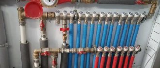
Rice. 14 Return pipeline in the collector distribution
Reducing the channel cross-section. In case of mechanical defects, contamination of the channels as a result of the use of hard water or expired antifreeze, in which the cross-section is narrowed, the volume of coolant entering the heater is too small and the return will have a low temperature. Often the narrow passage channels of shut-off plumbing fittings become clogged - in this case, the tap must be dismantled and cleaned with a means to remove lime deposits or other decomposition products.
Equipment breakdowns. Failure of the circulation pump will lead to the cessation of fluid flow, cooling of all circuits and cold return; this problem can occur from insufficient fluid flow in the line, which occurs when the circulation electric pump is faulty or insufficiently powerful. In case of mechanical damage or loosening of compression couplings, depressurization occurs, coolant leaks out and, accordingly, the entire system loses its functionality.
Technological reasons. In forced circuits, the movement of the coolant is carried out using an electric pump; when it is turned off due to lack of electricity, the movement of the liquid and the heating of the premises stop, the electric boiler also does not work and the batteries remain cold. If the supply of fuel to a gas heating boiler or diesel fuel is cut off, the house will also be left without heating.
Rice. 15 Violations when soldering polypropylene
Overfeeding
Reducing the flow helps to reduce the temperature of the return line, there are several reasons for this, in addition to clogging of the main passage due to contamination, narrowed channels in the places where the shut-off valves of control valves are located, in branches with connected auxiliary devices, such as liquid meters or thermostats, are often clogged.
In many cases, the determining factor for low flow is gross errors in installation, and you need to pay attention first of all to technology violations associated with soldering polypropylene pipes by inexperienced specialists. When the surfaces overheat during joining, the molten polyprolene is pressed into the pipe shell and the passage channel is narrowed, leading to insufficient heating of all heaters and a cold return.
If there are blockages, you will need to flush the system with hot liquid and resolder all joints if the polypropylene pipes are connected incorrectly.
Rice. 16 Clogged heating pipe
Poor coolant circulation
Poor circulation is often found in open gravity systems; it occurs when there is insufficient temperature difference between the medium at the inlet and outlet of the boiler. In a closed circuit, if operational problems arise, its low speed is associated with poor operation of the circular electric pump, clogging of the channel and fittings with limescale, and antifreeze decomposition products.
It may be necessary to flush parts of the system and drain the coolant; in case of severe contamination, individual devices (pump, hydraulic valve, three-way valve) are removed and cleaned separately. On the circulation pump, you should select a higher rotation speed of the electric motor shaft with an impeller (the standard device contains 2 or 3 speeds).
Return coolant overheating
Sometimes a situation arises when the average temperature of the return water is too high; this phenomenon can lead to a malfunction of the system, the mode of which is associated with measuring the temperature of the medium in the line. The main reasons for this phenomenon are too high a rate of water circulation through the heating circuit and flow through the bypasses of single-pipe systems connecting the supply and return pipelines. Since the carrier transfers heat with low efficiency, transferring it to radiators in too large a volume or bypassing them via the bypass jumper, this phenomenon leads to unjustifiably increased energy consumption and a decrease in the efficiency of the entire system.
To eliminate the negative consequences of overheating in a private house, reduce the rotation speed of the centrifugal wheel of the circulation pump, reduce the heating temperature of the working fluid, narrow the bypass passage channel, installing pipes of a smaller cross-section or installing control valves in each of them; similar operations with bypass are carried out in apartment buildings .
Rice. 17 How to choose a connection scheme from an efficiency point of view
To implement heating in private houses, one-pipe and two-pipe systems are used, the former are the most cost-effective, and the latter ensure uniform heating of all heat exchangers when using a Tichelman loop. It should be noted that the return of the heating system plays an important role: its correct installation increases the efficiency of the system, and temperature parameters are used in the operation of automatic devices that optimize heating and increase efficiency, as well as in identifying faults.
Single-pipe heating system with overhead wiring
Types of single-pipe heating with top wiring
In what cases is it important to install a two-pipe vertical heating system with overhead wiring? Most often, a similar scheme is applicable for small houses with an area of up to 100 m². Let's consider an example of organization for the most common system with natural coolant circulation.
Depending on the method of connecting the radiators, the heating scheme with top filling and natural circulation is divided into two types - with parallel and counter movement of the coolant.
Counter scheme
It is characterized by sequential connection of radiators and different directions of water movement in the main and return pipes. In this case, the heating system is single-pipe with overhead wiring, the design of which has a number of features, and is distinguished by the following parameters:
- Inability to adjust the degree of heating in each radiator;
- Dependence of heating of the coolant on the length of the pipeline. The further the radiator is installed from the boiler, the lower the temperature of the water entering it. To normalize the temperature in all rooms, batteries with a different number of sections should be installed;
- Compliance with the angle of inclination of the upper supply line. On average per 1 m.p. the inclination towards the movement of liquid should be 5-7 mm.
An expansion tank must be provided for top filling in the heating system. It is located at the highest point and performs several functions. The main thing is to stabilize the pressure when heating water in the pipes. If an open type tank is installed, coolant can be added through it.
You can increase the water pressure using an accelerating manifold - a vertical pipe installed immediately after the boiler. However, the minimum height of this element must be 3 m, which makes its installation in apartments impossible.
Associated movement of water
Connecting a radiator with bypass piping
In this case, the direction of movement of the hot and frozen coolant is the same. To improve the performance characteristics for the upper and lower heating distribution, experts recommend installing a bypass for each radiator. This is a straight piece of pipe connecting the inlet and outlet pipes of the radiator. The bypass package must include shut-off valves. As an additional control element, you can install a thermostat. In this case, not the entire volume of coolant may reach the battery. Adjustment is carried out using shut-off valves. Such a single-pipe heating scheme with overhead wiring has the following positive qualities:
- Ability to carry out repair work without stopping the system. To do this, the entire water flow is directed through the bypass;
- Installing a thermostat together with a three-way valve forms a system for automatically regulating the degree of heating of the radiator.
However, a heating system with overhead wiring and installed bass is more expensive than an ordinary flow one. This is due to the installation of additional materials and components.
Comparison with other types
In the lower insert, the supply line is laid from below, next to the return line, so the coolant is directed from the bottom up along the supply risers. Both types of distributions can be designed with one or more circuits, dead-end and associated flow of water in the supply and return pipes.
Natural circulation systems with connections at the bottom are used very rarely, since they require a large number of risers, and the point of inserting pipes in this way is to reduce their number to a minimum. Taking this into account, such structures most often have forced circulation.
Roof and floors - meaning
In the upper supply line, the supply line is above the radiator level. It is mounted in the attic, in the ceiling. The heated water flows to the top, then through the supply risers it evenly spreads over the radiators. Radiators must be located above the return line. To prevent air accumulation, install a compensating tank at the very top point (in the attic). Therefore, it is not suitable for houses with a flat roof without an attic.
The wiring from below has two pipes - supply and discharge - the heating radiators must be higher than them. It is very convenient for removing air pockets using Mayevsky taps. The supply line is located in the basement, in the basement, under the floor. The supply pipe must be higher than the return pipe. An additional slope of the line towards the boiler minimizes air pockets.
Both wirings are most effective in a vertical configuration, when the batteries are mounted on different floors or levels.
Self-assembly of a closed heating system in a private house?
To independently manufacture a closed-type heating circuit, you need to decide on the component elements and select the optimal wiring diagram.
Two-pipe or one-pipe heating scheme
As a rule, the circuit of a closed heating system can be one-pipe or two-pipe:
- Single-pipe wiring is characterized by low material consumption and ease of implementation. In this case, all heating devices are connected to the circuit in series. However, because of this, the coolant temperature in each subsequent device is lower than in the previous one. For this reason, a large house will warm up unevenly.
- In a two-pipe wiring, all batteries are connected in parallel, so a coolant with the same temperature circulates in each device, which ensures uniform heating of the house and each room.
The main disadvantage of two-pipe wiring is the complexity of design and installation, as well as the high consumption of materials. It is used in large houses with complex branched contours.
Choosing a boiler for a closed system
Since the closed-type circuit is equipped with a circulation pump, to heat the coolant you can use not a boiler, but a regular boiler, which is used to heat water for domestic purposes.
When choosing a suitable unit, consider the following:
- Heating device power. The choice of this parameter depends on the heating area. For every 10 m² of area, a heater power of 1 kW is required.
- Consider the parameters of the circulation equipment.
- The more branches in the heating system, the more powerful the boiler will be needed.
You can use instantaneous or storage water heaters. To drain the coolant, a drain valve is installed on the return pipeline. It is mounted on a tee with a ball valve.
To fill a closed heating system, one end of the hose is connected to the ball valve, and its other end is connected to a hand pump. If you need to pump ordinary water into the system, the water supply system is connected to the inlet pipe of the boiler. In this case, the coolant is drained through the drain valve.
Pros of independent systems
Already at the approach to the main consumers of the home water supply network, a whole range of preparatory measures is provided to ensure distribution, filtration and adjustment of coolant pressure. All loads fall not on the final equipment, but on the heat exchanger with a hydraulic tank, which directly receive resources from the main source. Such resource preparation is practically impossible on a private basis when operating dependent heating systems. Connecting an independent circuit also allows you to rationally use water for drinking needs for optimal purification. Streams are divided according to their intended purpose and each line can provide a separate level of preparation that meets technological requirements.
Operating principle of a two-pipe system
With a two-pipe heating system, along with the coolant supply pipeline, a return pipe is provided. Hot water flows to the radiators through supply risers. The waste coolant goes through the return risers into the return pipeline, through which it returns to the heating unit.
Due to the fact that hot coolant is supplied to each radiator individually in a two-pipe system, it is possible, if necessary, to turn off individual devices.
The scheme of a two-pipe heating system has two varieties, which differ from each other in the position of the supply line relative to the installation level of the radiators.
A two-pipe heating system with top wiring is characterized by the upper position of the supply pipe relative to the level of the radiators. With this scheme, a straight (supply) pipe is installed, as a rule, in the attic or in the ceiling. From the heating unit, the hot coolant rises up the main pipe, and then, through supply risers, is evenly distributed over the radiators.
The return pipe, through which the waste coolant returns to the boiler or other heating device, is located below the level of the radiators. The expansion tank is installed at the highest point of the system, usually in an insulated attic. This heating scheme is not suitable for cottages with a flat roof.
The main feature of a two-pipe heating system with bottom wiring is the laying of the supply line in the basement, under the floor, in the basement. The return pipeline, through which the coolant returns to the boiler, must be mounted even lower.
Air pockets from radiators are removed using Mayevsky taps.
Heating system with bottom wiring
Both types of wiring are applicable for both vertical and horizontal arrangement of coolant supply pipes. In a multi-storey building, a two-pipe system with a vertical position of the main pipeline, as a rule, has a lower distribution. This is explained by the fact that the thermal difference between the coolant in the forward and return pipelines creates significant pressure, which increases with increasing floor.
The lower distribution of heating pipes, thanks to this pressure, helps the coolant move through the pipeline. In this case, the upper wiring is used when it is impossible to install the lower one due to the architectural features of the building.
Main characteristics of two-pipe heating with bottom wiring
Despite its higher material consumption, compared to a single-pipe system, a two-pipe heating scheme with bottom wiring has a number of significant advantages:
- This type of heating allows you to avoid heat loss as much as possible, since the main main pipe runs in the basement or under the floor.
- This heating system can be put into operation immediately after the construction of the lower floor, without waiting for the construction of the entire house.
- The shut-off and control valves of the direct and return risers are located in the basement, which greatly facilitates its maintenance and makes it possible not to occupy the useful area of the building with utility systems.
- There is no need to turn off the heating of the lower floor when carrying out repair work on the upper floors.
- An important advantage of all types of two-pipe heating systems is the ability to install thermostats on each radiator, which allow heat regulation, thereby saving heating costs.
- The pipeline of a two-pipe system has a smaller diameter compared to a single-pipe system, so it does not spoil the appearance of the interior and, if desired, it can easily be hidden in wall or other building structures.
About installing additional units
As a rule, in a closed or open radiator heating system, where the heat source is a single boiler, it is enough to install one circulation pump. In more complex schemes, additional units are used for pumping water (there may be 2 or more of them). They are placed in the following cases:
- when more than one boiler installation is used to heat a private house;
- if a buffer tank is involved in the piping scheme;
- the heating system has several branches serving various consumers - radiators, heated floors and an indirect heating boiler;
- the same, using a hydraulic separator (hydraulic arrow);
- for organizing water circulation in underfloor heating circuits.
Correct wiring of several boilers operating on different types of fuel requires that each of them have its own pumping unit, as shown in the diagram for the joint connection of an electric and TT boiler. How it functions is described in our other article.
Connecting an electric and TT boiler with two pumping devices
In a circuit with a buffer tank, it is necessary to install an additional pump, because it involves at least 2 circulation circuits - boiler and heating.
The buffer tank divides the system into 2 circuits, although in practice there are more of them
A separate story is a complex heating scheme with several branches, implemented in large cottages with 2-4 floors. Here, from 3 to 8 pumping devices can be used (sometimes more), supplying coolant floor by floor and to different heating devices. An example of such a circuit is shown below.
Finally, a second circulation pump is installed when heating the house with water-heated floors. Together with the mixing unit, it performs the task of preparing coolant with a temperature of 35-45 ° C. The operating principle of the circuit presented below is clearly described in this material.
This pumping unit forces coolant to circulate through the heating circuits of underfloor heating.
Reminder. Sometimes pumping devices do not need to be installed for heating at all. The fact is that most electric and gas wall-mounted heat generators are equipped with their own pumping units built inside the housing.
What is the difference between heating flow and return?
And so, let’s summarize the differences between supply and return in heating:
- Supply – coolant that flows through water pipes from a heat source. This could be an individual boiler or central heating of the house.
- Return water is water that, having passed through all the heating radiators, goes back to the heat source. Therefore, at the input of the system there is supply, and at the output there is return.
- It also differs in temperature. The feed is hotter than the return.
- Installation method. The water conduit that is attached to the top of the battery is the supply; the one that connects to the bottom is the return line.
Greetings, dear reader! This is the first article on my website in which I will talk about two-pipe heating systems, because despite all the advantages of a one-pipe heating system (a relatively short length of pipelines and ease of installation), a two-pipe heating network is more often used for heating private houses.
This is due to a not very large, but quite convincing list of advantages of a system with a return and supply line. That is why, despite the complexity of the installation, it is installed most often if nothing interferes with the installation of such a system, for example, the architectural specifics of the house.
Classification
There are two types of units. The first type is “dry” pumps. In equipment of this type, the coolant and rotor do not interact with each other. The working part of the rotor is isolated and separated from the engine by stainless steel sealing rings. When started, the rings begin to move, a thin film of water seals the connections due to different pressures in the system and in the environment.
The efficiency of a “dry” unit is about 80%. This equipment is very sensitive to water contamination in the system, and if small particles get in, it quickly fails. The dry type pump is quite noisy, so when installing it, care should be taken to soundproof the room.
“Wet” pumps differ in their design from “dry” ones. Its impeller is located directly in the coolant. The stator and the moving part of the mechanism are separated by a special glass that provides waterproofing of the engine. “Wet” units are cheaper to operate and repair, and are quieter than “dry” units.
The disadvantages of “wet” type equipment include their low efficiency - only about 50%. This is due to the low sealing of the sleeve separating the stator and the coolant. Although even this performance is quite enough to heat any private home.
Adviсe
The expansion tank is located at or above the peak point of the main line. If there is an autonomous water supply, then it can be integrated with a supply tank. The slope of the supply and return pipes should be no more than 10 cm per 20 or more linear meters.
If the pipeline is at the front door, it is appropriate to divide it into two elbows. Then the wiring is created from the location of the highest point of the system. The lower line of a two-pipe structure must be symmetrical and parallel to the upper one.
All technological units must be equipped with taps, and it is advisable to insulate the supply pipe. It is also advisable to place the distribution tank in an insulated room. In this case, there should be no right angles, sharp breaks, which will subsequently create resistance and air pockets. Finally, we must not forget about the supports for the pipes - they must be made of steel and cut in every 1.2 meters.
Terminology
First, to avoid confusion, let's define the terms.
In addition: the elevator unit brings the pressure and temperature of the coolant to optimal values for the operation of the heating system. Thus, the difference between the supply and return lines of the highway reaches 4 kgf/cm2, while at the same time, a difference of 0.2 kgf/cm2 is sufficient to circulate water through the batteries.
So, what specific wiring diagrams for heating systems can be used in multi-apartment buildings? What specific elements do they include?
What is the difference between heating flow and return?
And so, let’s summarize the differences between supply and return in heating:
- Supply – coolant that flows through water pipes from a heat source. This could be an individual boiler or central heating of the house.
- Return water is water that, having passed through all the heating radiators, goes back to the heat source. Therefore, at the input of the system there is supply, and at the output there is return.
- It also differs in temperature. The feed is hotter than the return.
- Installation method. The water conduit that is attached to the top of the battery is the supply; the one that connects to the bottom is the return line.
If there is a large temperature difference between the boiler supply and return, the temperature on the walls of the boiler combustion chamber approaches the “dew point” temperature and condensation may form. It is known that during the combustion of fuel various gases are released, including CO 2; if this gas combines with the “dew” that has fallen on the walls of the boiler, an acid is formed that corrodes the “water jacket” of the boiler furnace. As a result, the boiler can quickly fail. To prevent dew, it is necessary to design the heating system so that the temperature difference between the supply and return is not too large. This is usually achieved by heating the return coolant and/or including a hot water supply boiler in the heating system with soft priority.
To heat the coolant between the return and the boiler supply, a bypass is made and a circulation pump is installed on it. The power of the recirculation pump is usually chosen as 1/3 of the power of the main circulation pump (sum of pumps) (Fig. 41). To prevent the main circulation pump from “pushing” the recirculation circuit in the opposite direction, a check valve is installed behind the recirculation pump.
Rice. 41. Return heating
Another way to heat the return is to install a hot water boiler in close proximity to the boiler. The boiler is “placed” on a short heating ring and positioned in such a way that hot water from the boiler after the main distribution manifold immediately enters the boiler, and from it returns back to the boiler. However, if the need for hot water is small, then both a recirculation ring with a pump and a heating ring with a boiler are installed in the heating system. With proper calculation, the recirculation pump ring can be replaced with a system with three- or four-way mixers (Fig. 42).
Rice. 42. Heating the return using three- or four-way mixers On the pages “Regulating equipment of heating systems” almost all technically significant devices and engineering solutions present in classic heating circuits were listed. When designing heating systems on real construction sites, they must be fully or partially included in the design of heating systems, but this does not mean that exactly the heating fittings that are indicated on these pages of the site should be included in a specific project. For example, at the recharge unit you can install shut-off valves with check valves built into them, or you can install these devices separately. Instead of mesh filters, you can install dirt filters. You can install an air separator on the supply pipelines, or you can not install it, but instead install automatic air vents in all problem areas. You can install a deslimer on the return line, or you can simply equip the collectors with drains. Adjustment of the coolant temperature for underfloor heating circuits can be done with qualitative adjustment using three- and four-way mixers, or quantitative adjustment can be made by installing a two-way valve with a thermostatic head. Circulation pumps can be installed on a common supply pipe or vice versa, on the return pipe. The number of pumps and their location may also vary.
When autumn confidently strides across the country, snow is flying above the Arctic Circle, and in the Urals night temperatures stay below 8 degrees, then the word form “heating season” sounds appropriate. People remember past winters and try to understand the normal temperature of the coolant in the heating system.
Prudent owners of individual buildings carefully inspect the valves and nozzles of boilers. By October 1, residents of an apartment building are waiting like Santa Claus for a plumber from the management company. The Lord of valves and valves brings warmth, and with it joy, fun and confidence in the future.
Where is the return route?
In short, the heating circuit consists of several important elements : a heating boiler, batteries and an expansion tank. In order for heat to flow through radiators, a coolant is needed: water or antifreeze . If the circuit is constructed correctly, the coolant heats up in the boiler, rises through the pipes, increasing its volume, and all excess ends up in the expansion tank.
Based on the fact that the batteries are filled with liquid, hot water displaces cold water , which, in turn, enters the boiler again for subsequent heating. Gradually the water temperature increases and reaches the desired temperature. circulation can be natural or gravitational , carried out using pumps.
Based on this, the return can be considered a coolant that has passed through the entire circuit, giving off heat, and, already cooled, returned to the boiler for subsequent heating.
Elevator with adjustable nozzle.
Now we just have to figure out how to more easily regulate the temperature at the elevator outlet. and is it possible to save heat using an elevator?
It is possible to save heat using a water jet elevator, for example, by lowering the room temperature at night. or during the day when most of us are at work. Although this issue is also controversial, we lowered the temperature, the building cooled down, therefore, in order to reheat it, the heat consumption must be increased against the norm. There is only one benefit: at a cool temperature of 18-19 degrees, you sleep better. our body feels more comfortable.
For heat saving purposes, a special water-jet elevator with an adjustable nozzle is used. Structurally, its design and, most importantly, the depth of quality adjustment can be different. Typically, the mixing coefficient of a water-jet elevator with an adjustable nozzle varies in the range from 2 to 5. As practice has shown, such adjustment limits are quite sufficient for all occasions. Danfoss offers circuits with control valves with a control range of up to 1 in 1000. Why this is used in a heating system is completely unclear to us. But the price ratio in favor of a water jet elevator with an adjustable nozzle relative to Danfoss regulators is approximately 1 to 3. True, we must pay tribute to Danfos, their products are more reliable, although not all of them; some varieties of inexpensive three-way valves do not work well on our water. Recommendation – you need to save wisely!
Fundamentally, all regulating elevators are designed in the same way. Their device is clearly visible in the figure. By clicking on the picture. You can see an animated image of the operation of the VARS control mechanism of a water-jet elevator.
And finally, a short comment - the use of water-jet elevators with an adjustable nozzle is especially effective in public and industrial buildings where it allows you to save up to 20-25% of heating costs by lowering the temperature in heated rooms at night and, especially, on weekends.
What else to read on the topic:
- Elevator unit with heat meter diagram
- Sample passport of thermal energy metering unit
- What is an elevator? Elevator heating unit –…
Bottlings
Depending on their placement, there are two heating distribution schemes.
Lower
Bottom filling, or a heating system with bottom wiring, is used in most modern buildings. Both the feed and return bottling stations are located in the basement. The risers are connected in pairs by jumpers located in the apartment on the top floor or in the attic; at the top point of each jumper there is an air vent (Mayevsky tap).
Any riser is a bridge between bottlings. The inevitable imbalance between the risers closest to the elevator unit and those farthest from it is compensated by the difference in the permeability and size of the pipes. Let us present the usual values of remote control for a heating circuit serving the entrance to a modern ten-story building.
| Plot | DU pipes |
| Spills near the elevator unit | 50 |
| Spills at end risers | 40 |
| Risers | 20-25 |
What specific advantages does bottom routing of heating pipes provide?
But: often basements are used for storage or utility rooms of stores. In this case, you yourself realize that there is no need to talk about any advantage: you will have to dump the risers through a hose into the sewer.
The main drawback of the lower wiring of heating systems is the complexity of starting them after the reset is completed. In order for circulation to begin through all risers, it is necessary to bleed off the air space. At the same time, not all residents of the upper apartments can do this; we should not forget about the empty premises.
Upper
Top filling, or heating with a top supply distribution, is completely and predictably different in that the filling supply thread is placed in the attic. The return remains in the basement. Any riser is a separate element, free from other risers.
In the attic, in addition to bottling the supply, in this case there are:
This heating system wiring scheme was widely used until approximately the 80s of the last century.
How does it look against the background of the bottom bottling?
It’s curious: a whole house heating system with an upper supply distribution is reset and started much more easily, especially if the discharge from the heating expansion tank is routed to the elevator unit. Alas: dumping a house is associated with the loss of a huge amount of coolant, which is undesirable from the standpoint of saving thermal energy.
Rules for installing a two-pipe heating system
- The slope of the pipes to the last battery in the circuit must be at least 0.5% (preferably 1%);
- The lower line must be laid parallel and symmetrically to the upper one;
- To facilitate operation and repair, radiators, bypass with pump, various technological units must be equipped with taps;
- The supply pipeline requires insulation to avoid loss of coolant temperature during its movement;
- In a system with overhead wiring, the expansion tank is installed in a pre-insulated attic space;
- When laying pipelines, right angles should be avoided, which create additional resistance. Overlaps should also be avoided, as air pockets will form in them;
- Supports for fastening the steel pipeline should be located every 1.2 m;
This is where I will finish the description of two-pipe systems. In the future, I will also consider single-pipe systems with top and bottom wiring; it also has its advantages compared to a two-pipe system, for example, metal consumption, etc. But about all this in new articles.
Most of the heating systems of apartment buildings and private buildings are built precisely according to this scheme. What are its advantages and are there any disadvantages?
Can a two-pipe heating system be installed with your own hands?
Vertical and horizontal schemes
Horizontal and vertical schemes differ in the location of the pipes that connect the heating devices into the heating system.
- Horizontal two-pipe system - more suitable for one-story buildings of large length. In this case, the most reasonable option is to connect heating devices to a pipeline laid horizontally. This scheme is convenient for arranging a panel-frame house or for a house without walls, where the risers are best located in the corridor or on the staircase.
- Vertical two-pipe system - differs in that the devices are connected to a vertical riser. Installation of such a circuit will cost more, but it is more profitable in operation, since there will be no problems with air locks. This scheme is suitable for a multi-storey building, because each floor is connected to the riser separately.
Both of these schemes are characterized by good hydraulic and thermal stability. Only for a horizontal scheme will it be necessary to balance the horizontal loops, and for a vertical scheme, balancing of the vertical risers will be necessary.
Providing heat to apartment buildings: centralized heating system
Published December 14, 2014 at 1:58 am
As is known, the provision of heat to a significant portion of the housing stock is carried out centrally. And, despite the fact that in recent years more modern heat supply schemes have appeared and are being implemented, central heating remains in demand, if not among owners, then among developers of multi-apartment housing. However, it should be noted that many years of foreign and domestic experience in using this heating option have proven its effectiveness and right to exist in the future, subject to trouble-free and high-quality operation of all elements.
Horizontal intra-apartment wiring
In many new buildings it is possible to find a relatively exotic scheme: outlets from risers enter the apartment, allowing heating devices to be installed to suit any layout. Along with this, the diameter of the risers and outlets is selected so that the horizontal contour in your apartment does not set the heating parameters in the apartments higher or lower.
In addition to an arbitrary layout, a horizontal circuit with an output and one input allows for the establishment of thermal energy metering. As the price of heating per square meter increases, the installation of meters becomes more and more urgent.
How to correctly install heating in the horizontal circuit of a separate apartment?
According to the author’s humble point of view, the most reasonable thing would be to adapt the Leningrad or barracks wiring diagram to this situation.
Where to put the boiler?
In a private house, in a one-story house, it is best to install heating boilers below the level of devices for heating the premises. In apartments the situation is somewhat different. Here, boilers are often placed on the same level as radiators, which is not entirely efficient. Therefore, it is better to install it as if in a pit, that is, place the equipment on the covering slabs.
To do this, the floor is usually cut out around the boiler. The “pit” should be made in compliance with fire safety rules. They involve leveling the base with a thin screed and laying sheets made of iron and asbestos. The boiler in the “pit” generates better circulation pressure.
Risers
The distribution of coolant through heating devices in a private house is possible horizontally and vertically (stand-up). In multi-apartment buildings in different areas, these schemes are side by side: if the bottling is always a horizontal layout, then the riser is a vertical layout.
What is useful to know about risers in an apartment building?
The heating system wiring is fully operational, but only with a huge (DN25) diameter of the connections.
Practical consequence: if you want to replace the interior wiring yourself, either use heating pipes of the same diameter, or throttle the jumper. The instructions are due to the fact that with a jumper diameter of 25 mm and connections with a nominal diameter of 15-20, the batteries will simply be cold.
From the laws of physics
Suppose that in radiators and a boiler the temperature of the liquid changes abruptly along the central axes: the upper parts contain hot liquid, and the lower parts contain cold liquid.
Hot water is less dense, which reduces its weight compared to cold water. As a result, the heating system consists of two communicating vessels, closed to each other, in which liquid moves from top to bottom.
The high column, formed by cooled water with a large weight, pushes out the low column upon reaching the radiators. As a result, the hot liquid is pushed and circulation occurs.
