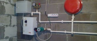
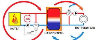
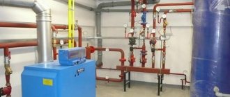
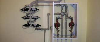
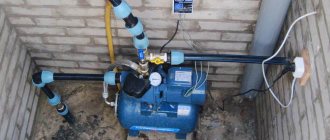
Autonomous heating systems in a private house can be open or closed, with gravitational and forced circulation of coolant. Closed-type schemes with forced water movement are considered optimal and more practical. Volatile heating lines ensure uniform supply of coolant to all devices without reducing the water heating temperature. But for the circuit to work uninterruptedly, you need automation for the heating circulation pump - what this is and why, you should understand in more detail.
How necessary is a thermostat for heating?
Scientific and technological progress allows us to take advantage of new products that improve our lives.
About 30 years ago, special devices began to be used in the heating system, with the help of which it is possible to control the temperature conditions indoors. Heating thermostats - as these devices are called - have become an integral part of any heating system, regardless of the purpose of the room where it is used. The novelty appealed to both specialists and ordinary people. Using thermostats, you can not only regulate the flow and temperature of the coolant in heating radiators, but also, if necessary, completely shut off the supply of the latter. This makes it easier to repair or replace the device, since there is no need to stop the entire heating process and completely drain the coolant. So this is an indispensable device in all respects. Therefore, installing a thermostat is a very worthwhile investment.
Connection diagram for electronic thermostats.
An electronic thermostat has an electronic circuit inside instead of a bimetallic plate. This electronic circuit requires a supply voltage. It can be equal to 220 or 24 volts and is supplied through a wire.
Here the control signal is the potential (voltage), which is supplied to the terminal box of the boiler or special hub. To make it clearer, look at the picture below:
From the picture you can see that there are not 2, but 3 wires going to the electronic thermostat:
- L—supply voltage.
- N - neutral wire.
- I is the output signal.
The unconnected port is used to enable the “night” operating mode, in which the room temperature is reduced by 4 degrees without adjusting the thermostats.
Electronic thermostats are used to organize complex climate control systems in the home; such systems are popularly called “Smart Home”. They can be used to control pumps and valve actuators in heating systems. You can see how this looks in the figure above.
Why do you need a pump in a heating system?
Circulation pumps for heating private houses are designed to create forced movement of coolant in the water circuit. After installing the equipment, the natural circulation of liquid in the system becomes impossible; the pumps will operate in constant mode. For this reason, high demands are placed on circulation equipment regarding:
- Productivity.
- Noise insulation.
- Reliability.
- Long service life.
A circulation pump is needed for “water floors”, as well as two- and one-pipe heating systems. In large buildings it is used for domestic hot water systems.
As practice shows, if you install the station in any system with natural coolant circulation, the heating efficiency and uniform heating along the entire length of the water circuit increases.
The only disadvantage of this solution is the dependence of the pumping equipment on electricity, but the problem, as a rule, is solved by connecting an uninterruptible power supply.
Installing a pump in the heating system of a private home is justified both when creating a new one and when modifying an existing heating system.
Operating principle of the circulation pump
The operation of circulation pumps increases the energy efficiency of the heating system by 40-50%. The operating principle of the devices, regardless of type and design, is as follows:
- The liquid enters a cavity made in the form of a shell.
- Inside the housing there is an impeller, a flywheel that creates pressure.
- The speed of the coolant increases and, through centrifugal force, the liquid is discharged into a spiral channel connected to the water circuit.
- The coolant enters the water heating circuit at a given speed. Due to the swirling of the water flows, the hydraulic resistance during fluid circulation is reduced.
The operating principle of a heating system with a circulation pump differs from circuits with natural circulation in that the fluid movement is forced. The heating efficiency is not affected by slopes, the number of installed radiators, or the diameter of the pipes.
The operation of circulation pumps may differ slightly depending on the type of design, but the principle of operation remains the same. Manufacturers offer more than hundreds of equipment models, with various performance and control parameters. Based on the characteristics of the pumps, stations can be divided into several groups:
- According to the type of rotor - to enhance the circulation of the coolant, models with a dry and wet rotor can be used. The designs differ in the location of the impeller and moving mechanisms in the housing. Thus, in models with a dry rotor, only the flywheel, which creates pressure, comes into contact with the coolant fluid. “Dry” models have high performance, but have several disadvantages: a high level of noise is created from the operation of the pump, and regular maintenance is required. For domestic use, it is better to use modules with a wet rotor. All moving parts, including bearings, are completely enclosed in a coolant medium that serves as a lubricant for the parts that bear the greatest load. The service life of a “wet” type water pump in a heating system is at least 7 years. There is no need for maintenance.
- By type of control - the traditional model of pumping equipment, most often installed in small domestic premises, has a mechanical regulator with three fixed speeds. Regulating the temperature in the house using a mechanical circulation pump is quite inconvenient. The modules are distinguished by high power consumption. The optimal pump has an electronic control unit. A room thermostat is built into the housing. The automation independently analyzes the temperature in the room, automatically changing the selected mode. Electricity consumption is reduced by 2-3 times.
There are other parameters that distinguish circulation equipment. But to choose a suitable model, it will be enough to know about the nuances listed above.
Tip 4 How to install a heating pump
- - sealant;
- — rubber or silicone gaskets;
- — a set of keys from “22” to “36”.
Select a pump for heating the room, taking into account its heat loss. The calculation should include heat losses of external walls, thermal conditions, i.e. what will be the average temperature in the building, the area of the room and other parameters. According to the theory, “heat flow depends on heat losses on external enclosures, which are directly proportional to the difference between the outside air temperature T1 and the indoor temperature T, the area S of the heated room, and the heat loss coefficient (W/m² K).” This calculation can be represented as follows:
- with a radiator heating system, if the area (S) of the room is 80-120 m², then the pump should produce 0.4 m³ of coolant per hour, with 120-160 m² - 0.5 m³;
- with a “warm floor” system, if S = 80-120 m² - 1.5 m³, with 120-160 m² - 2.0 m³.
Install the pump in a heating system with radiators on the return line near the boiler, where the temperature is lowest. In apartments and houses with an area of up to 200 m², this is quite conditional, since the coolant differs from the supply in the return pipe by 1-2 degrees. Therefore, in heating systems of small circuits, it does not matter where the pump is installed. The installation of a circulation pump for heating is carried out at the time of installation of the heating system; if it is operational, the coolant should be drained before this. You don’t have to do this if there are taps installed on the incoming and outgoing pipelines that block access to it. Then you should close them and begin the installation.
Install it in the direction indicated by the arrow on the body. It means the movement of coolant. A cleaning filter should be installed before entering the pump. Protect each threaded connection with sealant and gasket between mating parts. The pump must be installed strictly horizontally, otherwise the rotor can be damaged, and its constant “rumble” will be heard. After installing and filling it with coolant, open the central screw located on the top cover. Some liquid will come out of the hole. This will remove excess air from the pump. It can be connected to a 220V network either using a regular electrical plug, or through an electrical machine.
Connection diagram of the circulation pump to the electrical network
The connection diagram for the circulation pump to the electrical network is as follows:
Note. the pump connection diagram must contain either a differential circuit breaker (as in our diagram) or a combination of a protective circuit breaker and an RCD (Residual Current Device)
This is required, first of all, to protect a person from electric shock in the event of a pump malfunction or incorrect connection.
As you can see, there is nothing complicated in the circuit; to operate, a household circulation pump requires a phase and a zero (working zero), and in addition, an indispensable safety element is grounding (protective zero). Therefore, there are three contacts in the pump terminal box, with corresponding markings.
Detailed photo instructions for connecting the circulation pump to the electrical network, according to this diagram - HERE (link will open in a new window).
Most circulation pumps in heating systems are connected according to this standard scheme. The main disadvantage of which is that the pumps have to be turned on and off manually each time, so they are often turned on at the beginning of the heating season and turned off at the end. Disadvantages of this connection method. I think it is obvious that there is excess energy consumption and a decrease in the service life of the pump.
You can automate the operation of the circulation pump in the heating system in order to reduce energy costs and increase the overall service life of the pump by connecting it through a thermostat.
At the same time, the thermostat measures the temperature of the coolant and, if it is low, the circulation pump does not turn on, so as not to waste cold water (or other coolant) through the system, and when the temperature of the coolant at the boiler reaches the required level, the pump starts.
Diagram of the operation of a mechanical thermostat.
A mechanical room thermostat is the simplest version of a room thermostat, in which a circuit is closed or opened using a bimetallic plate. This thermostat does not require power supply. The scheme by which it works is as follows:
As can be seen from the diagram, there are two ways to connect such a thermostat;
- Via the NC terminal - connection for turning on air conditioners.
- Via the NO terminal - connection for gas and other boilers.
On the other side, you need to connect the wires to the terminal box on the boiler control board. In this case, you must first remove the jumper and secure the ends of the wires with screws.
This connection diagram is the simplest and is used on mechanical and electronic programmable thermostats. In this article I will talk about another scheme.
Operating principle
The operating principles of thermostats differ: for example, flow-through thermostats only block access to the coolant into the radiator circuit, while three- and four-way thermostats mix heated liquid with cooled liquid. Each thermostat has its own advantages and disadvantages. The installation of this device should be based on its operational characteristics.
In 1994, when construction companies, in accordance with the new SNiP, were required to equip heating systems with thermoregulating elements, only one enterprise in Kazan was engaged in the production of such devices. Today there are dozens of such manufacturers.
Two-way thermostats
The operating principle of these devices differs significantly from those described above. They are the same valve, only with two pipes - for connecting to the radiator and the coolant supply pipe. In this case, no mixing of coolants occurs. The temperature is reduced by shutting off the hot water supply in the circuit.
But can such devices be classified as thermostats? Most likely it is possible. Let's look at the design of a simple mechanical device.
It resembles a mechanical thermostat, but the liquid filler can be replaced with gas or spring filler. In both cases, the efficiency of responding to temperature changes is sharply reduced. But still this is a reaction without the presence of a person. In this design, the main move is to shut off the main coolant supply circuit and reduce its speed. This is precisely what the work of such a mechanism is based on.
Materials used in the production of circulation pumps
This is a very important aspect that affects not only the quality of work, but also the cost of the unit. It is clear without words that contact of pump parts and assemblies with water brings a lot of trouble. Therefore, for the production of this type, high-strength materials are used that can withstand water with a fairly high temperature.
For example, today analogs are produced where the shaft, that is, the rotor, and bearings are made of ceramics. Such parts have high strength and a long service life. In addition, ceramics are not afraid of water. Plus, such parts work silently.
The average guaranteed service life of circulation pumps is at least ten years. Of course, the manufacturers' requirements here must be strictly followed, otherwise there are no guarantees. What do manufacturers require? Correct selection, correct installation, prepared coolant, preventing some negative indicators in the heating system, for example, air inside.
Circulation pump connection
If the pump was not previously included in the heating system. it is required to be “inserted” into the pipeline. Since this operation requires the performer to have some skills and the presence of special equipment, it can be entrusted to professionals, or you can do the work yourself, having previously familiarized yourself with the technology of pipeline installation. The order of work and the list of equipment used will depend on the selected insertion method and pipeline material.
There are 2 ways to insert a circulation pump:
- on the main section of the pipeline;
- on the bypass section (bypass).
Installing the unit on the main site requires less time and money, but has one significant drawback. The pump operates from the mains power supply, so with this installation method, during a power outage in the apartment or house, the heating will not be able to function.
The second method is more complex, but provides the heating system with an increased level of autonomy. In this case, when the system operates in normal mode, the coolant moves through the bypass channel, and the corresponding section of the main line is closed using a specially installed ball valve. During a power outage, the faucet opens and liquid moves through the pipeline naturally.
Installation diagram of the pump on the bypass channel (bypass).
Although this option is common, it has one big drawback - the tap is on the main line. It is better if a ball valve is installed instead of a tap.
Installation of a pump on the supply of a gas floor boiler in a heating system with natural circulation. An article on the topic “How to choose a gas boiler” may be useful to you.
During normal operation, the valve is closed by excess pressure created by the pump above the ball. If the pump is de-energized, the ball rises under the pressure of water moving naturally along the line. This option is relevant if the pump is installed on the “supply” side for one reason or another.
Pump tap-in installation kit includes:
- pipes of the required diameter;
- elements of pipeline fittings;
- union nuts (for polypropylene pipelines) or bends (for steel pipes);
- dirt filter;
- shut-off valves;
- check valve
The diameter of the pipes for tapping must correspond to the diameter of the already installed pipeline, and their total length is determined based on the results of measurements in the area where the pump is intended to be installed. A set of pipeline fittings is selected in the same way. Union nuts (or clamps) are used for quick installation and removal of the pump.
The dirt filter is installed directly before the entrance to the unit. It is necessary to protect the pump from contamination, the source of which may be deposits on the inner surface of the pipelines. The drainage hole of the filter should be directed downward to allow periodic cleaning.
Shut-off valves are placed at the inlet of the pump in front of the filter and at the outlet of it so that, if necessary, the unit can be dismantled without stopping the entire system. When installing a supercharger in a bypass section, an additional valve is installed on the main line parallel to the pump. The check valve is designed to protect the system from water hammer. It is mounted at the outlet of the pump in front of the shut-off valve.
Preparing to install a heating pump
Before installing a pump, you need to buy it. A lot depends on the right choice.
Pumping equipment can be of different types.
There are many different models on the market from different manufacturers. You need to choose a heating pump whose characteristics correspond to the characteristics of the room, its area, the number of windows, external walls, etc. It is better to give preference to a more well-known manufacturer. You should not buy units that are too cheap due to the high probability of purchasing a fake. And when using such equipment, many problems can arise.
To simplify the process of installing a heating pump, it is better to choose a pump device with detachable threads. Otherwise, you will need to select adapters. But not every user will like this.
Additional equipment and tools for work will be needed:
- check valve Without it, the operation of the pressure pump will be ineffective;
- deep cleaning filter;
- shut-off valves;
- bypass from a pipe section. The diameter must correspond to the diameter of the riser;
- special keys for installation.
Power connection
The circulation pumps operate from a 220 V network. The connection is standard; a separate power supply line with a circuit breaker is desirable. The connection requires three wires - phase, neutral and ground.
Circulation pump electrical connection diagram
The connection to the network itself can be organized using a three-pin socket and plug. This connection method is used if the pump comes with a connected power wire. It can also be connected via a terminal block or directly with a cable to the terminals.
The terminals are located under a plastic cover. We remove it by unscrewing several bolts and find three connectors. They are usually labeled (the pictograms are N - neutral wire, L - phase, and “ground” has an international designation), so it’s hard to make a mistake.
Where to connect the power cable
Since the entire system depends on the performance of the circulation pump, it makes sense to make a backup power supply - install a stabilizer with connected batteries. With such a power supply system, everything will work for several days, since the pump itself and the boiler automation “pulls” electricity to a maximum of 250-300 W. But when organizing, you need to calculate everything and select the battery capacity. The disadvantage of such a system is the need to ensure that the batteries do not discharge.
How to connect a circulator to electricity through a stabilizer
Hello. My situation, a 25 x 60 pump is located immediately after a 6 kW electric boiler, then the line from a 40 mm pipe goes to the bathhouse (there are three steel radiators) and returns to the boiler; after the pump, a branch goes up, then 4 m, down, rings a house of 50 sq. m. m. through the kitchen, then through the bedroom, where it doubles, then the hall, where it triples and flows into the boiler return; in the bathhouse there is a branch 40 mm up, it leaves the bathhouse and enters the 2nd floor of a house of 40 sq. m. m. (there are two cast-iron radiators) and returns to the bathhouse in the return line; there was no heat on the second floor; the idea of installing a second pump in the bathhouse for supply after the branch; the total length of the pipeline is 125 m. How correct is the solution?
The idea is correct - the route is too long for one pump.
What is a circulation pump and why is it needed?
A circulation pump is a device that changes the speed of movement of a liquid medium without changing pressure. In heating systems it is installed for more efficient heating. In systems with forced circulation it is a mandatory element, in gravity systems it can be installed if it is necessary to increase the thermal power. Installing a circulation pump with several speeds makes it possible to change the amount of heat transferred depending on the outside temperature, thus maintaining a stable temperature in the room.
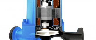
Cross-section of a circulation pump with a wet rotor
There are two types of such units - with a dry and wet rotor. Devices with a dry rotor have a high efficiency (about 80%), but are very noisy and require regular maintenance. Units with a wet rotor operate almost silently; with normal coolant quality, they can pump water without failure for more than 10 years. They have a lower efficiency (about 50%), but their characteristics are more than sufficient for heating any private home.
DS18S20
Update September 15, 2015. Added firmware for a two-speed pump
Update September 10, 2015. Added firmware for pic16F628A microcontroller
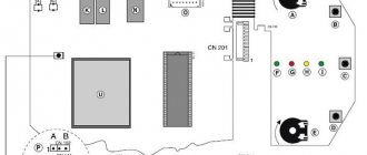
The device was initially assembled on a pic16f84a (pic16f628a) microcontroller. The DS1820 (DS18S20) sensor measures the temperature of the pipe at the boiler outlet. Depending on the temperature, the microcontroller turns the circulation pump on or off. Its main task is to turn on the circulation pump when the pipe is hot and turn it off when the pipe is cool.
To speed up the heating of the heating system when starting the boiler while the pipe is cold, by pressing the button you can switch the controller to manual mode for half an hour. In this case, the pump turns on when the pipe is cold. If the pipe does not warm up within half an hour, the controller goes into normal mode, turning off the pump.
When the temperature goes beyond the specified limits (less than +6 and more than +68 degrees), the controller sounds a sound signal and lights up the red LED. If the sensor breaks, a sound signal also sounds and the red LED lights up.
Simplified and schematically, this can be depicted as follows:
More information about the indication: LED1:
(temperature)
- off – temperature between 7 and 39
- green – temperature between 39 and 69
- yellow – temperature >69 or 6°C)
- 44H (68 => 34°C)
- 88H (136 => 68°C)
If you need to set other temperature thresholds, then you need to change these values. For example, you need to set the thresholds to 12, 45 and 75°C.
- 12 => 12*2=24 => 18H
- 45 => 45*2=90 => 5AH
- 75 => 75*2=150 => 96H
Thus, new values 18H, 5AH and 96H must be entered into the EEPROM cells before flashing.
Update:
In v2.2, the ability to select the temperature sensor type DS1820 or DS18B20 by setting the Jmp1 jumper has been added.
In final assembled form. The building cost half a kingdom.
Printed circuit board
Schematic diagram of switching on a two-speed pump. Nothing fundamentally changed in the basic design. A second node has been added (circled with a dotted line) to connect the high speed output of the pump. According to the logic of the controller’s operation, the second triac unit is turned on in the rapid heating mode. In normal mode, the second node is disabled and the first is enabled.
This scheme corresponds to firmware version 2.2.2
.
Firmware v2.2.2 has not been tested on a real device
Firmware
Version 2.2.2 for two-speed pump
Fuse configuration for pic16f628a 0x3FE9
In version 2.2.1, a bug in selecting a temperature sensor has been fixed. Firmware is available for two microcontrollers:
Fuse configuration for pic16f628a 0x3FE9
Version 2.2 added the ability to select a DS1820 or DS18B20 temperature sensor. DS18B20 is selected by installing jumper Jmp1. The firmware has not been tested in hardware. Subscribe, who will check.
Version 2.1 added the ability to set your own temperature values when flashing the firmware.
Version 2.0 fixed a small bug that only appeared when the temperature sensor was broken.
Varieties
Depending on the design, thermostats come with a built-in or remote sensor. The latter are convenient because they allow you to place the thermoelement and the control knob at a considerable distance from each other.
Classification by number of pipes
Based on the number of connected radiator pipes, they are divided into two-way, three-way and four-way. Two-way thermostats are also called walk-through thermostats. They have two outlets and are attached to only one pipe. A two-way regulator has a mechanical or electrical valve that partially or completely blocks the flow of coolant.
Heating systems equipped with three-way thermostats have great potential. The latter not only block access to hot water, but also supply cold water to the radiator circuit. As a result of mixing flows, the heating temperature of heating devices decreases.
It is important to install the three-way thermostat correctly. The manufacturer usually depicts the installation diagram on the device body
Blue color indicates the place for connecting the supply pipe with cooled coolant, red – with heated coolant, and the outlet location is marked with an arrow. The same applies to four-way models. True, unlike three-way regulators, they are capable of maintaining recirculation of cooled and heated coolants without mixing.
Classification by type of actuation
Depending on the method of actuation, thermostats are divided into two categories - manual and automatic. With the first ones, everything is simple: to reduce the flow of heated water or block its path into the radiator circuit, you need to turn the knob.
The second ones have a more complex design. They consist of a sensor and a thermostatic element built into a plastic housing. The sensor is filled with gas condensate, water or wax, which, when heated to a certain temperature, changes the volume of the medium. After this, the rod of the device begins to move, partially or completely closing the mechanical valve.
You can also install an electronic thermostat. It is equipped with an electrically operated valve. Depending on the principle of operation, electronic devices are:
- automated, which are triggered when the temperature recorded by the sensor changes;
- programmable, triggered in a user-specified period of time;
- radio-controlled, when the temperature of the heating radiator is controlled using a remote control.
Tip 3 How to connect heated floors to the boiler
The most economical and convenient option for heated floors is water floors with a connection to the boiler
. This system allows you to save a large amount of energy and makes it possible to independently regulate the heating temperature. In addition, it is easier to install.
- — wall-mounted boiler for heated floors;
- - collector cabinet;
- — shut-off valves;
- — compression fittings;
- - circulation pump;
- — thermostat (preferably, although not required).
Install heated floors in a sand-cement screed. To do this, prepare all the system components. Remove the existing screed and distribute all the elements of heated floors over the area where they are planned to be installed.
Then hang the boiler for heated floors in a convenient place - so that the loops of water pipes come from the collector. If you are installing floors in your own home, then it is advisable to place the equipment in a specially designated room. Regarding the installation of a boiler in an apartment, it is better to consult with an experienced technician.
Install the manifold cabinet. Its task is to circulate water in the pipes and combine floor heating with other home heating.
Place the supply and return pipes into the installed manifold cabinet. The first will supply hot water to the water floors. the second is to take the cooled liquid and return it back to the boiler. Install a shut-off valve on each pipe so that you can turn off the water if necessary.
Using a compression fitting, connect the pipe from the boiler to a metal valve, and connect the manifold inlet to the valve. Use fittings to connect the heated floor contours to the manifold.
Install a circulation pump in the collector designed to continuously circulate water. It is mounted on the supply pipe. It is better to purchase a pump with a thermostat. which will allow you to regulate the temperature of the floor heating.
After this, turn on the system and check its operation.
The final installation of heated floors is carried out only after the operation of the heating system has been checked. It should function for at least 10-12 hours. And, if everything is in order, the floor surface is laid over the pipes. Otherwise, there is a risk of flooding your own home due to a minor mistake. If the pipes are laid in a sand-cement screed, the system can be turned on only after the solution has completely hardened.
To avoid problems with connecting many different control devices, you can purchase a pump mixing circuit for wall-mounted boilers, which includes a circulation pump and almost the entire set of equipment.
- Installation of water heated floor
- how to connect a heated floor
What is a circulation pump
This is a small unit that is installed in the heating pipeline system and distils the coolant through all branches of the heating system, that is, it ensures the circulation of hot water. There is a wide variety of circulation pumps for heating systems. but for private houses, units with the so-called “wet rotor” are usually used. What is the design feature of this model?
The thing is that the moving parts of the pump, and this is mainly the rotor and impeller, are cooled and at the same time lubricated by the liquid flowing inside the pump, that is, the coolant. Hence the quiet operation, high reliability, and small dimensions of the unit itself. Let's add durability, efficiency and cost-effectiveness here.
Modern heat controllers TEPLOCOM TC for heating systems
Well-known Russian manufacturer of power supplies and automation devices, Bastion
produces a line of modern heating system controllers TEPLOCOM TC.
Description of the heating system controller TEPLOCOM TC-8Z
T EPLOCOM TC-8Z
heat controller is designed to control a multi-circuit heating system at home. The controller allows you to control the operation of the heating boiler, circulation pumps, and regulating shut-off devices.
The heat controller is capable of providing temperature control in all areas of your home. It has 8 control outputs, which makes it possible to control 8 independent heating zones. Using the TEPLOCOM TC-8Z
allows you to achieve significant savings in energy resources due to the ability to set different temperature conditions in different rooms of the house. The heat controller effectively controls the operation of the heating boiler and circulation pumps, which reduces the load on them and increases the service life of these devices.
TEPLOCOM TC-8Z controller
is a universal device and can work with heating boilers, circulation pumps, servo drives, thermostats from various manufacturers.
TEPLOCOM TC-8Z controller
It can be easily installed, does not require professional knowledge for programming, and has a clear indication of operating modes.
Advantages of the TEPLOCOM TC-8Z heating system controller
The TEPLOCOM TC-8Z heat controller has the following advantages:
- ability to control temperature in 8 independent zones;
- possibility of direct control of thermoelectric servos;
- support for devices with normally open or normally closed operating modes;
- the ability to turn off the heating boiler and circulation pump in certain operating modes;
- possibility of setting the delay value for turning on the heating boiler;
- the ability to set the delay value for turning on the circulation pumps of the heating system;
- regulation of the pump shutdown delay;
- indication of operating modes of the heating boiler, circulation pumps, servos and other actuators;
- increasing the efficiency of the heating system by installing separate heating modes for different rooms;
- simple device switching and easy installation.
TEPLOCOM TC controllers are reliable devices that provide effective control of the home heating system.
TEPLOCOM TC heat controllers can be connected to gas boilers and circulation pumps from various manufacturers.
The factory warranty period for TEPLOCOM thermal controllers is 5 years!
Advantages
Thermostats can reduce thermal energy costs by 10-20%. Those systems that not only have individual thermostats, but are also additionally equipped with regulators at the heating source, save 25-35% of thermal energy.
In addition, a pleasant microclimate is constantly maintained in the room, especially if automation is used to control the coolant.
Additional benefits
Other benefits of using temperature control devices include versatility and high accuracy. The versatility lies in the fact that thermostats are suitable for installation in heating systems of any type.
This equipment is used with gas, electric and solid fuel boilers.
High accuracy of adjustment is manifested in the fact that even a mechanical device stops the supply of heated water to the battery at the correctly calculated moment, not to mention devices with electronic filling.
The latter can be configured in such a way as to maintain a specific, comfortable temperature at certain hours. Often, an electronic thermostat even has a weekly programming function. The advantages also include the following qualities:
- durability - devices are made of corrosion-resistant steel. Particularly interesting is Russian-made equipment, which in terms of hydraulic and strength properties corresponds to domestic realities;
- a wide range of brands and models - today thermostats are manufactured by many companies and supplied from abroad. High competition allows you to reduce the cost of products.
Diagram and principle of operation of circulation pumps for heating
Structurally, the unit is a complex of main components and additional elements.
The supercharger circuit includes:
- Frame. Needed to protect the device from external influences.
- Box with terminals. Electrical components and adjustment devices are connected here.
- Electric motor. Puts the equipment into operation.
- Impeller. The part ensures the transportation of liquid through the pipeline at a given speed.
- Transfer chamber. The compartment is equipped with pressure and supply pipes for connection to the heating network circuits.
The principle of operation of the supercharger is simple:
- through the inlet pipe, water enters the pumping chamber;
- the coolant is picked up by the blades of the impeller, which begin to function when the engine is turned on;
- An increase in pressure sets the coolant in motion, water passes through the outlet pipe and enters the heating system line.
The circuit for the heating pump does not have any difficulties; the device works on the same principle as all blowers. The peculiarity lies in the correct choice of device depending on the type of heating network, design characteristics of the main line, boiler and heating devices.
Installation of Vilo pumps
Today, Vilo pumps are very popular on the market. They have good technical characteristics. A wide variety of sizes of threaded and flanged connections allows you to choose exactly the type of pumping equipment that is ideal for installation in an existing heating system. But the heating radiator itself will not be involved in the work.
It is worth considering how to connect the heating pump to Vilo. Installation of fork units is not difficult. The Wilo pump can be installed directly on the pipeline. There are different models. If the room has a small area (up to 750 sq.m), then you should give preference to the Wilo-Star-RS model. The pumps in this series are equipped with three-stage switches. For power supply, a current of 230 volts is required. The device can operate at a working fluid temperature from -10 to +110 degrees. In this case, the ambient temperature should be no more than +40 degrees.
Installation of this unit involves horizontal placement of its shaft. The terminal box has two cable outlets. Therefore, the Wilo heating pump can be connected to the electrical network from any side. Thanks to the spring-loaded terminals, the cable is connected very easily.
Thus, connecting a heating pump is not a difficult job. And you can do it yourself. The main thing is to choose the right pumping equipment, know the installation features and follow a number of rules when installing the device.
Automatic control unit for circulation pump
The circulation pump is controlled by a thermostat, relay, and uninterruptible power supply. The complex is needed to regulate the heating of the coolant and maintain the operation of the equipment.
Thermostats
The units combine the functions of a thermoelement and a valve; they are needed to adjust the water heating temperature.
The thermostat for the heating circulation pump works like this:
- Reads information from the temperature sensor. Compares indicators with settings. To set the settings mode, there is a side menu with a difference between the pump start temperature and hysteresis. Hysteresis is the time interval of temperature lag when the heater is turned on and off.
- When the equipment is started, hysteresis is automatically added to the water heating indicator when the blower is turned on. When the pump is turned off, the hysteresis is subtracted from the total value.
By default, the hysteresis size is taken to be 1/10 of the coolant heating temperature. Thus, when the water is heated at +50 C, the hysteresis is only 5 degrees. For the automatic control unit to start working, the water must warm up to +55 C. To turn off the unit, it must cool to +45 C. Units with hysteresis are more convenient to use. The equipment maintains a temperature rise of 5 degrees, therefore it is protected from constant switching on/off.
The thermostat should be selected with a firmware hysteresis of at least +/- 1 degree, maximum +/- 10 degrees. Place a thermostat next to the boiler. Provided that it is adjusted taking into account the external temperature in the room, the boiler adjustment should be able to change the media indicator.
Uninterruptible power supply
The heating circulation pump control unit is a volatile equipment and will not work without electricity. A UPS (uninterruptible power supply) or generator will eliminate the possibility of downtime. It is permissible to do without a power supply device, starting the network in gravity mode. But there is a risk of errors in pipeline layout, which will lead to network failure.
The contours of the gravity heating network, according to the laying technique, are inclined towards the return circulation pipe. It is recommended to maintain the slope within 3 cm for each meter of pipeline. This requires accurate calculations of the circuit and increases the network layout area.
The return circulation line is mounted with a slope towards the heater, also taking into account the slope. If the level of reduction is small, there is a risk of coolant stagnation and the formation of an air lock. In addition, the heater should be installed at the lowest point of the circuit, which causes difficulties in the absence of a basement.
A circulation pump will help to avoid all problems; to provide it with power, a UPS or generator is built into the network. The choice depends on the user, but the generator makes a lot of noise during operation, while the uninterruptible power supply operates as quietly as possible.
On/off relay
This is a module for starting equipment into operation and turning off the unit. The heating pump activation relay is an important component responsible for maintaining the functionality of the entire unit.
The task of the unit is simple:
- a decrease in the pressure level in the network is a signal to start the device into operation, the relay turns on the equipment;
- exceeding the established pressure norm is a signal to stop the equipment.
Thus, when the coolant collection stops and the pressure in the network increases, the timer for the heating pump switches off. Resuming the extraction of hot water leads to a decrease in the pressure indicator and puts the device into operation. Whether or not to install a thermostat or UPS is up to the owner.
A high-quality circulation pump with a temperature sensor has a number of advantages:
- reduces fuel consumption;
- ensures maintenance of a comfortable temperature in the premises;
- makes it possible to quickly adjust the operating mode.
Experts recommend choosing devices in accordance with the manufacturers' instructions. Manufacturers of equipment without an automatic control unit indicate in the technical data sheet the parameters of the unit suitable for installation on the devices.
To simplify the regulation of water flow in the battery, it is recommended to equip all batteries in the house with thermostats. When choosing them, you need to take into account the gradations of the settings - the smaller the divisions, the more accurate the mode. It is more practical to take devices with a scale gradation of up to 5 degrees.
Controller for boiler circulation pump KG CS-07
The KG CS-07 controller is designed to control the pump that circulates water in the central heating system. The regulator's job is to turn on the pump if the temperature exceeds the value you set, as well as turn it off if the boiler cools down (as a result of extinguishing). This avoids unnecessary pump operation, which saves energy (depending on the degree of use of the boiler, savings can be even 60%), and also extends the service life of the pump. Thanks to this, the reliability of the pump increases and the costs associated with its operation are reduced. The thermostat is equipped with an anti-stop system. Another useful feature is the beep sound, which indicates that the temperature is too high. The signal starts when the temperature at the point where the sensor is installed exceeds (90 ° C). The thermostat is also equipped with an anti-freeze system and turns on the pump when the temperature drops below 5 degrees C. Below this temperature, the pump runs all the time.
Power: 230/50Hz +/-10% Power Consumption: 2W Ambient Temperature: -10 to 50°C Pump Output Load: 6 Temperature Measuring Range: 0 to 99°C Adjustable Temperature Range: 5 to 80 °C Temperature sensor strength: -10 to 120 °C Sensor cable length: 1.2m
Thermostat CS-07C
The CS-07C thermostat can be used as a thermostat or underfloor heating pump controller. The device can regulate the temperature of turning the pump on and off. The pump turns on when the user-set temperature (O) is exceeded and will turn off when the user-set temperature (U) is reached. CS-07C is equipped with an anti-stop function that prevents the pump from sticking outside the heating season every 14 days for approximately 15 seconds. Another useful feature of the controller is an audible alarm that signals when the temperature is too high. The signal appears when the temperature in the place where the sensor is installed exceeds (90 degrees C). The controller is also equipped with frost protection and starts the pump if the temperature drops below 5°C; below this temperature the pump runs all the time. Power: 230/50Hz +/-10% Power Consumption: 2W Ambient Temperature: -10 to 50°C Temperature Measuring Range: 0 to 99°C Adjustable Temperature Range: 10 to 75°C Temperature Sensor Strength: -10 to 120°
Instructions for the boiler pump controller can be downloaded below in the specifications section
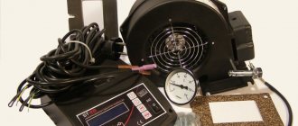
Boiler fan:
In some models of pyrolysis or conventional solid fuel boilers, it is convenient to use forced air exhaust fans and smoke exhausters. From the Polish manufacturer MplusM, they are represented by the series RR 152-3030 LH, R2E 150 AN91-06, R2E 180 CG 82-05+kond, R2E 210 AA 34-05+KPL. You can find out the cost of MplusM smoke exhausters with different characteristics by clicking on the link below.
To control the boiler in automatic mode, according to the specified parameters of temperature, time, etc., a control unit or controller must be connected to the fan. This device, with a built-in microprocessor, will control the operation of a boost fan or smoke exhauster, according to specified programs in the database or based on user settings. All controllers for fans or smoke exhausters are equipped with several factory programs for controlling fan operation. Some of them have advanced functionality. You can not only set the time for turning the fan on and off based on the coolant temperature, but also set the fan speed (boost power) at each stage of the heating boiler operation. The most popular controller models: ATOS, Comfort Eco, KG Elektronik CS-19. The price of boiler controllers depends on the quantity in the order.
For example, the price of the control unit is
For the undemanding buyer or those with limited financial resources, manufacturers produce budget versions of kits for connecting to the boiler (fan + controller). These kits are affordable but limited in functionality. For example: Boiler control unit PK 22+fan NWS 75
Functional purpose of thermostats
In most cases, during heating operation, uneven heat distribution in radiators and pipes is observed. This is due to its cooling while moving along transport routes. For stabilization and timely adjustment, room thermostats for heating are installed.
Controlling the degree of heating of the radiator. By regulating the flow of hot water, the temperature on the surface of the heating device changes;
Optimization of coolant heating costs. An overhead thermostat for heating reduces the cost of heating hot water by reducing the difference in coolant temperature between the supply and return pipes;
Automation of heating operation. Almost all models of temperature control devices operate autonomously
It is important to initially correctly set the initial operating parameters.
How does a thermostat for a heating boiler differ from a similar model for a radiator or circulation pump? First of all, the response speed of the control element and the operating temperature. Therefore, it is recommended to select the optimal model for each heating component. And to do this, you should consider their types and design features.
Any thermostat for heating a home has individual operating parameters - installation features, degree of temperature control, etc. They must correspond to the characteristics of the heating element on which the device will be installed.
Wireless thermostat connection diagram.
At the moment, wireless thermostats have become widespread and have seriously displaced their wired counterparts. They are easier to work with; you don’t need to run wires from the thermostat to the sensor across the entire house. It is enough to simply set the address of the sensor and install it in a place with stable reception of the signal from the thermostat. As for the connection diagrams for such devices, there can be two of them:
Open circuit connection diagram.
The diagram is no different from the connection diagram for a mechanical thermostat. The boiler, pump or servo drive is turned on when current appears in the circuit.
Connection diagram based on potential (voltage).
In this circuit, when the circuit is connected, the thermostat transmits a voltage to the boiler input, which turns on the boiler, pump or servo drive.
Installation of a thermostat
Before installing the thermostat, you need to make sure that it is compatible with the heating system. Each device has its own valve capacity coefficients, denoted Kv and Kvs.
It is recommended to equip single-pipe systems with thermostats with a Kv value greater than 1, and even better - greater than 1.5. For two-pipe regulators, regulators with Kv in the range from 0.5 to 0.9% are more suitable.
Sequence of work
The sequence of installation work is as follows:
- after shutting off the supply riser, water is drained from the heating system;
- horizontal pipe connections are cut off at a short distance from the battery;
- disconnect the cut section of the pipeline along with the valves;
- if the system is single-pipe, a bypass is welded. This is a jumper that will allow coolant to circulate through the circuit when the valves are closed and there is no access to the battery. In two-pipe heating systems, the thermostat is mounted on the upper supply pipe, and the valve is mounted on the lower;
- remove the shanks with nuts from the shut-off valve and thermostat, and then screw them into the radiator plugs;
- The piping is assembled and installed, and then connected to the horizontal supply pipes.
Location nuances
The axis of the thermal head should always be located in a horizontal position so that the temperature measurement accuracy of the device is high.
In a vertical position, the sensor will be exposed to rising and falling heat flows, causing temperature readings to be incorrect.
If the rod axis is mounted vertically, it is better to use a remote electronic sensor with an electric drive or with radio signal transmission.
Thermostats that have a built-in sensor must be positioned so that they are visible, but not within the range of operation of heating devices. Also note that heat is shielded by thick curtains. The optimal height for placing the thermostat is at least 80 cm from the floor surface.
It is allowed to install thermostats on bimetallic, steel and aluminum batteries. If the radiator body is cast from cast iron, it is not recommended to install a thermostat due to the high inertness of this alloy.
What wire can be used to connect room thermostats?
Another important point in connecting the thermostat is the choice of wire. Typically, the cross-section and number of cores are indicated in the instructions for a specific product. In addition, you need to remember the distance from the thermostat to the boiler or hub to which the thermostat is connected - if the output on the thermostat is potential, then the length of the wire can have a significant impact on the operation of the automation. This is due to the voltage drop on the wire. To reduce it, you should take a wire with the largest possible cross-section.
Most often, to connect mechanical thermostats, a two-core wire with a cross-section of 0.5 or 0.75 “squares” is used . For electronic ones, as I described above, it is important to consider the length of the wire. The longer the wire, the larger the cross-section should be (usually the cross-section does not exceed 1.5 “squares”) . But manufacturers do not recommend exceeding the wire length of 100 meters, although this is not specified in the data sheets and instructions for the products.
