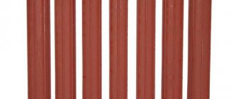
Ilya Platonovich, Kazan asks a question: Hello. Help solve the problem. I want to install a heating system in a private house, but I don’t know whether it is necessary to maintain the slope of the pipes.
It is important that the house warms up well and there are no problems due to air locks. What slope of heating pipes will be optimal for high-quality and efficient operation of the system? There are no plans to install a pump, but it is desirable that this does not affect the quality heating of the house.
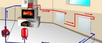
I would like to get professional advice from a specialist to avoid mistakes during installation. The expert answers: Heating with natural circulation does not require the use of additional equipment. It is most often used for heating dachas, cottages and country houses, if the radius of the circuit does not exceed 30 m. Advantages: cost-effectiveness, simple installation and operation. The natural circulation system includes a boiler, pipeline, radiators, and expansion tank.
The main characteristics of heating pipes: diameter, material of manufacture, slope. The correct choice of pipeline slope allows for rapid movement of water from the boiler to the devices and removal of air. The water supply and return lines must have a slope in the direction of water movement of at least 10 mm per 1 m of pipe. Without a slope, heating with natural circulation may not work, because the pressure in such systems is insignificant. The slope allows you to get rid of air pockets, increase heat transfer, reduce the load on the boiler, reduce costs, and increase the service life of the heating unit. If the slope of sewer pipes according to sanitary standards is 2 cm per 1 m, then for heating lines it should be at least 5-10 mm .The circulation speed is determined by a number of factors: pressure, diameter and material of the pipes, the number and radius of turns, the presence, type and quantity of shut-off valves. The main conditions for choosing the slope of heating pipes: ensuring good coolant circulation due to a slope of 10 mm per 1 m of the pipeline and high-quality installation using special devices - spirit level or hydraulic level.
If the horizontal outlet has a length of less than 0.5 m, you don’t have to arrange a slope. The layout can be top or bottom, but for any scheme it is better if the heating unit is located below the level of the pipes. The circulation pressure depends on the difference in height between the lower radiator and the boiler, and the lower it is, the faster the water will flow into it by gravity. It is impossible to make an exact calculation, but if you take into account the recommendations, the heating in the house will be efficient and of high quality. Natural heating warms up slowly, but also cools down slowly, and this is a huge plus in winter. Installing a complex of devices is a difficult task, and it is better to entrust the work to professionals, but if the house is small, you can save money and do the work yourself. Share a useful article: Similar articles:
One of the main stages of planning a heating system in a house or apartment is the calculation of heating pipes. At this stage of project development, the type of pipes, as well as their diameter, are determined. The duration and quality of its operation will depend on the correct selection of all the starting materials for creating the heating system.
Correctly selected and installed heating pipes will ensure minimal heat loss and uninterrupted operation of the system
Strengths and weaknesses of single pipe systems
The popularity of single-pipe heating in private construction is explained by the fairly low cost of the structure and the ability to independently carry out installation work.
This makes it possible to save on hiring specialists. Among other advantages of single-pipe systems, the following should be highlighted:
- High level of hydraulic stability. If you turn off some of the circuits, this will not affect the heat transfer of the remaining elements of the system. The same applies to replacing batteries or increasing the number of their sections.
- Low pipe consumption for organizing a main line.
- Slight inertia. To heat up the system, an order of magnitude less coolant is required than in schemes with two pipes.
- External aesthetics. Installation of a single-pipe system usually does not affect the beauty of the interior of the room, especially when using hidden laying of the main pipe.
- Thanks to the use of innovative shut-off valves (automatic and manual thermostats), it is possible to fine-tune the operating modes of the heating circuit and its constituent devices.
- Simplicity and reliability of the design, which makes it possible to install a single-pipe heating system on your own. The same applies to heating maintenance during operation.
By organizing the connection of control and monitoring devices for the heating system, it is possible to achieve its functioning in automatic mode. Integration into the Smart Home system is also allowed: as a result, it becomes possible to program optimal heating modes, taking into account the time of day, season, etc.
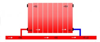
The main disadvantage of a single-pipe heating scheme is the presence of an imbalance between the heating of the radiators, depending on their distance from the boiler. This is explained by the gradual cooling of the coolant as it circulates through the pipes. As a result, the batteries closest along the coolant path turn out to be hotter than those located further away. In such cases, it is better to use cast iron devices, which are characterized by slow cooling.
Diameters of heating pipes and features of their selection
When starting to solve such a problem as calculating the diameter of heating system pipes, you should take into account that there are several concepts united by the general term “pipe diameter”. Each pipe can be characterized by the following parameters:
The internal diameter is the main characteristic of a pipe, indicating its throughput capacity. The external diameter is an equally important characteristic that must be taken into account when designing a heating system. Nominal diameter (nominal diameter) is a certain rounded value that is indicated during marking. We should also not forget that pipes made from different materials have a number in their markings corresponding to one or another of its diameters:
We should also not forget that pipes made from different materials have a number in their markings corresponding to one or another of its diameters:
- Steel and cast iron pipes are marked by the size of their internal diameter. Pipes made of copper or plastic are marked by the size of the outer diameter.
That is why, when calculating the cross-section of a heating pipe, it is imperative to take into account the material of the pipes. Especially if you plan to create a system that is a combination of different pipes.
One of the features that influences the choice of size of any pipes is the unit of measurement adopted to estimate the size of their diameter, and therefore their marking. The basic unit indicating pipe size is a whole number or fraction of an inch. To convert inches to our usual measurement system, remember that 1 inch = 25.4 mm.
Rules for calculating tank capacity
Any type of dilator will be effective only if the volume is chosen correctly. To do this, take into account the ability of the liquid to expand during the heating period. Water in heating rings expands by at least 3% of the total volume of the water system, antifreeze - by almost 5%.
Liquids belong to the category of incompressible media, so the tank must provide them with a sufficient reserve for thermal expansion with some margin. Provided that the circuit is completely filled with coolant, even thermal expansion in the calculated volumes can lead to liquid discharge through the safety valve and spillage of coolant onto the floor.
Therefore, so that exceeding the volume of expanding coolant does not lead to accidents, closed tanks for small circuits in private houses are purchased so that their volume is equal to 10% of the total volume of coolant circulating through the system. This rule is valid for systems with a capacity of up to 150 l.
If more than 150 liters of coolant moves along the heating ring, then the capacity of a closed tank is calculated by multiplying the total volume of liquid by its expansion coefficient at specific operating temperatures in the system.
To the obtained value you need to add the size of the water seal, i.e. the volume of coolant formed in the tank as a result of standard static fluid pressure. For large heating rings, this figure is usually equal to 0.5% of the total coolant volume; for small ones, with a capacity of up to 150 liters, it is taken to be 20%.
The resulting amount is multiplied by a correction factor determined from the values of preliminary and final pressure in the heating system. The preliminary estimate is that there is 1 bar per 10 m of contour height. The final pressure is formed as a result of the operation of the system.
Calculation of the volume of a closed tank for large complex heating structures looks like this:
The calculations used: Vn – nominal volume of a closed tank; Ve is the volume of the coolant during thermal expansion (calculated using the formula Vsystem×n%, where n is the coefficient of thermal expansion of the coolant); Vv – water seal; po – preliminary pressure; pe – final pressure indicator, equal to the maximum pressure value of the safety valve minus 0.5 bar
Open type capacity is not strictly regulated by regulations, but there is a rule: the volume of the open tank to the overflow pipe should be 3.5 - 4% of the total volume of coolant in the heating circuit.
This estimate is sufficient for a small country house, but a building for permanent residence will require a more accurate calculation. First of all, you will need to find out the total volume of the heating system.
Options for calculating the total heating capacity
This indicator can be determined with varying degrees of accuracy in three main ways. Firstly, based on the boiler’s passport data. Thus, about 15 liters of liquid are needed per unit of boiler equipment power. To obtain the necessary data, you will need to multiply 15 by the boiler power indicated in the data sheet.
Secondly, you can find out the volume using a water meter when filling the system. As you fill, the amount of liquid used is taken into account. This is a more accurate and troublesome option.
The third method involves calculating the total volume of all elements of the heating system. This is the most accurate option. The capacity of the heat exchanger of the boiler, radiators, convectors, and measuring instruments can be determined from the passport characteristics. To calculate the pipe capacity, data from the table is used.
The table shows the pipe sizes in inches and their volume in liters per 1 meter, which is used to summarize the total volume
The table shows the volume of pipes per meter of length, made from the most popular and modern materials. The internal diameter is indicated in inches from 0.5 to 1.5 units.
Another method that claims to be highly accurate is calculation using the formula:
Vtotal = π x D2 x L/4,
Where:
- π – equal to 3.14;
- D – indicates the parameters of the internal diameter of the pipes;
- L – indicates the length of the system pipeline.
After receiving the necessary data, they are summed up and the total volume of the system is obtained, which is used in further calculations.
Steps and formulas for the full cycle of calculations for designing and organizing the heating of a private home are given here. We recommend that you read the useful information.
Selecting an expansion tank according to the table
If you have the necessary data, the optimal expander option can be selected using the table of volumes and design pressure.
The total volume of the system is calculated according to the specified method; the pressure parameters are relevant only for closed modifications and are indicated in the equipment data sheet.
The data from the table allows you to select the expander volume from 4 to 300 liters
This option does not require special calculations other than calculating the total volume of the system. Using the table greatly simplifies and speeds up the selection of an expander with the required tank capacity.
Using calculation formulas
If the table data is not enough, it is possible to calculate the required capacity indicator yourself.
To do this, use the following formula:
Vb = Vc xk/D,
Where:
- Vb – denotes the desired expander capacity;
- Vc – total system capacity;
- k is the expansion coefficient of the liquid when heated;
- D – expander efficiency coefficient.
Of the data necessary for the calculation, the coefficients k and D remain unknown. The first is a tabular value, and the second is calculated using a separate formula.
A temperature expansion table also exists and is used. It allows you to determine the coefficient for systems with water or antifreeze. The value is not linear; it changes when heated, depending on the presence and concentration of glycol in the liquid.
Using these data, it is possible to determine the parameters of the coefficient of expansion of the liquid when heated (k), necessary for calculating the volume of the expansion cylinder
For water, the concentration of ethylene glycol is taken as “0”; for antifreeze, the concentration is determined according to the data declared by the manufacturer. The heating temperature is considered operational for a specific system.
To independently calculate the efficiency coefficient of the expansion tank, use the formula:
(Qm – Qb) : (Qm + 1),
Where:
- Qm is the maximum pressure of the system according to the safety valve’s nominal response threshold;
- Qb is the preliminary pressure in the air chamber of the expander according to the data sheet.
If the latter parameter is unknown, it is measured during inflation or by bleeding through the nipple of the cylinder.
Other calculation methods
In addition to independent calculations using formulas and tables, there are alternative methods. An accessible calculation option is the help of an online calculator.
There is no shortage of network resources offering online calculation of the required value. They are easy to find by keyword
Another option to obtain the necessary data is to contact professional designers. This is the most reliable way, but the accuracy of the information obtained will be quite expensive.
The following article dedicated to these issues will introduce you to the rules for installing and connecting closed and open type expanders.
Closed tank
A closed expansion tank is a durable, sealed container separated inside by a flexible membrane. One part is inflated with air, and the second is connected to the pipeline. When the coolant heats up, its volume increases. As a result, the membrane bends towards the air section, which acts as a damper. Cooling the water leads to a decrease in hydraulic pressure. Thanks to compressed air, the system comes into equilibrium, squeezing excess water back into the main line.
Systems equipped with an expansion tank with a membrane are called closed. We are talking about sealed closed hydraulic circuits. The compensating tank can be installed on any part of the system. A popular installation location is the return pipe near the boiler: this increases the ease of maintenance of the tank.
In closed heating systems there is usually a slight excess pressure, so they are necessarily equipped with a safety group. The unit includes an air vent, a pressure gauge and a safety valve for discharging the coolant in emergency mode. These devices are installed on the supply pipeline, which allows shutdowns for repairs and maintenance. On elevated pipelines, the safety group is usually located at the highest point.
Calculation of gravity system
To calculate and design heating with natural circulation, proceed in this order:
Note. There is no need to calculate slopes; take the standard value of 0.5 cm per meter of length. Deviations up or down in the range of 0.7…0.2 cm/1 m are allowed.
It will not be possible to split it into 2 branches right away. This means that the ring pipeline will definitely pass under the threshold of the front door. To withstand all the slopes, the boiler will have to be placed in a pit.
The calculation of the diameter of the pipes in all sections of the gravity two-pipe system is done as follows:
Let's give an example of calculating a gravity system in a one-story house of 100 square meters. The layout below already shows heating radiators and indicates heat losses. We start from the main boiler manifold and move towards the last rooms:
Attention! The diameters obtained as a result of calculations indicate the size of the internal passage of pipelines (designation - DN or DN).
All that remains is to pick up the pipes. If you make heating from steel, the boiler riser will be Ø48 x 3.5, the branches will be Ø42 x 3 and 32 x 2.8 mm. The remaining wiring, including connections to the batteries, is done with a 26 x 2.5 mm pipeline. The first digit of the size indicates the outer diameter, the second - the wall thickness (range of water and gas steel pipes).
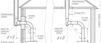
Slopes of pipes of water heating systems
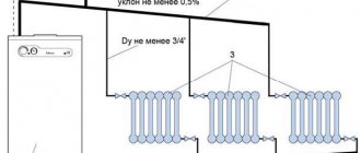
The slopes of the horizontal lines, 2¸5 mm per 1 meter of pipeline, serve to ensure the removal of air from the highest points of the system and emptying of the heating system.
If the supply and return lines are laid together, then for ease of fastening during installation, it is rational to lay them with a slope of 0.002¸0.003 in one direction towards the heating unit.
The supply and return lines to heating devices, with their length up to 500 mm, are laid horizontally; with a slope of 0.005 and 0.01 along the entire length of the line - for a length of more than 500 mm, in the direction of the coolant movement.
Thermal insulation of pipes
When laying in unheated rooms and in places where freezing of the coolant is possible, to reduce heat loss, supply and return lines and sections of risers at the points of connection to the lines are covered with thermal insulation. Thermal insulation can be wrapped, assembled or cast, applied to pipes in the factory. The outside insulation of pipelines is covered with a protective layer: asbestos or aluminum sheet, or synthetic fireproof film. Currently, new thermal insulation materials are being used.
How to calculate the slope of sewer pipes yourself
You can independently find the value of the pipe slope by arranging the sewer system in your house with your own hands. I will tell you how to do this further.
Definition of slope
The main difficulty you will encounter as non-professional builders is that the measure of the slope is not clear. In SNiPs and reference books, which are guidelines for action for any builder, fractions are shown, for example 0.035 or 0.007. Most likely, you are used to using degrees and will not understand what slope of the pipes these numbers indicate.
I hasten to reassure you, everything here is extremely simple: these fractions show the ratio of the height of the depression to the meter length of the pipes. The easiest way to operate the parameter is in centimeters, for example 3.5 cm per 1 m or 0.7 cm per 1 m, as in the examples I gave above.
The length of the network in meters when multiplied by the slope value will give you the total height along the entire length of the branch.
- Let's say the total length of the pipeline is 6 meters and its slope is required to be 0.08.
- Therefore, between the beginning (closest to the drain) and the end (entrance to the riser) of the pipe there should be the following difference: 6∙0.08 = 0.48 m or 48 cm.
How to calculate the fullness of pipes
Sewer pipe fullness.
The main parameter that should be followed when laying a sewer pipe is its fullness. You can determine it according to the formula: u=H/d. In it:
- H is the height of the drain level in the pipe;
- d denotes its diameter.
- when u=0, it means that the pipe is empty;
- when u=1, then it is completely filled;
- The optimal values for fullness (K), at which the drain works most efficiently, is a plug of 0.5-0.6.
This range can be explained by different characteristics of the materials used to make pipes and the level of potential for creating a demarcating layer held near their internal walls.
The filling values I have given will allow waste to flow at a speed of about 0.7 meters per second. It will allow solid fractions to remain suspended and not settle on the walls of the pipes.
Summarizing all of the above, I bring you to the idea that you need to calculate the design characteristics of the pipeline using the formula K≤V√u. In it:
- K - is the optimal degree of fullness (0.5-0.6);
- V - indicates the speed of waste flow;
- √u is the square root of the pipe filling capacity.
How to measure the required angle
You can use the bubble angle to determine the desired angle.
As you already understand, the minimum network slope in apartments depends on the cross-section of the pipes being laid. So, for 50 mm products it should be 3 centimeters per 1 meter of their length, for 85 and 100 mm - 2 centimeters.
- You may be puzzled by the question of how to set the slope of a sewer pipe so that there is no mistake. After all, floors do not always have absolutely correct horizontality. I strongly recommend that you use a laser or bubble level for this.
- I also advise you to tighten the marking cord. You can use it when the branch enters the riser and as a reference vertical.
The angle of entry of the pipe into the riser.
Below I publish for you another table with optimal and minimum slopes of sewer pipes.
| Plumbing fixture | Pipe diameter, in millimeters | Tilts | |
| Optimal | Minimum | ||
| Sink | 40 | 0.035 | 0.025 |
| Toilet | 100 | 0.02 | 0.012 |
| Bath, washbasin, urinal | 40-50 | 0.035 | 0.025 |
| Washing | 40 | 0.035 | 0.025 |
Slope for external sewer pipes
Professional scheme for laying sewer pipes.
In the table below I show the correct slopes for external sewer pipes with a large cross-section relative to the internal part of the system.
| Pipe cross-section, in millimeters | Optimal slope, in meters per 1 m of pipe length | Slope under special conditions, in meters per 1 m of pipe length |
| 150 | 0.008 | 0.007 |
| 200 | 0.007 | 0.005 |
By special conditions, the instructions mean the need to build a system when some reason prevents the optimal slope from being achieved. In other words, this is the minimum acceptable degree of reduction of external sewer pipes.
As I already wrote, there is a maximum value for this parameter. It is equal to 0.15. If the slope is more than 15 cm per meter of pipes, the drainage system will function ineffectively. The network will begin to silt if the liquid is discharged too quickly and will quickly become clogged.
Types of heating systems
The main elements of any heating network are: a heat-generating device, a main pipeline, heat-dissipating, compensation devices and a device that ensures coolant circulation. Heating pipelines can have different configurations and degrees of technical equipment.
Heating systems are classified according to three parameters:
- number of pipe circuits of the main pipeline,
- type of compensation device,
- type of circulation.
One- and two-pipe systems
The heating system can be:
- single-pipe or sequential,
- two-pipe or parallel.
In the first case, the coolant moves along one pipe circuit, alternately passes through all the heat-releasing devices, arriving at each increasingly cooler. The part of the main pipe after the last heat exchanger is called the return pipe or return pipe and serves to drain the cold working medium back to the heat generator.
In a two-pipe system, the energy carrier circulates through two parallel circuits: supply and return. The first circuit supplies hot coolant to each heat-releasing device, and the second circuit collects the cooled working medium from the heat exchangers and takes it to the heating device.
Types of circulation in heating systems
Heating of the premises occurs only if the coolant moves along the circuit. Circulation can be either natural or forced.
In systems with natural circulation, the energy carrier heated by a heating device is accelerated to give it an impulse sufficient to pass through the entire thermal circuit. To do this, immediately after the heat generator, an accelerating manifold is installed - a vertical section of pipe, when descending from which the working medium picks up speed under the influence of gravity.
Types of compensation devices
Depending on the method of compensating for pressure differences of the working medium in the circuit, there are two types of heating systems: open and closed.
In an open system, the pressure is controlled by a compensation tank, partially or completely open. When the pressure in the heating network increases, the excess working medium enters the tank, and when it decreases, it goes back into the pipeline.
Slope
For the proper operation of a heating system with natural circulation, the slope of the pipes is of great importance. According to accepted building codes, this parameter should be within 1% (1 centimeter of excess per meter of pipe length), and the slope is set according to the movement of water. In this case, the rising energy of the coolant will be able to overcome friction, which will facilitate the efficient movement of liquid through the pipes of the heating system.
Note! The height of the ceiling and the level of the finished floor may differ in different rooms of the same country house, therefore, to correctly determine the slope of the pipes, it is necessary to use a building level or hydraulic level. For the normal functioning of the heating system, the slope of the pipes is required.
In one- or two-pipe heating systems, in which the coolant is moved using a circulation pump, it is not necessary to maintain a slope. Such pipelines are installed in a horizontal position or with a minimal slope towards the drain. In such a case, the home owner can quickly drain the water to prevent the system from defrosting in the winter.
Factors affecting heating pipes in the ground
A heating pipe buried in the soil is subject to the same influences as an external pipeline, plus factors caused by deepening:
- internal pressure of the coolant, causing circumferential and elongated tensile stresses in the pipe section;
- temperature of the coolant is a factor, in addition to thermal influence, also causing pipeline stress;
- soil temperature - in winter, taking this into account is very important;
- soil deformations - the pipe is affected by any of its displacements (settlement, shear, etc.);
- pre-bending stress of the pipeline - the ditch profile often follows the local terrain;
- vertical load - the influence of the weight of the ditch backfill layer;
- the resistive action of the soil on the walls and bottom of the pipeline - resistance to vertical load;
- vibration loads - from passing vehicles, excavation work in the neighborhood, etc.;
- moisture – precipitation and groundwater;
- the influence of chemical substances - compounds in the soil and heat carrier;
- biological factor - bacteria, decomposition.
Likewise, laying a pipeline in the soil should be carried out taking into account all the factors listed above and solving the problem of how to make heating pipes in the ground warmer.
Features of polypropylene pipes
To install the pipeline, high-quality and reliable material is required. This could be, for example, stainless or galvanized steel. Over time, polypropylene replaced these types from the construction industry. The main reason was the combination of useful properties at a reasonable price.
Polypropylene is suitable for hot and cold water supply and heating. The material is durable and does not require maintenance, so you can safely wall up water pipes into the wall.
The main thing is that their use does not exceed the temperature limit of 95 ° C, when the material loses its resistance to pressure and deforms. In residential water pipes and heating systems, such pipelines operate at lower operating temperatures, so no problems should arise.
The disadvantage of the material is thermal expansion, which can directly affect the integrity of the wall into which the pipes are walled. The expansion coefficient of polypropylene is quite high. The linear increase can be up to 10 mm per meter of pipe at a temperature of 70 °C; accordingly, the diameter of the pipe also increases slightly.
The higher the temperature, the more the expansion coefficient of the pipe increases. Therefore, the laying of heating networks, their correct installation, and the selection of types of pipes that suit the conditions deserve special attention.
Installation requirements
When laying pipes in the wall, it is recommended to use shock-absorbing materials. For example, energyflex, polyurethane foam. These materials will serve as a gap between the wall and the pipe; accordingly, there will be no pressure on the concrete when the pipe expands.
The fewer connections, the better. Connections are the most vulnerable part of polypropylene systems, least protected from leaks and having low pressure resistance.
Pipes must be selected in accordance with the conditions of further operation.
Based on wall thickness, all PPR pipes are divided into categories from PN10 to PN25.
- PN10 pipes are thin-walled, designed for cold water supply or for heated floors and other low-temperature, low-pressure systems.
- PN16 and PN20 are used for water supply with pressure up to 1.5 MPa and heating systems with pressure not exceeding 0.8 MPa.
- PN25 is reinforced with a layer of fiberglass or aluminum, which increases strength and temperature range. Accordingly, the products can be used in central heating systems at pressures up to 1.5 MPa, and in cold water supply up to 2.5 MPa.
How to organize a connection
The next step in the process is choosing the connection type. The following methods are most effective:
- Lateral one-sided - the inlet is connected to the upper branch pipe, and the outlet is on the same side of the battery, but to the lower branch pipe. The option provides excellent heat dissipation, but is suitable for batteries consisting of 12 sections.
- Bottom - both directions are connected to the lower pipes of the heating device from different sides. The method is ideal for hidden pipe laying.
- Diagonal - the inlet is carried out through the upper pipe, and the outlet is carried out on the other side through the lower pipe. The method is used to connect devices with more than 12 sections.
Connection to polypropylene pipes
To properly install radiators with propylene heating pipes, you will need to acquire a special soldering iron. The connection is implemented using two technologies:
- In the case where the radiator valve is propylene, the connection is made by soldering directly to the liner. Next, you should unscrew the American metal end cap from the tap and screw it into the radiator sleeve. For tightness, FUM tape or linen winding is used. As a result, reassemble the “American” and tighten the union nut with a wrench.
- If the radiator valve is made of metal, then a split-type combined coupling with internal thread is used to connect to the plastic liner. It is similar in principle to the “American” one, but the union nut is adapted for soldering. Through the connecting fitting, the plastic part of the coupling is soldered to the underwater pipe. After this, the coupling must be disassembled, and the metal part with the winding must be screwed onto the valve. Assemble the coupling and tighten the union nut.
Connecting the battery to the metal connection
Many homeowners who want to know how to properly install a heating radiator are worried that when working with metal pipes, they may need a welding machine and related skills in its use. We hasten to reassure you - nothing like that is needed here, everything is done using threaded connections. To do this, a thread is cut on the newly cut section of the eyeliner using a die. The process technology looks like this:
- Cut the supply pipes using a grinder so that the cut line is clearly perpendicular to the center line of the pipe.
- Clean the end of the pipe from corrosion or paint and make a chamfer with a file.
- Apply lubricant to the clamp cutters and pipe section.
- Place the head on the chamfer and center it.
- Using a gas wrench, turn the head clockwise.
- For a high-quality connection, you should get a threaded section equal to the long part of the drive.
As a result, you need to screw a locknut and a coupling onto the finished thread, and aligning the axes of the ball valve and the connection, move the coupling from the connection to the valve body. The process uses rewinding or FUM tape. Next, you should screw the winder onto the thread near the coupling and move the locknut. After final fixation of the stopcock or temperature regulator, it is connected to the radiator liner through the “American” connection.
How and what to seal pipe joints with
Types of seals, sealing methods
To prevent leakage of the pipeline working fluid, it is necessary to properly seal the pipe twists.
When threading steel pipes, the following are used as seals:
- gasket This method of sealing a threaded connection requires relatively thick end pipe cuts. The presence of smooth pipe ends can never ensure tightness. When using a rubber or plastic gasket, this problem is successfully solved. This option is ideal in case of articulation using a union nut;
- winding The materials can be linen strands, polymer threads, FUM tapes in combination with hardening sealants, paints, pastes.
When installing plastic risers, a sealing method is used based on the deformation properties of the material. The essence of this method is that a plastic pipe with an external thread is screwed into a riser with an internal thread. During deformation, plastic contributes to excellent filling of the intermediate space, eliminating the appearance of gaps.
When it comes to pipeline structures with high pressure, cylindrical threaded pipe connections are not entirely appropriate here. In such cases, a conical type connection is used. The principle of connection is that when screwing in, the pipes are tightly pressed until the gap completely disappears.
Materials for sealing joints
To make the joint impenetrable, the following are used as seals:
- flax (tow);
- asbestos;
- FUM tape;
- natural drying oil;
- whitewash;
- minium;
- graphite lubricant, etc.
A reliable sealant when twisting steel pipes onto threads is strands of flax impregnated with red lead or white lead. This connection is easy to install and reliable in terms of sealing. The seal has been used for a very long time and does not lose its popularity today, despite the emergence of artificial analogues.
For those who have little experience in installing fittings and pipes, we suggest that under no circumstances use flax without paint.
At first, the joint will not allow moisture to pass through. But several months will pass, the flax fibers will get wet and begin to decompose. Therefore, the quality of all connections will deteriorate, and in another month or two, water will leak at the junction.
Many people use FUM tape, which is in no way inferior to old traditional materials - tow with paint.
Sometimes there is no tightness at the junction of the risers. To eliminate this defect, you need to replace the sealing material, and clean the threaded area from dirt and sealant residues. After this, rewind the linen thread, FUM tape or other sealant, and assemble the structure.
Pastes and sealants of chemical origin are used as additional sealants, which will help strengthen this section of the pipeline.
Location of radiators in the natural circulation system and their connection
Myth 4th: If the lower radiators are located below the center line of the boiler, then there will be no circulation and the system will not work without a pump.
In fact, for circulation it does not matter at what height the radiators are installed. Sometimes on the lower floor it is simply impossible to place them above the boiler. The incentive for circulation will be the increasing weight of cooling water in the distant riser. It will outweigh the weight of the heated water in the supply manifold. In the same way, cooling in each riser and in the radiators of the upper floors, the coolant under its weight will move through the lower heating devices. Therefore, the statement that there will be no circulation is untenable.
However, there are pitfalls here too.
The fact is that the temperature of the lower radiators, when located at the level of the boiler, will be low. After all, the speed of movement of the coolant depends on the speed of its cooling. At the same height in the system it will have approximately the same temperature. Incorrect installation of radiators for a gravity heating system
That is, the temperature of the radiators located below the boiler will not be higher than that of the “return”. It will be necessary to increase the useful surface area of heating devices by increasing the number of sections or radiators themselves.
Read how to calculate the number of radiator sections per room in a house or apartment.
When developing a heating scheme with natural water circulation, it is recommended to place the boiler as low as possible. If there is a basement or semi-basement, then this is an ideal place for a boiler room. Well, if you still cannot place the boiler at the lowest point of the house, then it is recommended to place the radiators as high as possible.
Correct installation of radiators for a gravity heating system
Features of gravity flow systems
Due to the fact that turbulent flows are formed, it is not possible to carry out accurate calculations of the systems, therefore, when designing them, average values are taken, for this:
• raise the acceleration point as much as possible;
• use wide supply pipes;
Then, from the beginning of the first divergence to each subsequent one, a pipe of a smaller diameter is connected at a step equal to it, which involves inertial flows.
There are also other features of installing gravity systems. Thus, pipes should be laid at an angle of 1-5%, which is affected by the length of the pipeline. If the system has a sufficient difference in heights and temperatures, horizontal wiring can be used
It is important to ensure that there are no areas with a negative angle, since they cannot be reached by moving the coolant due to the formation of air pockets in them
Thus, the operating principle can be based on the open type or be of the membrane (closed) type. If you make a horizontal installation, it is recommended to install Mayevsky taps on each radiator. since with their help it is easier to eliminate air locks in the system.
Watch the video in which a specialist talks about the conditions for using a gravity-fed, pumpless, gravity heating system:
Theoretical horseshoeing - how gravity flow works
The natural circulation of water in heating systems operates due to gravity. How does this happen:
Reference. The dependence of water density on temperature is not linear. The more the liquid heats up, the faster its density decreases, which is clearly visible on the graph.
Example: if you heat 1 m³ of water from 50 to 70 degrees, it will become 10.26 kg lighter (see below for a table of densities at different temperatures). If we continue heating to 90 °C, then the cube of liquid will already lose 12.47 kg, although the temperature delta remains the same - 20 °C. Conclusion: the closer the water is to the boiling point, the more active the circulation occurs.
In a similar way, the coolant circulates by gravity through the home heating network. The water heated by the boiler loses weight and is pushed upward by the cooled coolant returning from the radiators. The flow speed at a temperature difference of 20–25 °C is only 0.1…0.25 m/s versus 0.7…1 m/s in modern pumping systems.
Low speed of fluid movement through pipelines and heating devices causes the following consequences:
As you can see, there are positive and negative aspects in the convection movement of the coolant. The former should be used, the latter should be minimized.
Installing heating radiators correctly: markings
For the correct location of radiators, it is necessary to carry out markings, following all the recommendations set out in the instructions for installing such heating devices. The bottom line is this:
1) first you just need to attach the radiator to the wall, maintaining its horizontal position and the required distances from the floor and window sill;
2) after this, mark its outline with a simple pencil on the wall;
3) then set the battery aside and draw two horizontal lines that will serve as axes for the location of the upper and lower rows of brackets;
5) at the end you should hammer the dowels into them and tighten the brackets.
If the markings are done correctly, the battery will fit on all brackets without any difficulty. Separately, it is worth noting that for heating devices longer than 1 meter, a larger number of fasteners may be required.
Now you can start connecting the battery to the heating system.
Installation recommendations
When arranging a single-pipe heating system, despite its simplicity, it is necessary to carry out all stages of work carefully and competently, taking into account all the nuances and design features.
To ensure everything is done correctly, you should use the following recommendations:
Conclusion
As a result, we can say that a single-pipe heating system, with all its advantages, is completely unsuitable for large and multi-story buildings. In addition, despite its simplicity and low cost, such a system causes many problems and requires a careful approach when arranging.
Testing of the piping system after installation
To start checking the system, you need to acquire a device for deaerating pipes without installing water meters. The process of testing the system is carried out in the following order:
- Fill the pipeline. This should be done from the lowest place in the entire system.
- The area selected for testing should not be more than 100 m.
- Slowly increase the pressure and bring it to the maximum level.
- The check lasts no more than an hour. This time is enough to identify possible leaks.
The installation is complete, and now the pipeline together should form a single heating system.
Other ways to solve the problem
In addition to the use of cast iron batteries, the introduction of a circulation pump into the single-circuit system helps to optimize the situation. After this, the temperature in the heating circuits becomes more uniform, but too long pipelines still lead to its noticeable cooling.
To smooth out this unpleasant phenomenon, two methods are proposed:
- As you move away from the boiler, it is recommended to increase the number of sections on the radiators. In this way, an increase in their heat-releasing area is achieved: thermal energy begins to spread in greater quantities in the rooms, contributing to their uniform heating.
- Before carrying out single-pipe heating, it is necessary to consider the most rational placement of radiators in the rooms. It is better to place devices with the highest power in children's rooms, bedrooms and rooms on the cold north side. Further, the highway leads to the living room and kitchen. At the end of the circuit there are non-residential and utility rooms.
Thanks to these measures, some compensation for the shortcomings of the single-pipe system is achieved. This especially applies to low-rise buildings with an area of up to 150 m². In such cases, single-pipe heating is the most economical option.
Single-pipe horizontal
The simplest version of a single-pipe horizontal heating system with a bottom connection.
When creating a heating system for a private house with your own hands, a single-pipe wiring diagram may turn out to be the most profitable and cheapest. It is equally suitable for both one-story and two-story houses. In the case of a one-story house, it looks very simple - the radiators are connected in series to ensure consistent flow of coolant. After the last radiator, the coolant is sent through a solid return pipe to the boiler.
Advantages and disadvantages of the scheme
First, we will look at the main advantages of the scheme:
- ease of implementation;
- excellent option for small houses;
- saving of materials.
A single-pipe horizontal heating circuit is an excellent option for small spaces with a minimum number of rooms.
The scheme is really very simple and understandable, so even a beginner can handle its implementation. It provides for a serial connection of all installed radiators. This is an ideal heating layout for a small private house. For example, if this is a one-room or two-room house, then “fencing” a more complex two-pipe system does not make much sense.
Looking at the photo of such a circuit, we can note that the return pipe here is solid, it does not pass through the radiators. Therefore, this scheme is more economical in terms of material consumption. If you don’t have extra money, this type of wiring will be the most optimal for you - it will save money and allow you to provide heat to your home.
As for the shortcomings, there are few of them. The main disadvantage is that the last radiator in the house will be colder than the very first one. This is due to the sequential passage of the coolant through the batteries, where it releases the accumulated heat into the atmosphere. Another disadvantage of a single-pipe horizontal circuit is that if one battery fails, the entire system will have to be turned off at once.
Despite certain disadvantages, this heating scheme continues to be used in many small private houses.
Features of installation of a single-pipe horizontal system
When creating water heating for a private house with your own hands, the scheme with single-pipe horizontal wiring will be the easiest to implement. During the installation process, it is necessary to mount the heating radiators, and then connect them with pipe sections. After connecting the very last radiator, it is necessary to turn the system in the opposite direction - it is advisable that the outlet pipe runs along the opposite wall.
A single-pipe horizontal heating circuit can also be used in two-story houses; each floor here is connected in parallel.
The larger your home, the more windows it has and the more radiators it has. Accordingly, heat losses also increase, as a result of which the last rooms become noticeably cooler. You can compensate for the temperature drop by increasing the number of sections on the latest radiators. But it is best to install a system with bypasses or with forced circulation of the coolant - we will talk about this a little later.
A similar heating scheme can be used to heat two-story houses.
To do this, two chains of radiators are created (on the first and second floors), which are connected in parallel to each other. There is only one return pipe in this battery connection diagram; it starts from the last radiator on the first floor. The return pipe coming down from the second floor is also connected there. Date: September 25, 2022
Rules for the selection and installation of pipes
The choice between steel or polypropylene pipes for any circulation is made according to the criterion of the possibility of their use for hot water, as well as from the standpoint of price, ease of installation and service life.
The supply riser is mounted from a metal pipe, since water of the highest temperature passes through it, and in the case of stove heating or a malfunction of the heat exchanger, steam can pass through.
With natural circulation, it is necessary to use a pipe diameter slightly larger than when using a circulation pump. Typically, for heating rooms up to 200 square meters. m, the diameter of the acceleration manifold and the pipe at the return inlet to the heat exchanger is 2 inches.
This is caused by a lower water velocity compared to the forced circulation option, which leads to the following problems:
- reduction in the volume of transferred heat per unit time from the source to the heated room;
- the appearance of blockages or air pockets that a small pressure cannot cope with.
When using natural circulation with a bottom supply circuit, special attention must be paid to the problem of removing air from the system. It cannot be completely removed from the coolant through the expansion tank, because
Boiling water first enters the devices through a line located lower than themselves.
With forced circulation, the water pressure drives air to an air collector installed at the highest point of the system - a device with automatic, manual or semi-automatic control. With the help of Mayevsky taps, heat transfer is mainly adjusted.
In gravitational heating networks with a supply located below the devices, Mayevsky taps are used directly for bleeding air.
All modern heating radiators have devices for releasing air, therefore, to prevent the formation of plugs in the circuit, you can make a slope, driving air to the radiator
Air can also be removed using air vents installed on each riser or on an overhead line laid parallel to the system mains. Due to the impressive number of air exhaust devices, gravity circuits with bottom wiring are used extremely rarely.
With low pressure, a small air lock can completely stop the heating system. Thus, according to SNiP 41-01-2003, it is not allowed to lay heating system pipelines without a slope at a water speed of less than 0.25 m/s.
With natural circulation such speeds are unattainable. Therefore, in addition to increasing the diameter of the pipes, it is necessary to maintain constant slopes to remove air from the heating system. The slope is designed at the rate of 2-3 mm per 1 meter; in apartment networks, the slope reaches 5 mm per linear meter of the horizontal line.
The supply slope is made in the direction of water movement so that the air moves to the expansion tank or air bleed system located at the top point of the circuit. Although it is possible to make a counter-slope, in this case it is necessary to additionally install a valve for air removal.
The slope of the return line is usually made in the direction of movement of the chilled water. Then the lowest point of the circuit will coincide with the entrance of the return pipe to the heat generator.
The most common combination of supply and return pipe slope directions for removing air pockets from a natural circulation water circuit
When installing a heated floor of a small area in a circuit with natural circulation, it is necessary to prevent air from entering the narrow and horizontal pipes of this heating system. It is necessary to install an air removal device in front of the heated floor.
Heating installation without a pump
Now let's figure out how to circulate water without a pump. Since the pressure in the network is equal to atmospheric pressure, the efficiency of the system is significantly reduced if the pipeline slope is incorrectly calculated, a large number of turns of the circuit and violations during installation.
Scheme of a single-pipe heating system for a private house
To install an effective gravity network, adhere to the following rules:
the minimum slope of the return pipes towards the heating boiler should be 0.5%/m.p.; The wiring can be made from pipes with a diameter of at least 5 cm (pay attention to the type of pipeline); take into account the characteristics of the coolant used and the supply diagram.
The easiest way to make the required return slope towards the heating unit is to install it in the basement or basement floor. But if there are no such premises, then the floor in the boiler room on the 1st floor is made slightly lower than the floor level in the house.
Selecting the slope and diameter of pipes
The following pipelines are suitable for the installation of networks with gravity current:
- Steel pipes are durable, affordable and can withstand significant pressure. However, in open networks where air enters, they are susceptible to corrosion.
- Metal-plastic pipelines weigh little and are less susceptible to clogging due to their smooth inner surface. They are resistant to corrosion, and their linear expansion when heated is insignificant.
- Polypropylene pipes are valued for their tightness and strength, durability, ease of installation and resistance to low temperatures. To connect individual sections of the pipeline, you need to buy or rent soldering equipment.
- Copper elements are the most expensive, so they are not used as often. They boast high heat transfer, durability and visual appeal.
To select the correct pipe diameter, you need to carry out thermal calculations. If the cross-section of the main line is too large, then the cost of heating the house will increase significantly. At the same time, the heat transfer of the devices will decrease.
Selection of coolant
Water or antifreeze can be used as a coolant in gravity flow systems. Typically, water is used for these purposes, because antifreeze has a higher density and lower heat transfer, which contributes to increased time and fuel consumption for heating the house.
If in winter the house will not be heated for a long time, then it is better to prefer antifreeze. In this case, while the owners are away, there is no need to drain the water from the system so that it does not freeze. Due to better fluidity, antifreeze does not freeze at sub-zero temperatures.
Upper and lower wiring
The coolant supply to the batteries can be top or bottom:
- Top supply is ideal for houses with gravitational coolant flow. The distribution pipes are laid under the ceiling surface. Due to the upper supply of water from heating devices, it is easy to bleed air using Mayevsky taps. When filling from the top, it is advisable to use single-pipe wiring, because it will be more efficient.
- For a bottom supply device, the pipes must be laid near the floor. Here they are less noticeable, so they do not spoil the interior of the room. But combining bottom feed with single-pipe wiring is not recommended due to its low efficiency. Bottom filling is best done at increased pressure in the circuit.
If the supply method is chosen incorrectly, the efficiency of heating the house will decrease. To solve the problem, you will have to install pumping equipment. The circulation pump will improve the movement of coolant in the network.
Connecting metal heating pipes without welding
The fastest connection method without welding is a compression fitting. However, we will consider other methods: threaded connections and installation of a repair and mounting clip. The latter is used both for joining and eliminating leaks caused by metal cracking.
Thread
It is possible to create a threaded connection only if there is free access to the pipe, i.e. at the initial installation stage. In other cases, thread cutting will be quite problematic or impossible. The procedure itself is carried out according to the following scheme:
- Clean the pipe from paint and rust. If there are metal deposits after previously performed welding, they should be cut off. The surface to be joined must be clean and smooth.
- Using a file, chamfer the end where the cut was made.
- Take a die of a suitable size and screw the handles into it. Lubricate the cutters with grease or lard.
Place the tool on the pipe, making sure that it is positioned strictly perpendicular. Make a half turn of the die clockwise, then a quarter turn counterclockwise. Then repeat the movement until the thread is cut.
Now let's figure out how to cut into a heating pipe without welding. To do this you will need to use a coupling with a nut. It can have three branches to create wiring. When creating a thread, remember that on one pipe it should be 2 times longer. Securing the coupling:
- A nut is screwed onto the longer thread, then a coupling.
- A nut is screwed onto the second pipe.
- The parts are matched together, after which the coupling is twisted off the long thread and partially screwed onto the short one. The element should be approximately in the middle of the cut.
- All that remains is to screw the nuts on both sides, having previously wound a sealing material (fum tape, tow) onto the threads.
Such a connection is considered quite strong and can last for more than one year.
Compression fittings for steel pipes
This type of connection allows heating without welding pipes and cutting threads. At the same time, experts note the high reliability of compression fittings, the leader in production of which is Gebo. This often results in confusion of concepts - many name these connecting devices after a popular manufacturer (a striking analogy is the Xerox brand, which has become a household name for document copying work).
Among the advantages of this connection method are the speed of operation and the absence of the need to use special tools. All you need are two balloon wrenches to hold and tighten the fitting.
The working method is as follows:
- Place the fitting parts onto the pipe in the following sequence: nut, clamping ring, clamping ring, sealing ring.
Put on the coupling, make sure that all elements are positioned correctly and without distortions. Tighten the nut. One turn of thread should remain visible. If after supplying the coolant a small leak appears, the nut can be tightened. Carry out the same actions for the second side of the fitting.
You can learn more about compression fittings by watching the video:
Repair and installation clip
When operating old systems or exceeding pressure, the question often arises of how to seal a heating pipe without welding. For these purposes, a repair and installation clip is used. It can be made in the form of a coupling or tee. The outer part of the part is metal with clamping bolts, inside there is a rubber gasket.
The element is often used for emergency repair of leaks, but can also be used as a permanent option for connecting water supply pipes. Instructions for use:
- Clean the pipe contact areas from paint and other deposits that may affect future tightness.
- Apply a rubber seal to the joint. Make sure that its cut does not hit the junction of the upper and lower parts of the holder.
- Coat the cut with sealant and, if possible, allow some time to dry.
- Install the frame parts and secure with bolts.
These are all options for creating a strong connection between metal pipes without using a welding machine. Now we will describe several methods when working with metal-plastic parts.