An indispensable element of any complex of heating equipment are pressure gauges and a safety valve, which respectively visualize the process of pressure changes in the heating system and protect against exceeding the maximum permissible value.
Pressure gauges are used to control this value and record its deviations from the nominal values. Their decrease by 0.02 MPa (0.2 at) is a signal to search for coolant leaks or check whether the gas (air) pressure in the expansion tank is sufficient. Commissioning of the system is preceded by a mandatory stage of high-pressure hydrotesting, which identifies potential leaks that are subject to early repair.
What pressure does the pressure gauge show?
This physical quantity characterizes the degree of compression of the medium, in our case, the coolant liquid pumped into the heating system. To measure any physical quantity means to compare it with some standard. The process of measuring the pressure of a coolant liquid with any mechanical pressure gauge (vacuum gauge, pressure-vacuum gauge) involves comparing its current value at the point where the device is placed with atmospheric pressure, which plays the role of a measurement standard.
The sensitive elements of pressure gauges (tubular springs, membranes, etc.) are themselves exposed to the atmosphere. The most common spring pressure gauge has a sensing element representing one turn of a tubular spring (see figure below). The upper end of the tube is sealed and connected by a driver 4 with a toothed sector 5, coupled with a gear 3, on the shaft of which arrow 2 is mounted.
Spring pressure gauge device.
The initial position of the spring tube 1, corresponding to the zero of the measurement scale, is determined by the deformation of the spring shape by the pressure of atmospheric air filling the pressure gauge body. The liquid entering tube 1 tends to further deform it, raising the upper sealed end higher by a distance l, proportional to its internal pressure. The shift of the end of the spring tube is converted by the transmission mechanism into a rotation of the arrow.
The angle φ of the latter's deflection is proportional to the difference between the total liquid pressure in the spring tube 1 and the local atmospheric pressure. The pressure measured by such a device is called gauge or gauge pressure. Its reference point is not the absolute zero of the value, equivalent to the absence of air around tube 1 (vacuum), but local atmospheric pressure.
Pressure gauges are known that show the absolute (without subtraction of atmospheric) pressure of the medium. A complex device plus a high price prevent the widespread use of such devices in heating systems.
The pressure values indicated in the passports of any boilers, pumps, shut-off (control) valves, pipelines are precisely manometric (excess). The excess value measured by pressure gauges is used in hydraulic (thermal) calculations of heating systems (equipment).
Pressure gauges in the heating system.
Coolant in static and dynamic states
The coolant of any heating system can be in two states:
- stationary (static), when there is no heating in the gravitational system (no natural circulation) or the circulation pump is turned off in a system with forced circulation;
- mobile (dynamic), caused by the following reasons: natural circulation of the coolant, driven by a pressure gradient due to uneven heating of the working fluid along the contour of the gravitational heating system;
- forced circulation of coolant driven by a circulation pump;
- thermal expansion of the coolant, causing it to displace air/gas from the expansion tanks, occupying the vacated volumes.
The stationary coolant exerts only (hydro)static pressure on the internal surfaces of the system elements, which is studied by hydrostatics. A moving coolant is characterized by (hydro)dynamic pressure, studied by hydrodynamics. It consists of a static component, then a part determined by the thermal expansion of the liquid, and finally a component created by the so-called. high-speed pressure of a moving fluid. Further, when considering a moving heated coolant, we will use the term working (resulting) pressure.
Tank type selection
One of the main elements of a flax tank is the membrane, which largely determines the reliability and durability of the tank as a whole. Therefore, let us dwell on this issue in more detail.
Today, there are several main membrane materials most commonly used by various manufacturers: natural butyl rubber and E DM. The choice of a particular material is based on the tasks that the tank faces when used in a particular system.
Thus, in central heating systems under normal operating conditions, the expansion of the liquid, and therefore the loading of the membrane, occurs slowly, and changes insignificantly throughout the entire operating time of the system. However, the operating temperature can be quite high. Therefore, the membrane for such a system must be made of a temperature-resistant and durable material
In cold water supply systems, the influence of coolant temperature on the membrane is small, since the water temperature in the system usually does not exceed 30 °C. One of the main characteristics of the membrane for this system should be dynamic elasticity, since the system can be turned on several times per hour and quickly loaded.
In most models of Flamco expansion tanks, high-quality natural rubber (butyl rubber) is used as a membrane material, which can withstand temperatures from –10 to +70 ° C (max. percentage of ethylene glycol content 50%), has high resistance to water diffusion and has the greatest elasticity compared with other materials. All modifications of the previously mentioned Flexcon model have such a membrane: C, CE, Pro, M (V 2-12500 l, PN 3/6/10 bar). Their area of application: heating and cooling.
For the membranes of Airfix A and DE expansion tanks (V 2-3000 l, PN 10/16), natural food-grade rubber is used, thanks to which the tank can be used in drinking water supply systems.
And in the new series of Airfix P tanks (V 8-5000 l, PN 10), the membrane is made of EPDM for drinking water, which allows these tanks to be operated at temperatures from –10 to +100 °C.
All Flamco equipment has a certificate of conformity and a Sanitary-Epidemiological Conclusion allowing their use in drinking water supply systems.
There are 3 types of membrane fastening:
1. An irreplaceable membrane that does not stretch, but “rolls” along the walls of the tank, which increases its reliability, and the special design of the clamping ring ensures long service life and prevents a drop in the initial pressure (implemented in Flexcon C and Airfix A models);
2. A replaceable membrane in the shape of a pear, which is attached to the upper flange, almost coinciding in length with the tank, so that when the coolant enters, it rests on the walls of the tank and the load is distributed evenly over the area of the “pear” and there is no tension on its “neck” , which significantly increases the service life of the membrane (implemented in the Flexcon CE model);
3. A replaceable membrane fixed between two flanges at opposite ends of the tank, which, in addition to the advantages listed in the second paragraph, makes the membrane immovable (which is especially important for large volumes), thereby significantly increasing its reliability and service life (models: Flexcon M , on large volumes Flexcon Pro and Airfix P).
Components of working pressure in a heating system
Hydrostatic component
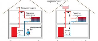
Determined by the design of the system and does not depend on the operation of the circulation pump. There are two known structural types of systems:
- open type;
- (hermetically) closed type.
Two main design types of heating systems.
The coolant of an open system has a free surface inside an expansion tank installed at the top of the system to remove air bubbles. At any point in such a system there is a static pressure equal to the weight of the liquid column above it, plus local atmospheric pressure. The readings of a pressure gauge installed at the lowest point of an open system will be maximum; near the free surface of the liquid they will be almost zero.
It is convenient to measure the (hydro)static component in meters of water column (m. water column), taking into account that a water column 10 m high of any section/shape (regardless of the number/length of horizontal sections) creates a pressure on its base equal to 1 at ≈ 1 bar.
Let's consider some open heating system (the coolant is motionless).
Static pressure at different levels.
Above the upper pressure gauge there is a water column 6 m high -5.5 m = 0.5 m. The readings of the device will be 0.05 at. Two columns of water are simultaneously located above the middle pressure gauge. The first, 6 m – 2 m = 4 m high, is formed by a vertical two-pipe riser with radiators, the second – by the pipeline of the expansion tank and the tank itself, the height of the column is 7 m – 2 m = 5 m. The average pressure gauge will show 0.5 at. Above the lower pressure gauge there is a column of water 7 m –0.7 m = 6.3 m. Its readings will be equal to 0.63 at.
The closed system is equipped with a sealed expansion tank having two chambers (gas, liquid), separated by an elastic membrane. The static pressure of a stationary (steady state) liquid on the membrane must be balanced by the resistance to compression of the gas (compressed air, nitrogen). The initial static pressure of the cold coolant of a closed system, established during initial filling, must satisfy the following two requirements:
- be large enough to prevent “airing” of the system through elements that periodically communicate with the atmosphere: air vents, safety valves, drain valves, etc.;
- Do not exceed the gas pressure inside the membrane tank too much, so that the coolant filling the system does not occupy its entire volume. Otherwise, there will be no room left to accept the excess volume of heated working fluid.
Approximately, the static pressure of the filled cold coolant is taken to be 1.5-1.6 at ≈ 1.5-1.6 bar, which corresponds to the lowest point of the system on the “return” before/after the pump (see figure below). It is to this degree that the nitrogen pumped into “branded” membrane tanks by manufacturers is compressed. The gas setting pressure of the tank should be set (pumping/bleeding gas) below the hydrostatic pressure of the liquid at the installation site by 0.1 at≈0.1 bar, so that some liquid immediately goes inside. This volume will be useful if the unheated coolant undergoes sudden (night) cooling. Compression of the working fluid due to such cooling in the absence of coolant inside the tank will inevitably cause “airing” of the system.
Typical diaphragm tank setting pressure (lower setting).
The remote flags show the values of typical static coolant pressures at characteristic points. The membrane tank can be installed at the top of the system. Typical static coolant pressures corresponding to the top installation of the tank are shown in the following figure.
Setting gas pressure when the membrane tank is installed at the top.
(Hydro)dynamic component
The movement of the coolant is a consequence of the operation of the circulation pump, which creates in any closed loop of the heating system a gradient of (hydro)dynamic pressure that continuously decreases from the outlet to the inlet pipe of the pump. Any pump is characterized by the generated pressure H, m. The physical meaning of pressure is the increment in the energy of the liquid after passing through the working chamber of the pump. In practice, pressure is identified with pressure, interpreting it as the height of the vertical column of water provided by the pump (measured in m.w.c.).
Any (no matter how small) isolated volume of liquid, limited by areas perpendicular to the direction of movement, on the side facing the outlet pipe, is compressed more strongly than on the side of the inlet pipe. The forces created by pressure on opposite (along the contour) sides of the volume turn out to be unbalanced, the fluid begins to move, described by the Bernoulli equation - the basic equation of hydrodynamics.
Although the liquid inside the sensitive elements of pressure gauges is motionless, the dynamic component adds a certain value to the initial static component, which is perceived by the instruments as an increase in the (hydro)static pressure of the coolant. However, this increase is masked by a much larger (1.2 – 2.2 bar/°C) component arising from thermal expansion. The internal volume of the system is characterized by the distribution of the resulting working pressure of the coolant created by the static, dynamic, and thermal components.
Thermal component
The increase in the volume of water when heated by 100 °C is 4%. It seems like a little. However, the lack of free volume to accommodate excess liquid causes (in an absolutely rigid system) a pressure increase of about 3 at/°C. This means that heating ice water to boiling temperature will cause this value to increase by about 300 atm!
Real pipelines are deformed when the coolant is heated. They expand, providing more volume to the heating liquid. Therefore, the actual increase in pressure turns out to be somewhat lower:
- in steel (copper) pipes - approximately 2.2 at/°C;
- in polyethylene (polypropylene), metal-plastic pipes - about 1.2 at/°C.
Even to a non-specialist, it is obvious that it is impossible to allow such an increase caused by the thermal expansion of water. Antifreeze, by the way, has an even higher coefficient of thermal expansion. The excess volume of hot coolant is absorbed into the membrane expansion tank.
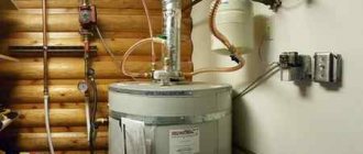
The principle of operation of a membrane tank.
It is important to choose the correct expansion tank capacity. When doing this, specialists operate with rather complex formulas. However, the practice of designing/operating closed heating systems has developed the following rule: the capacity of the expansion tank is equal to 10% of the system capacity.
A correctly selected container/installation location for the expansion tank provides an increase in coolant pressure (at maximum heating) of approximately 1-1.5 atm, which gives a final value of 2.5-3 atm. It is also important to set the system safety valve to a value approximately equal (exceeding a maximum of 10%!) to the maximum permissible for the heating boiler. Usually it is about 3 at.
The distribution of the working pressure of the coolant throughout the system, indicated by pressure gauges, will be similar to the distribution of its hydrostatic component: the maximum values (obviously higher than hydrostatic) will be at the bottom of the heating system, the minimum (also obviously higher than hydrostatic) will be at the top of the system. This circumstance should be taken into account when choosing the location for installing the expansion tank.
Pressure stage
The height to which one must rise or fall for the pressure to change by 1 hPa (hectopascal) is called the “pressure level”. The pressure stage is convenient to use when solving problems that do not require high accuracy, for example, to estimate pressure from a known height difference. Assuming that the atmosphere does not experience significant vertical acceleration (that is, it is in a quasi-static state), from the basic law of statics we obtain that the pressure level h{\displaystyle h} is equal to:
h=−ΔzΔp=1gρ.{\displaystyle h=-\Delta z/\Delta p=1/g\rho .}
At an air temperature of 0 °C and a pressure of 1000 hPa, the pressure level is 8 m/hPa. Therefore, for the pressure to decrease by 1 hPa, you need to rise 8 meters.
With increasing temperature and increasing altitude above sea level, it increases (in particular, by 0.4% for each degree of heating), that is, it is directly proportional to temperature and inversely proportional to pressure. The reciprocal of the pressure level is the vertical pressure gradient, that is, the change in pressure when rising or falling by 100 meters. At a temperature of 0 °C and a pressure of 1000 hPa, it is equal to 12.5 hPa.
Coolant pressure exceeding the limit value
If the operation process is accompanied by frequent “explosions” of the safety valve, you should analyze the possible causes of what is happening:
- reduced capacity of the expansion tank;
- excessive gas/air setting pressure in the tank;
- the installation location is incorrectly selected.
The presence of a tank with a capacity of 10% of the total capacity of the heating system is an almost absolute guarantee of eliminating the first cause. However, 10% is not the minimum possible capacity. A well-designed system can operate normally with a smaller value. However, only a specialist who knows the appropriate calculation methodology can determine the sufficiency of the tank’s capacity.
The second and third reasons are closely interrelated. Let's assume that the air/gas is pumped to 1.5 bar, and the location of the tank is chosen at the top of the system, where the operating pressure, say, is always below 0.5 bar. The gas will always occupy the entire volume of the tank, and the expanding coolant will remain outside. At the bottom of the system, the coolant will put especially strong pressure on the boiler heat exchanger pipes. Regular “explosion” of the safety valve will be ensured!
Adjustment methods
The balancing procedure involves adjusting the shut-off valves. This is done in two ways:
- Adjustment of each valve and temperature measurements after each adjustment of their position;
- Dividing the system into modules and adjusting them separately. In this case, each area of the room receives its share of the total heat emitted by the system.
Before balancing, the heating system is diagnosed by opening all shut-off valves and test running; In this way, it will be determined in which part of the circuit the imbalance occurred.
- Coolant flow and pressure regulators;
- Balancing and bypass valves.
The necessary adjustment components are installed based on the type and complexity of the system.
So, with a single-pipe circuit, ordinary taps will suffice. Balancing the heating system in this case is carried out by simply tightening them until the desired temperature is reached. Two-pipe circuits require balancing valves. They, firstly, provide more precise adjustment, and secondly, they allow you to connect a special device to measure the characteristics of the coolant supply - pressure, flow and temperature. Date: September 25, 2022
A decrease in coolant pressure below normal is a consequence of its leakage
If the value displayed in the absence of circulation has decreased from 0.02 bar, and the gas pressure in the expansion tank is normal, you can begin to look for fluid leaks. It's good if they appear visually. Unnoticeable small leaks are detected by pneumatic testing of the system. Having pumped compressed air inside, wait for the appearance of hissing (whistle) in places of depressurization. They are usually observed at the junctions of pipelines with fittings and heating devices. A good way to prevent coolant leaks is to pressurize the system. This is called high pressure hydrotesting. To fill the system with water, a hand pump is used, which allows you to smoothly raise its value. Having raised it to a certain level, pause for half an hour, monitoring the readings of the pressure gauge. A decrease in the initial value is a clear sign of a leak, which is again looked for visually or audibly by conducting pneumatic tests.
Crimping technology.
Technologies for repairing heating systems are constantly evolving. Relatively recently, a method for eliminating leaks in pipeline systems, including heating systems, has become widespread in Russia, based on adding liquid sealant inside the system (via a pump). Dissolving in the coolant volume, the sealant reacts with air in places of leaks, forming a durable sealing layer, eliminating any leaks in 1-7 days (the period is determined by the size of the defects). The sealant/coolant ratio for the German BCG brand product is 1:100. Therefore, repairing a system with a capacity of 100-200 liters will provide only 1-2 liters of sealant.