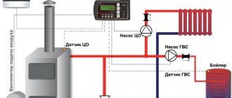
Automation APOK-1 with gas burner device
Ministry of Housing and Communal Services of the Ukrainian SSR Republican Industrial Association "UkrkommunmaSh" Kiev Production Association "Kievkommuntekhnika"
Passport
Installation, adjustment, preventive maintenance and repair of the APOC-1 automation with a gas burner device (hereinafter referred to as the ALOC-1 automation) is permitted only to specialized gas industry enterprises.
PURPOSE OF THE PRODUCT
Automation APOK-1 is designed for automatic protection and regulation of thermal processes of heating water boilers with a power of up to 29 kW in accordance with GOST 20548-81 and GOST 22451-77, operating on low-pressure natural gas.
Automation APOC-1 is produced in the following standard sizes indicated in Table 1.
TECHNICAL SPECIFICATIONS
CONTENTS OF DELIVERY
PREPARING THE PRODUCT FOR OPERATION
1. Ventilate the room in which the heating boiler is installed for 10-15 minutes. Check the operation of the supply and exhaust ventilation by placing a strip of paper near the air ducts.
2. Check whether the gas valves on the downstream side of the boiler and valve 2 (see figure) after the shut-off valve in front of the burner are closed.
3. Check the presence of draft by placing a strip of paper near the ignition hole.
4. Ventilate the firebox and boiler flue for 10 minutes by opening the secondary air damper 6 located on the front sheet under the burner and the igniter window 5. After ventilation, close the secondary air damper.
5. If the boiler was stopped after normal operation, the position of the water temperature regulator indicator 4 should not be changed before lighting.
6. The boiler and heating system are prepared for start-up in accordance with the instructions for the heating boiler.
OPERATING PROCEDURE
a) open the gas valve on the descent to the boiler;
b) open the igniter window 5 and bring in a burning paper bundle;
c) press plate 7 of shut-off valve I;
d) wait until the gas on the igniter ignites and remove the paper bundle;
e) check whether the flame is well washed around the end of the bimetallic plate and close the ignition hole with a damper;
f) keep the shut-off valve plate 7 pressed for 1 minute, then release;
g/ smoothly turn the tap handle with the safety lever 3 installed on it, after the shut-off valve, while the gas should pass to the burner;
h) if the igniter circuit does not warm up the end of the bimetallic plates well or the gas along the entire igniter treadmill ignites, stop ignition and release
plate 7. Repeat ignition, proceeding strictly in the previously specified sequence.
2. Stop the boiler.
a) close the tap on the descent to the boiler;
b) close valve 2 after the shut-off valve;
c) when stopping the boiler for a short time, it is recommended to turn off only the burner by turning the handle of tap 2, while only the igniter lights up, which facilitates further ignition;
d) if the main parameters deviate beyond the established limits, the gas to the burner and igniter is automatically cut off. In this case, you must immediately close the gas taps in the order specified in points “a” and “b”;
To identify and eliminate automation malfunctions or other problems, it is necessary to call a fitter at a specialized gas industry enterprise.
MAINTENANCE
1. The temperature that the water temperature regulator 4 must maintain is set by turning the pointer to the required position. To increase the temperature maintained by the regulator, turn the pointer towards the “hot” side, and to lower it - towards the “cold” side. A thermometer must be installed on the boiler outlet manifold, which is used to control and set the temperature of the heated water entering the heating system.
2. It is prohibited to regulate the gas flow to the burner using taps located in front of the shut-off valve, including the tap on the lower side to the boiler.
3. The regulation principle carried out by the APOK-1 automation ensures a stable air temperature in the room with small external changes in meteorological conditions without outside intervention. If there are significant changes in the heat loss of the building, it is necessary to call a specialized gas service technician to re-adjust the automation.
4. Automation should be protected from mechanical damage; no objects should be placed on the automation devices.
5. It is necessary to periodically clean the igniter and burner treadmill holes to prevent clogging or carbonization of these holes.
SAFETY
1. If the smell of gas is detected, it is prohibited to start ignition.
2. While observing the combustion, do not put your face close to the ignition hole.
3. Operating a boiler with a faulty automatic safety unit is not allowed.
CERTIFICATE OF ACCEPTANCE
The APOC-1 automation system was manufactured in accordance with TU 204 of the Ukrainian SSR 124-82, tested, accepted by the quality control department and declared fit for use.
QC release date
TRANSPORTATION AND STORAGE
APOK-1 automation is transported to the customer by any type of transport.
The placement of APOC-1 automation assembly units and their fastening during transportation should ensure their safety.
APOK-1 automation systems should be stored at temperatures from +5 °C to +35 °C and relative air humidity in the range of 60-80%.
After transportation in packaging at sub-zero temperatures, the APOK-1 automation must be kept at storage temperature for 24 hours before installation on the boiler.
WARRANTY
The manufacturer guarantees compliance of the APOK-1 automation with the requirements of the technical specifications TU 204 of the Ukrainian SSR 128-82, subject to the conditions of operation, storage, transportation and installation.
The warranty period is 12 months from the date of sale through a retail network, and when supplied for off-market consumption - from the date of receipt by the consumer.
The warranty period for the operation of the APOK-1 automation system, which has been duly assigned the State Quality Mark, is 18 months from the date of sale through a retail distribution network, and for supplies for off-market consumption - from the date of receipt by the consumer.
If factory defects in the automation are detected during the warranty period, the owner should call a representative of a specialized gas enterprise to draw up a report indicating the malfunction and send: the faulty unit, report and passport to the manufacturer at the address: 252116, Kiev-116, st. .Sholudenko, 30 KPO "Kievkommuntekhnika".
For which boilers is it applicable?
The shut-off valve for the gas burner device APOC-1 is an original spare part and is actively used for replacement on all boilers with this type of automation (KChM, KST and others).
A copper glass with a 1/2″ external thread is used for immersing a heat-sensitive cylinder or thermometer into the boiler. Length 120 mm. Sleeve diameter 16 mm.
A copper glass with a 3/8″ external thread is used for immersing a heat-sensitive cylinder or thermometer into the boiler. Length 120 mm. Sleeve diameter 12 mm.
The thermostat for a gas boiler is designed to maintain the set (required) temperature.
The temperature regulator is used for automatic protection and regulation of thermal processes of heating water heating boilers, which have a thermal power in the range from 12 to 25 kW, operating on low-pressure natural gas.
The temperature regulator for the boiler is used in boilers of the following types: KChM-1, KSG-10, KSTG-16, KSTG-20, AOGV-80, etc.
Gas filter , aluminum, with connection with internal threads 1/2″, designed for cleaning dry gases (natural gas, liquefied gas) from mechanical impurities.
Gas filters contain a serviceable cartridge (for inspecting the condition of the filter and cleaning it) with a replaceable filter element made of washable synthetic material.
What is the need for and how does automation work on old-style gas boilers?
The newest models of gas boilers are characterized by high power and heating speed. However, their prices are steep, to put it mildly. You can try to use a more economical option and install new automation on the old boiler or fix the old one. The operating principle and automatic design of old-style gas heating boilers will be explained in this article.
- 1 Why do you need gas automation?
- 2 The principle of operation of automation on old-style gas boilers
- 3 Basic elements of automation
- 4 Flame and draft sensors
- 5 The most common automation malfunctions and methods for eliminating them
Why do you need gas automation?
Old-style boilers were manufactured in accordance with the gas parameters and heating system features that were in use several decades ago. These are, for example, models KChM, AOGV. At the same time, their durability allows them to be used for many years to come. But the problem with automation is that quite often it breaks down. In such a situation, there are three options:
- diagnose existing automation and replace the necessary parts;
- equip a reliable and high-quality unit with a modern automatic system;
- buy a new boiler.
The difference, of course, is in the price of the issue, the effort and time of the owner.
Let's consider the cheapest option - troubleshooting gas automation on an old boiler. However, first, let’s figure out why an automatic system is provided in the coolant in general.
Gas automation allows you to regulate and maintain the required level of coolant temperature, and also serves to automatically stop the gas supply in an emergency situation. Installing automation on an old gas boiler will allow you to be sure that if the burner flame goes out, then after a short time the system will work to stop the gas supply without your participation.
If you want to change the automation, keep in mind that domestic manufacturers produce models that are suitable for almost any old coolant. Imported automation cannot be installed on everything. In addition, when installing foreign automation on old-style gas boilers, not all of its functions may work - the design features of the boiler will not allow it.
Manufacturers
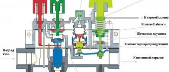
Automation for gas heating boilers Eurosit (Italy). In first place in the popularity rating in the Russian Federation. Simple device, reliability, non-failure operation. All devices are assembled in a monoblock.
Gas pipes, a capillary tube from a thermocouple and a draft sensor, an igniter gas pipeline, and a piezoelectric element cable are connected to the body. The housing itself contains a pressure regulator, an electromagnetic shut-off valve, and a spring valve.
The purpose of the solenoid valve is to shut off the fuel supply. The user presses the adjusting washer, the valve opens, gas flows to the igniter.
While continuing to hold the puck, the user presses the piezoelectric ignition button. The igniter heats the temperature-sensitive element, which then holds the valve open.
After heating, the washer must be turned to the desired division on the graduated scale and thereby open the fuel supply.
Automation for gas heating boilers Fakel-2. Designed for boilers with a power of up to 50 kilowatts.
Functional:
- gas supply to the burner;
- maintaining the temperature specified by the settings;
- automatic shutdown if the pilot light goes out or there is no draft in the chimney;
- automatic shutdown of the supply at low pressure in the line;
- manual shutdown of supply, incl. when the igniter is burning;
- manual adjustment of burner power.
Automation for gas heating boilers Arbat. Non-volatile system, multiblock for boilers up to 50 kilowatts. The functionality is standard.
Video about connecting a room thermostat or boiler programmer.
The latest gas boilers are characterized by very high efficiency and power density. But their cost somewhat limits their scope of application, and it is irrational to throw away old boilers. Modern gas automation for an old boiler significantly increases its efficiency, safety level and profitability.
This is achieved through the use of micro-flare burners, precise thermostats, circulation pumps and other devices that increase the efficiency of heat transfer from burned fuel and reduce heat loss during coolant circulation. Modernizing an old boiler very often involves a significant amount of work to change the configuration of the entire heating system.
Old-style boilers, for example KChM, KST, KSTG, AOGV, were designed for gas parameters and the features of heating systems, the standards of which were changed decades ago. But the durability and quality of workmanship allow these boilers to be used for many more years. The technical characteristics of most old domestically produced boilers make it possible to select an automation that most advantageously uses the design features of the firebox and heat exchanger of a certain model.
The principle of operation of automation on old-style gas boilers
Frequent problems when heating a room with gas boilers are flame attenuation in the burner and gas pollution in the room. This happens for several reasons:
- insufficient draft in the chimney;
- too high or too low pressure in the pipeline through which gas is supplied;
- the flame on the igniter goes out;
- leakage of the pulse system.
When these situations arise, the automation is triggered to stop the gas supply and prevent the room from becoming gas-filled. Therefore, installing high-quality automation on an old gas boiler is basic safety rules when using it to heat a room and heat water.
All automation of any brand and any manufacturer has one operating principle and basic elements. Only their designs will differ. Old automatic machines “Plamya”, “Arbat”, SABC, AGUK and others work according to the following principle. When the coolant cools below the temperature set by the user, the gas supply sensor is activated. The burner starts heating the water. After the sensor reaches the user-specified temperature, the gas sensor automatically turns off.
On a note! When using modern automation, it is possible to save heat up to 30%. Old-style automation is non-volatile and does not require electricity. Its adjustment, connection and disconnection are carried out by a person. Commands are transmitted using electromagnetic pulses.
The video explains how the automation of gas boilers AOGV and KSTG works.
Basic elements of automation
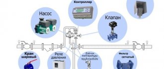
The main elements of automation for a gas boiler are:
- thermostat;
- shut-off valve;
- traction sensor;
- flame sensor;
- igniter tube;
- igniter;
- burners.
Let's try to clearly explain how automation for a gas boiler works, breaking it down into its main elements and talking about their functions.
The gas passes through a gas purification filter. Next it goes to the solenoid valve, which regulates the fuel supply to the burner. Temperature and draft sensors are located next to the valve, monitoring the indicators and signaling if they exceed acceptable standards. Also, the automation kit for gas boilers includes a thermostat with a bellows and a rod, designed to set the desired temperature. A special button is used to adjust the indicators. When the water is heated to the temperature set by the user, the thermostat is activated, the gas supply to the burner is stopped, while the igniter continues to operate. When the water cools by 10-15 degrees, the gas supply is resumed. The burner lights up from the igniter. The automation is started manually.
Description
The shut-off valve in the APOK-1 automatic system is used to shut off the gas supply in critical (emergency) situations. This reducer also regulates the gas supply.
The shut-off valve is an original spare part for the APOC-1 gas burner device and is suitable for all boilers where this automation is installed (KChM, KST and others).
We also offer other components for gas automation APOK-1 : thermocouples, igniters, flame sensors, temperature regulators, etc.
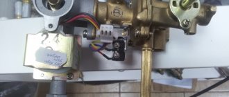
Flame and draft sensors
Flame and draft sensors work on this principle. The draft sensor reacts to deteriorating smoke draft and transmits an impulse to the control system. It is located in the smoke hood. Equipped with a plate made of an alloy of two metals: iron and nickel. When draft deteriorates, flue gases accumulate and heat the plate. It becomes deformed, the contacts open, and the flow of fuel into the combustion chamber stops. When the temperature decreases, the plate returns to its normal state.
The temperature sensor works on the same principle. When the water in the boiler heats above the set temperature, the lever mechanism is activated and the temperature regulator valve closes. The gas supply stops and the burners go out.
When the water cools, the sensor bellows contracts, the lever mechanism is activated, the temperature regulator valve opens, gas begins to flow, and the burners light up.
Non-volatile automation
Mechanical automation for gas heating boilers does not require electricity. The design of the devices is simpler, the price is lower, and the operation of the system is not affected by network outages.
An exception is heating with forced circulation: the pump needs electricity. No control devices. There is no need to buy an uninterruptible power supply, a voltage stabilizer, or spend additional money on electricity.
Control is carried out manually by the user. This is more complicated: you can’t just connect the boiler and forget about it. But many owners prefer this option.
For reasons of low cost of equipment, energy savings, and also due to ease of maintenance: electronic automation for household gas heating boilers is difficult to repair on your own in the event of a breakdown. However, in terms of fuel economy, manual control is inferior to electronic control.
The purpose of mechanical automation is the same as that of electronic automation: ensuring safety and controlling settings. The working element of the device is a heat-sensitive substance. Typically this is a thermocouple with an iron-nickel alloy (Invar) core placed in a heat exchanger.
The device functions like this:
- The user sets the temperature settings using the controller.
- When heated, the core lengthens and puts pressure on the gas supply valve. The valve closes.
- As the temperature decreases, the core shortens and the valve opens.
The draft sensor in boilers with atmospheric burners, located in the smoke hood, works in the same way.
Here the working element is a bimetal plate, which deforms when heated to 70 degrees and opens the contact, and when the flame decreases it takes on its previous shape.
The most common automation malfunctions and methods for eliminating them
Before setting up the automation on the boiler, it is necessary to diagnose it. As a rule, serious malfunctions occur that will require specialist intervention. The adjustment can also be entrusted to a gas technician. Or you can do it yourself by reading the instruction manual.
Attention! Before each seasonal operation, it is necessary to check the operation of the safety sensors.
Most often, the filter becomes clogged, problems arise with the valves, sensors burn out due to power surges, and a gas leak is detected. Proper cleaning of the filter should be done by a professional. You can try to replace electronic elements yourself by carefully studying the operating instructions for your boiler.
In order to replace the temperature sensor, you need to turn off the gas boiler and cool the water to a temperature of 40 degrees. Shut off the flow of coolant, remove the control knob by unscrewing the screw. Next, remove the PTV adjustment screw. Remove the sensor bellows with the support washer. Unscrew the union nut of the sensor thermal bulb. Install the thermal bulb of a working sensor into the boiler jacket and screw it tightly. Install the sensor bellows into the pipe socket, install the support washer on the bellows, install the PTB adjustment screw and adjust the temperature.
If problems arise with igniting the igniter, then one of the possible causes is a malfunction of the draft sensor. In this case, it must be dismantled, diagnosed, checked contacts, cleaned, and, if necessary, replaced with a new one.
Also, common reasons why the pilot light does not light may be:
- gas valve malfunction;
- clogging of the hole in the igniter nozzle (it can be cleaned with wire);
- strong air draft;
- low gas inlet pressure.
When the gas supply is turned off, it is necessary to check the chimney (it may be clogged), the electromagnet, and the gas pressure at the inlet to the gas boiler.
Attention! To diagnose and repair the gas boiler automation, you must invite a specialist. Inept actions can aggravate the problem and lead to undesirable consequences.
For the automation of AGUK, AGU-T-M, AGU-P systems, the most common problem is the burnout of the bimetallic plate, which is used as a sensitive element.
In Arbat and Orion, you can only replace the thermocouple and draft sensor, as well as the solenoid valve (rarely). The automation unit is practically beyond repair. In Arbat, the system shutdown button often breaks down.
Typical problems for SABC automation are damage to the main valve membranes and drying out of the thermostat stuffing box, resulting in gas leakage. Impulse tubes, bimetallic plates, and ball valves are subject to control.
In conclusion, I would like to emphasize once again that automation is designed to maintain the operation of heating equipment in a safe mode. Therefore, it is simply necessary for owners of gas boilers.
This video shows how to troubleshoot an automatic boiler AOGV, step-by-step assembly process and testing the result.
Flame sensor - draft sensor - bimital plate APOC-1
APOC-1 Mechanical thrust-flame sensor. (bimital plate)
-
- Remove this product from my favorites list
- Add product to Favorites
- Seal
- More details
- Reviews
Flame sensor - draft sensor - bimital plate APOC-1
For safe and automatic operation of the gas heating boiler, a protection and automation system is provided. It is responsible for maintaining the specified temperature conditions, as well as for the safe operation of the unit. One of the main elements of unit protection is the gas boiler draft sensor.
1 Purpose of the draft sensor
2 Design and principle of operation of the draft sensor
3 Reasons why the traction sensor is triggered
4 Popular models of draft sensors for gas boilers
Purpose of a draft sensor A draft sensor or thermostat is a device for determining the intensity of draft in the chimney of a gas boiler. Its main function is to provide a timely signal about an unacceptable amount of draft in the boiler.
A malfunction of the traction sensor can result in an emergency. After all, sufficient draft is necessary not only for drawing out smoke, but also for efficient combustion of gas. If there is no draft, then the combustion will be unstable, and this can affect the integrity of the entire unit. Poor draft can cause a gas boiler to go out.
Design and operating principle of a draft sensor There are 2 types of gas boilers: with natural and forced draft. The traction sensors in them are also different. Boilers with natural draft use an open combustion chamber, and draft is created by selecting the correct dimensions of the chimney (height and cross-section). Such units use a traction sensor based on a bimetallic element. This is a plate of certain dimensions with a contact attached to it. It is installed in the gas path of the unit and reacts to temperature changes. If the draft in the boiler is good, the temperature will be low. As the thrust intensity drops, the temperature will begin to rise and cause the metal of the plate to expand. Its material is selected in such a way that when a critical temperature is reached, the contact is disconnected and the gas valve closes. After the temperature drops, the valve closes again. The critical temperature is set by the gas boiler manufacturer and can be located in the range of 75-950C.
On a note. “Backdraft” - this phenomenon occurs in the absence of vacuum in the combustion chamber. It can only be observed in boilers with natural draft and an open combustion chamber. During normal operation of the boiler, air is constantly sucked into the combustion chamber, and if the draft disappears, the smoke will flow in the opposite direction, not from the room, but into it. This is “reverse thrust”.
Boilers with forced draft have a closed combustion chamber, and the draft is created by the operation of a fan. Therefore, in such boilers a draft sensor in the form of a pneumatic relay is used. It provides control over the operation of the fan and the intensity of removal of combustion products. The sensor is a membrane that bends under the influence of the flue gas flow created by the smoke exhauster. If the flow weakens, then the membrane voltage drops, at a certain moment the contacts open and the gas valve closes.
Reasons for the draft sensor to be triggered Various factors can cause the draft sensor to trigger: Clogging of the chimney. Incorrect installation of the chimney for a gas boiler, or an error in calculating its dimensions. The gas boiler was installed incorrectly. Fan stop (in forced draft boilers).
Attention! If the traction sensor triggered, then there were good reasons for this; you should look into them carefully. But it is strictly forbidden to forcibly close the contacts of the draft sensor to resume boiler operation. It is also not permissible to operate the boiler without a working draft sensor.
A temperature sensor for boilers with natural draft and a pneumatic sensor for boilers with forced draft are reliable elements of protection for gas heating boilers. For additional protection, you can install an external air gas analyzer to detect gas contamination. This will ensure complete control of the boiler operation, even if one of the sensors malfunctions.
Types of valves
The gas valve is responsible for regulating the gas flow, its distribution and shutting off. The valve has a hole for the passage of gas (the so-called seat), closed by a piston or disk.
Depending on the number of inputs and operating positions, there are one-way, two-way and three-way valves, as well as modulating ones:
- a one-way valve is either open or closed;
- two-way is equipped with one input and two outputs. The start is smoother due to opening through an intermediate position;
- three-way valves are installed on boilers with two-stage power;
- With the help of modulating valves the power can be adjusted smoothly.
Accordingly, gas burners (types of gas burners for heating boilers) with automation for heating boilers come with single-stage, two-stage or modulated power control.
Block - security
The safety unit consists of a shut-off valve, a draft sensor, a flame sensor with an igniter and impulse tubes. As can be seen from the diagram shown in Fig. 17, the gas enters the shut-off valve into the space above the small membrane and does not pass further. When igniting, the plate of the shut-off valve is pressed, its rod rises, the gas is directed to the igniter, where it is ignited with a match or torch, through the throttle it is supplied under the large membrane and then along the impulse tube to the emergency mode sensors - the draft sensor and the flame sensor. No gas is supplied to the burner because the gas valve is closed. [2]
The boiler safety block with its valve cuts off the gas supply to the burners according to pulses received from the vacuum control sensors 13, the water temperature in the boiler 17, the presence of flame 16 - 18, and thanks to the original device of the vacuum sampling chamber, all of the listed pulses activate the safety block valve through its vacuum control device. [3]
A safety block has been created for high-force crank presses, which is a stand adjustable by means of a screw, which is placed on the presses in the socket of the frame. [4]
Each security unit is equipped with a switch, the contacts of which are connected in series to the alarm line connecting the boiler room to the control room. When any of the shut-off valves of the safety unit are triggered, the contacts of its switch open, which causes the alarm line to de-energize. At the same time, a red light on the control center console lights up and a sound signal sounds. The alarm line is supplied with 24 V DC through the alarm unit. [5]
A number of presses are equipped with safety blocks that ensure safety when finishing and repairing the die without removing it from the press. The safety block (Fig. 85) consists of a housing 5 with a handle and a screw 6 screwed into it, the rotation of which adjusts the overall height of the block. The block is installed on bracket 2, rigidly fixed to the press frame. In the top 7 and bottom 8 plates of the die, areas of 150X150 mm in size or 150 mm in diameter must be provided for installing blocks when finishing or repairing dies directly on the press. To remove the block from the bracket, it is necessary to disconnect the connector by rotating the nut of the plug connector 1. In this case, the control circuits of the presses are broken. The press can be put into operation only after installing the blocks in place and connecting the connectors. [6]
Each boiler has a safety block 8, which is a shut-off valve on which are mounted: a gas pressure control device, a vacuum control device, a signaling device and a fuse. [7]
The safety of the installation is ensured by a boiler safety unit and a gas pressure monitoring device or a general boiler safety unit. [8]
The pressure pulse from the gas pipeline is supplied to safety block 6 through a tube and through throttle Dr. Tube a is connected to tube b, which in turn is connected to the vacuum pulse sampling chamber 11 of each boiler. During normal operation of the boilers, tubes a and b are sealed and block 6 records the pressure in the gas pipeline. In the event of sharp pulsations (pops and explosions) in the boiler furnace, a valve connecting the tube b to the atmosphere is activated. In this case, the pressure in tube a drops, which leads to the gas supply to the burners being cut off. [9]
The pressure pulse from the gas pipeline is supplied to the safety unit through a tube (o) through a throttle. Following the continuation of this tube (b), the pulse is supplied to the valve of the KOR vacuum extraction chamber for each boiler. During normal operation of the boilers, tube a is sealed and the safety unit records the pressure in the gas pipeline. If sudden pulsations (popping) occur in the boiler furnace, the KOR valve is activated. In this case, the pressure in tube a drops, which leads to the gas supply to the burners being cut off. The boiler is fed by a pump connected to a feed valve. [10]
The pressure pulse from the gas pipeline is supplied to the safety unit through a tube and through a throttle. Along the continuation of this tube b, the pulse arrives at valve 16 of the vacuum sampling chamber / COP for each boiler. During normal operation of the boilers, tube a is sealed and the safety unit records the pressure in the gas pipeline. In this case, the pressure in tube a drops, which leads to the gas supply to the burners being cut off. [eleven]
The pressure pulse from the gas pipeline to the safety unit is supplied through tube a through the throttle, then through tube b the pulse is supplied to the valve of the KOR vacuum sampling chamber for each boiler. [12]
The automation system performs the functions of protection (safety unit) and regulation. The safety unit is designed to ensure proper ignition of the boiler and shut off the gas supply to the burners in the absence of draft and the flame goes out, or the impulse lines are broken. Regulation is carried out based on the water temperature at the boiler outlet. [13]
If there is a violation of any of the monitored parameters of the boiler safety unit, then the contact of the corresponding relay de-energizes the 2PA boiler emergency relay, breaking the common power circuit of the windings of all three gas solenoid valves. The control and working solenoid valves are closed, and the section of the gas pipeline between them is switched by the ignition-purge valve to the safety plug. [14]
To activate the automatic boiler safety system, turn the safety unit handle counterclockwise until it stops. After 5 - 10 seconds, the handle is returned to its original position. [15]
Portal about construction
Statistical studies show that at least 50% of heating equipment runs on natural gas.
This popularity is due to objective reasons - convenience and ease of use and the relatively low cost of the energy carrier (natural gas).
Talking about an automatic gas boiler in this article, we will immediately make a reservation that any modern gas boiler is automatic, that is, it does not require daily cleaning and loading of fuel like boilers running on solid fuel or periodic refueling like boilers running on liquid fuel.
The difference is that “simple” boilers are equipped with a standard set of automation and protection, while “complex” boilers are equipped with additional options that improve their maintenance and configuration.
Gas boiler safety automation
In general, the automation of a gas boiler consists of the following components and parts:
- Thermal balloon. It is a small container filled with a special gas. When heated or cooled, the gas increases (decreases) in volume and this activates the “accordion” of the bellows, which presses the gas supply “button”. Installed on the top of the heat exchanger or coolant reservoir. Depending on the temperature, it turns on or off the gas supply to the gas burner.
- Thermocouple. It is a bimetallic plate located in a “wick” gas burner. The thermocouple is electrically connected to the main automation unit and is designed to open or close the gas supply depending on the presence or absence of a flame. It should be noted that the potential difference in the thermocouple (signal to open the gas supply) occurs after it has completely warmed up for 20-30 seconds.
- Main automation unit. It consists of a manual coolant temperature regulator, a main gas supply button and an emergency button. When you press and hold the main button, the gas supply to the “wick” burner opens, and when you press the emergency button, the gas supply immediately stops.
Automatic gas heating boilers. Automation operating principle
The operating principle of conventional automation is very simple and if all parts and components are in good working order, the automation does not require daily or even monthly attention. Starting the boiler and its subsequent operation is carried out as follows:
- The ball valve located on the main supply pipeline opens.
- The temperature regulator is set to min. Usually this is the number “0” or “1”.
With one hand, press and hold the main feed button located on the main automation unit. If this is the first start of the boiler (after a summer or other long-term stop), before starting the ignition process, you must hold the button for 2-3 minutes.
This is necessary so that the pipeline from the ball valve to the burner is filled with gas.
Readiness control - slight smell of gas. By holding the button, the “wick” burner is ignited (with a match or piezo ignition).
After making sure that the gas is burning, to warm up the thermocouple, we continue to hold the button for another 20-30 seconds. Better 1 minute. Let's release the button. If everything is in order, the thermocouple gives a signal to the main unit, the main gas supply to the burner(s) opens, the boiler starts operating in automatic mode.
At the same time, automatic gas burners for boilers, as a rule, consist of three burners - a “wick” burner, which burns constantly as long as there is a gas supply, the main one, which heats the coolant to the set temperature, and an “economical” burner, which maintains combustion and turns off when the main burner is turned on.
Depending on what temperature of the coolant the temperature regulator is set to – numbers from “0” to “6”, the coolant is heated to a temperature of 20 to 70 degrees Celsius.
After heating the coolant to a certain temperature, the main burner turns off, the economical one turns on, the coolant cools down to the temperature of the differential setting of the temperature controller, the economical burner turns off, the main burner turns on - the cycle repeats.
We looked at the general case - the simplest automation system for a gas boiler. It should be noted that there are more complex automatic systems, the design of which includes all of the above and additionally:
- Thermostat to turn off the boiler in case of emergency increase in water pressure.
- Traction control sensor.
- Remote ambient temperature sensors.
- Sensors for monitoring external air temperature.
- Boiler blocking in case of emergency decrease in gas pressure.
- Power control unit.
- And other options and “excesses”.
Electronic automation
Volatile automation requires electricity. Dependency on the network is compensated by ease of use and resource savings. The design is based on a system of solenoid valves controlled by a microprocessor unit.
The settings are carried out using buttons on the control panel. All information is displayed on the display. The functionality of the system is to control the fuel supply, flame power and other boiler operating parameters (selection of economical gas heating boilers for a private home).
The function of the thermostat (thermostat) is to control the temperature in the room. When it drops below the setting value, a command is sent from the thermostat to the working unit of the boiler, and the boiler turns on automatically (about heating schemes for a private house with a gas boiler).
After reaching the set value, the supply valve closes and the boiler stops.
Programmer. It has the same purpose as a thermostat, but it is possible to program daily settings for heating and domestic hot water. Connection to the boiler - wired or wireless (using a radio signal).
1 — gas pressure after GRU – ADN-10.1; 2—tightness control—ADN-10.1; 3 — gas pressure in front of the burner — ADN-10.1; 4 — air pressure in front of the burner — ADN-10.1; 5 - vacuum in the furnace for protection and regulation - ADR-0.25.1; 6 - pressure in the furnace - ADN-10.1; 7 – vacuum in the chimney – ADR-0.25.1; 8 — water temperature; 9 — ADP flame sensor-relay; 10 — boiler controller AGAVA 6432.1.
In addition to daily allowances, there are also weekly programmers; they have more capabilities and a significant range of action, at least 30 meters.
Additionally, the electronic system can monitor the pressure in the gas pipeline, carry out self-diagnosis of the boiler, prevent freezing, control the pump, etc.
Single-circuit gas heating boilers with automation can be equipped with a remote control function: for example, you can set settings from work or from the road via the Internet or a cellular provider.