Mechanical models
The valve and thermal head are the main elements, without which it is impossible to imagine almost any thermostat. In this case, the latter performs the function of a sensitive element. These parts do not require external energy in order to function properly.
In turn, the thermal head also has several components. This is a regulator and drive, a liquid element, sometimes elastic or gas parts are found as an alternative.
Internal organization
When choosing a temperature controller, it is necessary to take into account all factors that may affect the operation of the device in the future. Its main parts are as follows:
- adjustable scale;
- ring that fixes the set temperature;
- mechanism of compensatory action;
- union nut;
- stock;
- spool;
- detachable connection;
- sensing element;
- thermostatic element;
- thermostatic valve.
The simplest way to adjust the temperature of a heated floor
My videos often talk about how to connect a heated floor pump to a surface-mounted thermostat. In this case, the thermostat is mounted on the return manifold of the heated floor distributor. I also very often respond in letters about how to do this.
But there are no fewer questions regarding this moment. Either from ignorance of the school physics curriculum, or from laziness, or for some unknown reason. Well, as they say: If only there was a buyer, there would be a merchant!
Anyone who has been following my work for a long time knows that I am not a stranger to any simple methods of adjusting the floor. Give me mixing modules, wireless room thermostats and servos. But it so happened that my colleagues began to use a simple scheme for adjusting the heated floor. At the same time, the system turned out to be simple, inexpensive and terribly reliable that even my desire for perfectionism did not bypass this creation.
That’s why I decided to cover this wonderful topic in detail, so that there would be fewer problems with adjusting the heated floor. Therefore, read carefully and apply diligently.
The essence of the simplified adjustment of a heated floor is to install a surface-mounted underfloor heating distributor on the return manifold or with a remote thermostat sensor , which controls turning the circulation pump on and off. Thus, hot coolant with a temperature of 65-85 degrees enters the system.
I can already hear the screams of the floor installers, who unanimously shout that this is an unacceptable temperature for a water-heated floor system. But as they say, there are exceptions to every rule. So it is in our case. Before solving the plowshare problem, you can listen and try to find a rational link in the described method.
Let's go. In order to implement this scheme for adjusting the temperature of a warm water floor, several conditions must be met.
First condition: The installed heated floor pipe must withstand a temperature of at least 90 degrees.
Second condition: You must immediately decide where the pump will be. In the boiler room or on the floor heating distributor itself. This is necessary in order to lay the power cable .
And the third condition: This is an understanding of the essence of this method of adjustment. Or rather, this is the first condition. But nothing. We'll figure it out along the way .
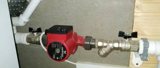
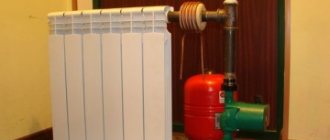
Now let’s imagine that all these conditions are met. Therefore, we begin installation. Installing the relay itself is not difficult. We mount it on the distributor return using a spring. The spring comes complete with a surface-mounted thermostat. If the thermostat has a remote sensor, then we mount it to the side on the wall, and attach the flask to the distributor. There is one thing here: a thermostat with a remote sensor may lie a little when the flask is in incomplete contact, because the flask must be completely immersed in a special sleeve with a certain hole diameter. But the overhead thermal relay works one hundred percent.
Now let's look at where the pump is. The electrical connection diagram is not affected by the fact that the pump is mounted, for example, in a boiler room or on the distributor itself. This affects the length of the power cable. So, let's imagine that the pump is a light bulb, and the thermal relay is a switch. Therefore, it is necessary to connect so that the switch breaks exactly the phase going to the light bulb.
There are several ways to do this. Can be connected according to the classical scheme through a distribution box. Co
shield we put the power cable into the box. From the distribution box we lead the cable to the thermal relay and to the pump. We connect the wires in the distribution box so that the vase goes through the switch. This is, I think, the eighth grade of high school.
But this method is cumbersome. Since the distribution box needs to go somewhere.
The second and third methods are essentially identical. We just swapped the terms. We take the cable from the panel and lead it to the pump, from the pump we lead it with a cable to the thermal relay. Or, for example, we lead first to the thermal relay, then to the pump. You can ask your electrician about hidden and exposed cable installation. But since all competent plumbers insulate the lines to the floor heating distributor, you can install the corrugated cable along the return pipe from the pump to the distributor or in the opposite direction.
I will describe connecting the cable with a cable through a pump. Installing a cable means leaving a loop of uncut cable. Now we clean the cable sheath so as not to damage the cores. We clean the grounding conductor. This is a 10-15 mm yellow-green wire and we insert or screw it onto the ground terminal. Now we cut the blue vein. We clean the first end from the side of the shield and insert the zero into the terminal. We insert the second end from the thermostat side into the phase terminal.
The main thing here is not to make a mistake. Next, we go to the thermostat and connect the wires according to the circuit to switch off when the temperature rises. On the relay itself, these are terminals C and 1. Therefore, we connect the brown and blue wires to these terminals. And the earth in its place.
Now we apply power and check. In this case, the system must be filled with coolant in order for the circus pump with a wet rotor to burn dry.
The method is terribly simple, working and reliable. In practice, we set the temperature on the relay to the temperature of the coolant that should flow into warm water floors. This is approximately 30 to 40 degrees. It all depends on the installed system. I am, of course, talking about a perfectly installed system. At least with a good layer of thermal insulation. In other cases, try it, but I already see that it won’t get worse.
This method is good because the entire floor area connected to one collector is regulated. I also recommend installing check valves in front of the pump, regardless of where it is mounted. The same method can be used with wall-mounted boilers, which heat only heated floors and have the ability to connect an external sensor in their board.
That's all. As they say, the whole secret is in simplicity. I wish you to find simple solutions in the most seemingly difficult situations!
Principle of operation
The volume of coolant changes when the temperature in the heated room changes.
The bellows also changes its volume. It is because of this that the control spool begins to move. Its movement is proportionally related to how the temperature regime changes.
The thermostat has a special valve stem that moves due to a sensing element that reacts to the environment.
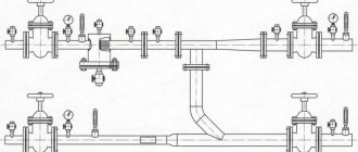
Selecting the location for inserting the device into the system
The installation of the circulation pump is supposed to be in the area immediately after the heat generator, not reaching the first branch line. The chosen pipeline does not matter - it can be either a supply or a return line.
Where can I put the pump?
Modern models of household heating units, made of high-quality materials, can withstand temperatures of a maximum of 100 °C. However, most systems are not designed for higher heating of the coolant.
Its performance will be equally effective on both the supply and return branches.
- The density of water when heated to 50 °C is 987 kg/m3, and at 70 degrees – 977.9 kg/m3;
- The heating unit is capable of generating hydrostatic pressure of 4-6 m of water column and pumping almost 1 ton of coolant per hour.
From this we can conclude: the insignificant difference of 9 kg/m 3 between the statistical pressure of the moving coolant and the return does not affect the quality of space heating.
Are there exceptions to the rules?
As an exception, inexpensive solid fuel boilers - with a direct combustion type - can serve. Their device does not provide automation, so at the moment of overheating, the coolant begins to boil.
Problems begin to arise if the electric pump installed in the supply line begins to fill with hot water and steam.
The coolant penetrates through the housing with the impeller and the following occurs:
- Due to the action of gases on the impeller of the pumping device, the efficiency of the unit decreases. As a result, the coolant circulation rate coefficient is significantly reduced.
- An insufficient amount of cold liquid enters the expansion tank located near the suction pipe. The overheating of the mechanism increases and even more steam is formed.
- A large amount of steam entering the impeller completely stops the movement of warm water along the line. Due to the increase in pressure, the safety valve is triggered. Steam is released directly into the boiler room. An emergency situation is being created.
- If the firewood is not extinguished at this moment, the valve will not be able to cope with the load and an explosion will occur.
In practice, no more than 5 minutes pass from the initial moment of overheating to the activation of the safety valve. If you install the circulation mechanism on the return branch, then the period of time during which steam enters the device increases to 30 minutes. This gap will be enough to eliminate the heat supply.
From this we can conclude that it is impractical and even dangerous to install a circulation device on the supply line. Pumps for solid fuel heat generators are best installed in the return pipeline. However, this requirement does not apply to automated systems.
Heating with a group of separate lines
If the heating system is divided into two separate lines, heating the right and left sides of the cottage or several floors, it would be more practical to install an individual pump for each of the branches.
When installing a separate device for the heating line on the second floor, it becomes possible to save money by adjusting the required operating mode. Due to the fact that heat has the property of rising, it will always be warmer on the second floor. This will reduce the coolant circulation rate.
The pump is inserted in the same way - in the area located immediately after the heat generator before the first branch in this heating circuit. Typically, when installing two units in a two-story house, fuel consumption for servicing the upper floor will be significantly less.
About installation and its features
A thermostatic type valve is installed on the supply part of the regulator pipeline. It is important to maintain a horizontal position for the heating device head. Exposure to direct sunlight and heat in large quantities is unacceptable.
Radiators cannot perform their functions properly if they are covered with curtains or crowded with furniture. In such a situation, a zone with an almost complete lack of sensitivity appears. This means that there is no contact with the environment.
Otherwise
If it is impossible to install the heating system in any other way, you will have to use remote control sensors that have a sensitive overlay element. So-called mini heating regulators are also designed for installation in niches.
Experts recommend installing a special shut-off valve on the return line of the heating radiator. Then you will not have to disconnect the entire heating system from the riser if you need to clean the battery or dismantle it.
The pump thermostat must be fully opened when the heating season ends. After this, no excess sediment will form on the valve seat; the device itself simply turns counterclockwise.
There are several thermal modes with which different types of pump devices can operate.
- summer - 28 °C;
- bathroom - 24 °C;
- living room - 20 °C;
- bedroom - 16 °C;
- internal corridor - 11 °C;
- frost protection - 7 °C.
It is necessary to adjust the thermostat for the pump before starting active operation. At this stage, additional hydraulic resistance is created. It is necessary to smoothly adjust the throttle mechanism to achieve the desired result of the pump.
The battery check valve and the battery inlet valve are equally good at accomplishing this same task.
Automation devices for pumps
The complex includes several separate units - a thermostat, a relay, and an uninterruptible power supply (UPS). The equipment is required to maintain the uninterrupted operation of heat pumps, as well as to determine the heating mode of the coolant that is transported along the main line.
Advice! A thermostat for a heating circulation pump is useful not only in an autonomous system, but also in a centralized one (in apartments). The device is installed on the radiator and serves to correct the intensity of coolant transportation in the radiator.
Features and purpose of thermostats
The device is designed to control the heating of the coolant and combines the functions of a shut-off valve and a thermoelement.
Operating principle of the temperature sensor:
- reading information from the temperature sensor, which is needed to determine the heating mode;
- comparison of sensor readings with preset heating settings that the user enters into the device menu, determining the temperature at which the pump turns on and off;
- putting the equipment into operation or turning off the pump.
The main point in determining the mode is hysteresis. This is the delay interval for the temperature indicator when starting and stopping the device. As soon as the process of heating the coolant begins, the hysteresis is added to the temperature indicators that determine the start of the pump, and when the liquid cools, the set hysteresis is subtracted.
Hysteresis is set manually; the owner himself can set the interval to 5 degrees or more. For example, in the mode settings there is a set temperature level of +50 C, a hysteresis of +7 C, then first the coolant warms up to +57 C, then the automation unit that controls the circulation pump starts the unit into operation. But to turn off the supercharger, the coolant needs to cool to +43 C (50-7).
Advice! The hysteresis should be set from +5 C so that the device does not start and turns off every minute, maintaining a heating accuracy of 1 degree. When selecting a pump, you need to look at the hysteresis settings in the firmware; it is more convenient to work with +/-1 degree minimum and +/-10 degrees maximum.
The temperature sensor is installed next to the boiler, and if the thermostat is set taking into account the temperature data in the room, then the boiler control devices must provide for changes in the heating temperature of the coolant.
Capabilities and principle of operation of an uninterruptible power supply
The circulation pump is a volatile equipment, so if the power supply is turned off, the device will not work. In order not to be left without heat, the owner needs to take care of an additional power source, which can be an uninterruptible power supply (UPS) or a generator. But the generator is noisy, but the support unit guarantees silence, while not being inferior to generators in functionality. The main thing is to choose the right source of direct current, taking into account the individual characteristics of the system.
Electronic type models
They are also briefly referred to as ET. These are automatic devices that help maintain a given temperature. If necessary, they can be used with any type of pump.
An electronic thermostat can automatically control system actuators such as valves and pumps, mixers, and boilers.
How does it all work?
The presence of a remote or built-in temperature sensor in the design becomes mandatory. It is installed in a place free from direct influence of other heating devices. This part is used to adjust the device.
The temperature sensor gives the ET information about what temperature is maintained in the environment. Currently, digital and analog versions of ET are produced.
The former have greater functionality, due to which they have become widespread.
In turn, digital type models are divided into two types:
- with open;
- or closed logic.
Diagram and operating principle of a heating circulation pump
A heat pump is a device that contains main components and auxiliary elements:
- the impeller (impeller) ensures transportation and pumping of liquid media through pipes;
- an electric motor starts the equipment;
- a pumping chamber with supply and pressure pipes that are connected to the main pipelines;
- a housing that protects the device from mechanical impact;
- terminal box for connecting electrical organs and control devices.
The best conditions, odds in lines for sporting events and this is in the application from 1xBet, you can use the link for your phone for free and receive a bonus using the MyAndroid promotional code.
The operating principle is simple:
- The coolant enters the pumping chamber. There is an inlet pipe for this.
- The flow is captured by an impeller, which is driven when the electric motor starts.
- Due to the increase in pressure, the coolant is sent to the coolant outlet pipe connected to the main line.
Thus, the diagram for the heating pump becomes extremely clear, there are no difficulties with functionality. It is only important to choose the type of equipment designed for the type of system installed at home.
Closed logic
The closed logic of the circulation pump device means that there is a rigid internal structure. The operating algorithm remains constant over time and does not change depending on the state of the environment.
This is quite possible for circulation pumping equipment. There are only a small number of programmable parameters that can be changed.
The composition of this kit, based on the operating principle of the heat pump, is as follows:
- – outdoor unit of the Mitsubishi Electric heat pump;
- – battery tank;
- – brazed plate heat exchanger with parameters suitable for the parameters of the external unit;
- - circulation pump;
- – flow switch to control water circulation in the system;
- – automation and control unit, consisting of: controller for controlling the external unit, circulation pump and additional equipment; automation panel for monitoring and controlling additional equipment.
In addition, you will need copper pipes, various fittings, shut-off and safety valves, and thermal insulation.
You can purchase each of the component parts of the system components for assembling a heat pump with your own hands from us.
Open logic
There are also freely programmable types of devices with open logic. They are also often found in circulation-type pumping products. Such devices can be easily adjusted to any environmental conditions and temperature conditions.
But managing them is quite difficult; special qualifications are required. That is why they are not widely used; in circulation-type devices, closed logic is most often found.
You should not save on purchasing a thermostat for your heating system, because this product significantly increases productivity and efficiency.
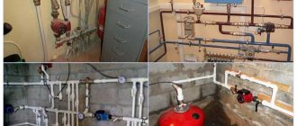
Schemes for different types of systems
Initially, it is necessary to determine the insertion area of the circulation device. With its help, the process of active movement of liquid is carried out - the flow passes through the boiler and is forcibly directed to the heating radiators.
To locate a household pump, it is necessary to determine the most convenient area so that it can be easily serviced. On the supply side, it is installed after the safety block and shut-off valves of the boiler.
On the return pipeline, the pump is placed after the expansion tank in front of the heat generator.
Due to the presence of various mechanical impurities in the water, for example, sand, problems may arise in the operation of the pumping mechanism. Particles contribute to jamming of the impeller, and in the worst case, stopping the motor. Therefore, you will need to install a strainer strainer directly in front of the unit.
Separately, it is worth mentioning the issue of an open-type heating system. It is capable of operating in two modes - with forced and gravity coolant circulation.
The second option is more suitable for areas with frequent power outages. This is much more economical than purchasing an uninterruptible power supply or generator. In this case, the unit with shut-off valves must be installed on the bypass, and a tap must be inserted into the direct line.
In stores you can find ready-made units with a bypass. In place of the flow tap, there is a spring-loaded non-return valve. This solution is not recommended - the valve produces a resistance force of 0.1 Bar, which is considered a large indicator for a gravity-type circulation system.
Conclusions and useful video on the topic
There should not be any particular difficulties with installing the thermostat. You just need to choose it correctly for a specific heating system. And the selected video materials will definitely help you with this.
Video #1. Connecting a room thermostat to a gas boiler in all its nuances:
Video #2. Wall thermostat review:
Video #3. Technology for incorporating a contact thermostat into a system with a circulation pump:
An addition to a heating boiler in the form of a thermostat is a great way to save money on heating your home, increase living comfort and reduce wear and tear on equipment that heats the coolant. The money spent on thermostats pays off in one winter season.
In this case, you can choose either a simple mechanical option with manual control or a more advanced device with a programmer.
Would you like to tell us how a boiler with a thermostat works in your country house? Do you have information that will be useful to site visitors? Please write comments, ask questions, post photos related to the topic of the article in the block below.