Here you will learn:
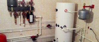
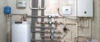
Indirect heating boilers are actively used in everyday life as productive devices for convenient and safe preparation of hot water. Using heat from traditional heating pipes for power, they are economical. Connecting an indirect heating boiler is carried out using several schemes described in this review - we will consider both complex and simple schemes. At the same time, we’ll figure out how to make the electrical connection of this unit.
What is an indirect heating boiler
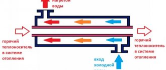
Its peculiarity is that the principle of operation is not based on heating water due to its own unit, but on heat exchange from external sources, such as fuel combustion, electrical resistance (resistance), contact with central heating, and the use of solar panels for energy processing. At its core, the boiler is a connecting link between the heart of the heating system (boiler) and all its vessels and arteries, correctly distributing the load and pressure on each branch. In this distributor, hot liquid passes through a metal spiral (coil) built into the storage tank. Heat exchange occurs through conduction between the coil and the cold water tank. A mandatory component of the boiler is thermal insulation, reminiscent in structure of a thermos to maintain the temperature inside the container, eliminating the loss of accumulated joules outside the device. The material for thermal protection is mainly polyurethane. The boiler circuit also includes a protective anode, an inspection hole, a bumper, and a submersible sleeve (for the temperature sensor).
Thanks to the heat exchanger, it is possible to heat water in a short period of time (up to 20 minutes from zero to 60 degrees). The only thing is that it is necessary to connect an indirect heating boiler with a boiler (usually gas) in order to be able to carry out such rapid heating.
Emergency options
Every piping scheme must include a circuit in case of emergency situations. His task includes:
— protection against pressure drops;
— protection against temperature increases above the permitted limit;
— prevention of moisture formation.
Safety valve in the harness
Its task is precisely to relieve excess pressure from the system. It is mounted at the boiler outlet separately or as part of a safety group.
Emergency heat exchanger in the solid fuel boiler connection system
Its task is most responsible - to prevent overheating of both the boiler and the system in general. Overheating can happen for 2 reasons:
— too much fuel was loaded into the boiler. The heat received exceeded the demand.
— the electricity was turned off and the pump stopped working.
For normal operation of this circuit, it is also necessary to install a temperature sensor with a valve and a cooling unit in the water supply pipe to the boiler. As soon as the coolant temperature exceeds the maximum allowed, the sensor signals this and provokes the opening of the valve.
After the valve is activated, water begins to fill the cooling unit, reducing the temperature of the main coolant.
Auxiliary heating circuit for a solid fuel boiler
One of the options for cooling the system. Its peculiarity is that you will need to connect a storage tank for the DHW circuit.
This scheme will work as follows: in normal operating mode, the pump will operate, creating a certain pressure. It will prevent the auxiliary circuit from coming into operation. But as soon as the electricity is turned off, the pump will stop working, the pressure will disappear, and the backup circuit will come into operation.
Result: the water temperature in the system will drop to the desired value.
Let’s say right away that this scheme is suitable for absolutely any type of heating system!
This mixer maintains the lowest temperature of the coolant at the inlet to the boiler so that condensation does not form on the walls of the device. what we talked about at the very beginning of the article. Thus, in a solid fuel boiler this is one of the most necessary components!
The mixer is installed on the return pipe using a bypass.
If the temperature in the return pipe is low (below the set value), the thermomixer will provide an influx of hot water.
Connection progress for an indirect heating boiler
After choosing a circuit, it becomes clear what equipment will be required. In addition to the main devices, you may need valves, ball valves, distribution combs, valves (three-way or check).
Procedure:
- prepare the installation site (on the floor or on the wall);
- make the wiring, marking the hot/cold water outlets in red/blue;
- install a tee and a pressure relief valve, securing the connections with sealant;
- screw on the hot (top) and cold (bottom) water taps;
- connection to a power source, install a thermostat and automation;
- select heating mode;
- test the connection.
These are general guidelines needed to present the scope of work. When connecting a specific model, you must follow the instructions that come with the kit.
The best known manufacturers and models: characteristics and prices
Now I want to talk about the most popular and reliable three-way valves to make it easier for you to choose the right model.
Manufacturer from China. It offers fairly high-quality products for heating and water supply at a relatively low price.
| Photo | Model | Specifications | Peculiarities | Cost, rub. |
| (ZEISSLER) BL3110C04 | Material: brass Temperature range: 35-60 Operating pressure: 2-5 bar Diameter: 1 inch | Mixing, for heating and hot water supply | 2 300-3 000 | |
| BL8803 | Material: brass Temperature range: 38-60 Operating pressure: 3-10 bar Diameter: ¾ inch | Mixing, external connection via American connection | 2 800-3 500 | |
| BL8804A | Material: brass Temperature range: 38-60 Operating pressure: 3-10 bar Diameter: 1 inch | Mixing, electrically driven | 2 000-2 600 |
This Swedish company produces various models of valves and controllers. I believe that the products from this company are of the highest quality. Although expensive.
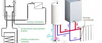
How does a boiler work in tandem with a non-volatile boiler?
If a non-volatile boiler is used as a heating source, in order for the hot water supply to be a priority, the boiler must be located above the radiators. This is easy to do if the model is wall-mounted. The best position is when the bottom of the hot water tank is higher than the heating boiler and radiators.
In a floor-standing model, the water will heat up, but it will take much longer. In addition, the water at the bottom of the tank will remain unheated. Its temperature will not exceed the return heating level in the heating system. With this scheme, the coolant flows by gravity, with gravity acting as the driving force. There is an installation method in which a circulation pump is connected to the boiler. But this is not a solution, because if there is no electricity, the water will not heat up. Experts have developed several schemes tailored to gravity heating systems.
The trick is that the diameter of the pipe intended for the water heater circuit is taken one step larger than the diameter of the heating pipe. According to the laws of physics, the coolant will “choose” a pipe with a large diameter, that is, the boiler will be a priority.
In another method, a thermostatic head with a built-in sensor, powered by batteries, is installed in the heating system. Everything is very simple: using the thermohead regulator, you set the desired level of water heating. While the water is cold, the thermostat opens the way for water to enter the boiler. As soon as the water warms up, the coolant is directed to the heating circuit.
Installation with electric or gas unit
Two heat generators can be installed in one heating system, the main one is a solid fuel unit, and the additional one is a boiler running on gas or electricity. This option is convenient because at night you can turn on the boiler, which operates in automatic mode. Gas in cylinders is inconvenient to use as the main energy carrier due to the need to take care of regular fuel supplies. Electricity is the most expensive energy source and it is most profitable to operate such a boiler unit only at night if the region has a system of cheap night tariffs.
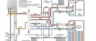
How to connect solid fuel and gas boilers into one heating system for a large house? The simplest option is to connect two heat generators in parallel through a heat accumulator, which will additionally serve as a hydraulic separator.
The gas boiler operates in standby mode while the water in the buffer tank is heated by the solid fuel unit. After the fuel burns out, the coolant begins to cool, and as soon as the temperature sensor transmits the corresponding signal to the gas unit controller, it automatically turns on. When a solid fuel heat generator is restarted, the reverse process occurs - heating the coolant above a certain temperature leads to the gas burner turning off.
A system with an electric boiler in large houses is installed according to a similar principle. But for small private houses, a simpler and cheaper option for connecting a TT and an electric boiler is relevant (see diagram).
Connection diagram for solid fuel boiler and electric boiler
Boiler units are connected in parallel with the installation of check valves at each outlet. The electric boiler is equipped with a built-in circulation pump, which cannot be turned off, so for a solid fuel heat generator it is necessary to select a more powerful pump so that the TT boiler has an advantage over the electric one when operating together.
The system is being supplemented
:
- a thermostat that turns off the boiler’s TT circulation pump when the coolant cools down;
- a room temperature sensor, which turns on the electric boiler when the room temperature drops after the fuel burns out in the TT unit.
Method of primary and secondary rings
How to connect two boilers into one system using a minimum amount of electronics? The use of the method of primary and secondary circulation rings allows for joint piping of the CT of the unit and the electric boiler. Hydraulic separation of flows is carried out without installing a hydraulic arrow.
Option for connecting two types of boilers to one heating system
Both boilers, the DHW boiler, as well as all heating circuits, are connected by both supply and return pipelines to a single circulation ring - they are the primary one. The minimum pressure drop is ensured by the small distance between each pair of connections (no more than 300 mm). The pressure of the pump installed on the main circuit ensures the movement of the coolant along the primary ring, while the flow intensity is not affected by the pumps of the secondary circuits (to which heat consumers are connected).
For the system to function properly, it is necessary to perform complex hydraulic calculations and select the optimal pipeline diameter for all circuits
It is also important to calculate the pump performance. The actual performance of the pumping unit on the main circuit must exceed the coolant flow rate on the most “volumetric” secondary circuit
Both boilers are equipped with shut-off thermostats so that they can operate instead of each other.
Strapping stages
First, an installation diagram is drawn taking into account the dimensions of the room and the selected locations for all devices. After this, holes for the heating boiler and boiler are marked and drilled. If the devices are floor-mounted, then it is advisable to make a small foundation for them according to the size of the buildings.
Next, propylene pipes are cut according to size and connected to each other with tees using a soldering iron. Pumps, taps, filters are installed and everything is combined into one system. If you have additional circuits, for example, on a hot floor, then a collector is installed that evenly distributes the coolant flows.
Connection diagram for a double-circuit boiler
An expansion tank and a safety complex are mandatory. When installing a safety group, you should take into account that if it works, water will flow out of it. Excess coolant goes into the expansion tank during expansion.
After all connections, water is introduced into the system and all connections are checked. If there are no leaks, then the boiler starts and the heating rate of the batteries is checked.
Closed type with natural circulation
It is also a fairly simple piping scheme with a small number of heat consumers.
The scheme is very similar to the open type. It is distinguished by the inclusion of a closed expansion tank with a membrane, which is installed on the return pipe. In addition, do not forget about the security group. Some models are already equipped with it in production. The expansion tank is designed for a volume of more than 10% of the total coolant volume.
There are several important points when lining a heating boiler with polypropylene. The pipe from the heat generator to the safety group is made of metal, then it is laid from polypropylene. Also, the section of the return pipe with an installed three-way valve and sensor is made of metal. Polypropylene has low thermal conductivity. If you install a three-way valve on it, it will respond with a delay to an increase in temperature, and the sensor will provide information incorrectly.
In general, the polypropylene piping system for a heating boiler is beneficial and quite practical.
Installation instructions for the recirculation system
It often happens that plumbing fixtures are located in the house at a considerable distance from the boiler or on the upper floors. In this case, the owners of the building usually have to wait until the water that has stagnated and cooled in the pipes drains from the taps in the bathrooms to get hot water. And this, of course, is inconvenient and not particularly economical.
This situation can be corrected by assembling a recirculation system in a country house. Installation of such a network is carried out approximately as follows:
- a tee is cut into the pipe supplying hot water to the consumer as close as possible to the consumer;
- a pipe of the required length is connected to the tee;
- the extended line is connected to the boiler through the recirculation pipe;
- Next to the boiler, at the nozzle, an additional pump of not too high power crashes into the circuit.
When using such a scheme, the water in the pipes between the boiler and the consumer, after turning on the pump in the electrical network, will not stagnate and, accordingly, will be cooled. That is, residents of the house will be able to use hot water immediately after unscrewing the tap valves.
Useful qualities
The volume of the device can vary from 30 to 1500 liters, it depends on its purpose. Units with a volume of up to 200 liters are available as wall-mounted units, larger units – as floor-mounted units. As a rule, a 200-liter boiler is enough to satisfy the hot water needs of one family. The efficiency of this device is high and is about 90%.
Modern models are equipped with additional electrical elements, heating elements, or have the ability to connect them. This allows you to use them as an additional source of water heating and turn off the boiler in hot months, which significantly increases the service life of the boiler.
Schemes and rules for connecting BKN
The connection diagram and installation features of an indirect heating boiler depend on the class of the device and the heating system in the house. It is necessary to choose the right installation location, focusing on the location of the boiler, pump insertion and existing wiring. Let's try to figure out what needs to be taken into account when installing heating equipment.
#1: Trim method with three-way valve
This is one of the most popular schemes, since when it is used, there is a parallel connection of the heating system and the BKN, equipped with shut-off valves. The boiler must be installed near the boiler, a circulation pump must be installed in the supply, then a three-way valve. This scheme is successfully used if several heating devices are used, for example, two different boilers.
A three-way valve is a kind of switch that is controlled by a thermal relay. When the temperature drops, the automation is activated, and the coolant flow from the heating circuit is redirected to the BKN (+)
Essentially, this is a priority system that ensures rapid heating of water in the boiler when the radiators are completely turned off for a while. As soon as the temperature rises to the set value, the three-way valve is activated again and returns the coolant to its previous direction - to the heating system. This piping method is useful for those who use the boiler constantly.
#2: Option with two circulation pumps
If the boiler is rarely used (for example, seasonally or on weekends) or there is a need for water whose temperature is lower than in the heating system, use a circuit with two circulation pumps. The first is installed on the supply pipe, directly in front of the BKN, the second - on the heating circuit.
The circulation pump is powered through a thermal relay, so it starts to operate only when the temperature drops below the required one. Heating accelerates when forced circulation is turned on (+)
There is no three-way valve in this scheme; the piping is equipped using simple connecting tees.
#3: Piping with hydraulic boom
This connection is used for volumetric boilers (200 liters or more) and branched heating systems with many additional circuits. An example is the heating system in a two-story house, where, in addition to a multi-circuit radiator network, heated floors are used.
A hydraulic distributor (hydraulic arrow) is necessary to simplify the layout of the heating system and avoid installing recirculation pumps on each heating branch (+)
The water gun equipment allows you to avoid thermal shock, since the water pressure in each circuit will be the same. It is quite difficult to make the piping according to this scheme yourself, so it is better to turn to professional installers.
#4: Using coolant recirculation
Recirculation is useful when there is a circuit that requires a constant supply of hot water - for example, a heated towel rail. If it is connected to the heating system, the coolant will constantly circulate, and the dryer will function and at the same time serve as a heating device.
The use of recirculation has one big advantage - you don’t need to wait for the water to heat up to the desired temperature, it will always be hot (+)
But this scheme also has disadvantages. The main one is an increase in fuel costs, because constant heating of the water cooled in the circuit is required. The second disadvantage is mixing water in the boiler. Typically, hot water is located in the upper part, and from there it flows to the water supply points, where it is mixed with cold water, as a result of which the outlet temperature is slightly lower.
There are models of boilers with built-in recirculation, that is, with ready-made connections for connecting a heated towel rail. But it’s cheaper to buy a regular tank using tees for connection.
#5: System for working with a non-volatile boiler
A distinctive feature of this scheme is the installation of the boiler at a higher level than the boiler and heating appliances. Preference is given to wall-mounted models that can be hung at a height of 1 m above the floor.
Floor-standing models specifically within this scheme are inferior to wall-mounted ones in heating speed and quality. The water temperature is much lower (about the same as in the return pipeline), therefore, the supply of hot water is less (+)
The non-volatile type of heating is based on the application of the laws of gravity, therefore, the coolant will circulate even when the electricity is turned off. In normal mode, you can connect circulation pumps.
Rules for installing fittings
Typically, the manufacturer indicates the movement of water flow with arrows on the body of a three-way valve. Using these guidelines, you can determine the type of valve. Connection to the system occurs as indicated by the arrows. The installation location should be convenient for subsequent adjustments or replacement in case of malfunction. Both return and supply are suitable for this. But read the instructions carefully, since not all valves can be installed for supply.
Since most of the valves inside are made of ceramic, they do not handle dirty water well. Therefore, it is better to install a filter in front of the valve. If this is not done, the device may become clogged. In some cases, it is enough to clean it, but sometimes even this does not save. Therefore, you should not skimp on filters.
The electric drive should not be located at the bottom, and mechanical thermostatic mixers are also not recommended to be installed this way, only vertically. But I can say from my own experience that in some cases this is possible. And reviews from some owners confirm this.
Connection features
An indirect heating boiler is a storage tank, inside of which one or more tubular heat exchangers are located. The hot coolant from the boiler circulates through the coil and heats water in sufficient volume for domestic and economic needs.
The principle of operation of the water heater is simple; difficulties arise during installation and wiring of heating equipment.
Therefore, it would not be amiss to find out the specifics of connecting a water heating device before starting work:
- The closer the boiler is located to the boiler, the more efficient the heat exchange from the heating system occurs.
- The installation of the water heater must be carried out in accordance with the manufacturer’s recommendations - wall-mounted models are attached to the wall, floor-standing models are installed on the floor.
- The flow of cold water should be supplied through the lower pipe, and the intake of hot water through the upper, then the recirculation point will be in the center of the container itself.
- The pipes for the coolant inlet and outlet should “look” towards the heating device. The movement of hot water or antifreeze along the coil should be from top to bottom.
Compliance with these simple rules guarantees the efficient operation of the boiler-boiler system, the efficiency of the heater will reach its maximum and there will be enough hot water for all consumers.
Servo drive: device and principle of operation
As usual, for clarity, let’s look at the servo drive device according to the figure:
Servo drive device
As you can see, the following components are located inside the servo drive:
- Electric motor.
- A gearbox consisting of several gears.
- The output shaft by which an actuator rotates a valve or other device.
- The potentiometer is the same negative feedback that controls the angle of rotation of the shaft.
- Control electronics, which is located on the printed circuit board.
- The wire through which the supply voltage (220 or 24 V) and the control signal are supplied.
Servo control signal
Let's now take a closer look at the control signal.
The servo drive is controlled by a pulse signal with variable pulse width.
For those who don’t know what we’re talking about, here’s another picture:
That is, the pulse width (in time) determines the magnitude of the shaft rotation angle.
Setting up such control signals is not trivial and depends on the specific drive.
The number of control signals depends on how many positions the output shaft can occupy.
The servo drive can be two-position (2 control signals), three-position (3 control signals) and so on.
Common installation mistakes
During installation or during the commissioning process, you should try to avoid a number of mistakes:
- The boiler and boiler are installed far from each other. Their installation should not only be done as close to each other as possible. But, to simplify installation, the pipes are positioned correctly.
- Incorrect connection of the pipeline with the coolant.
- Incorrect installation of the circulation pump.
Proper installation, adjustment and configuration guarantee a stable hot water supply and allow all systems and devices to operate normally. This will prevent wear of parts and save on premature repairs.
Why do you need a buffer tank for a TT or electric boiler?
- after the TT boiler is turned off due to burning of wood or coal, at night, heating of the building continues;
- overheating and boiling of the coolant (a common occurrence during the operation of a high-pressure boiler) is eliminated;
- when installing a storage tank with a DHW circuit, you can provide hot water supply to your home;
- a tank with two heat exchangers can be simultaneously connected to a boiler, hot water supply system and solar collectors or geothermal pump.
In the case of parallel connection of an electric and solid fuel boiler into a single heating network, the storage tank plays the role of a heat accumulator and a hydraulic separator.
| Living area / battery life | 8 o'clock | 10 o'clock | 12 o'clock | 14 o'clock | 16 o'clock |
| 100 m² | 587 l | 734 l | 881 l | 1028 l | 1175 l |
| 150 m² | 880 l | 1101 l | 1321 l | 1542 l | 1762 l |
| 200 m² | 1174 l | 1468 l | 1762 l | 2056 l | 2350 l |
How to choose an indirect heating boiler
In principle, choosing a BKN is very similar to choosing a conventional storage boiler. But let's briefly repeat the main points.
Volume is the very first thing to choose. Let's simplify your task: on average, 1 family member should have 40-80 liters of water. There will be no problems with selecting a model of suitable capacity. Today, the indirect heating boiler market offers models with volumes from 200 l to 1500 l.
Water flow through the heating circuit - be sure to look at this characteristic from the model data sheet.
The value of this characteristic should be no more than 40% of the total volume of water that passes through the heating boiler.
The material of the tank and thermal insulation - you understand, the best choice for the tank is stainless steel. It is better to choose polyurethane foam or mineral wool as insulation - they have the best heat-insulating properties.
Experts do not recommend choosing models with foam thermal insulation. It doesn't hold heat very well.
Compatibility with heating equipment
Indirect heating boilers work without problems with any heating system that supplies hot water - as long as its power is sufficient. As noted above, solid fuel boilers that operate on all available types of fuel are an excellent option. However, devices running on gas, electricity or liquid fuel will also be quite effective.
The installation of the tank itself is not very complicated, but the connection diagram for an indirect heating boiler is no different in simplicity. When choosing a model with controls, there will be no special problems, but with simplified products you will have to tinker so that the boiler working in conjunction with them can work with both heating and water supply.
Boiler recirculation diagram
Recirculation of water in the DHW system is necessary in order to provide hot water to any point in the system without additional spillage. To do this, a circuit is installed through which water from the boiler passes throughout the entire system, and then returns back to the boiler. Recirculation is carried out using a small pump that operates completely silently. This system helps maintain a stable temperature of hot water anywhere in the house.
Among the common recycling schemes, there are several main options:
- Installation of a three-way or servo-motorized valve. This method is used for wall-mounted and floor-mounted boiler models. Two pipes (two circuits) are connected to the boiler. One circuit is intended for heating, the other for hot water. The water heater in this system acts as the main coolant. When the water temperature drops, a servo-driven or three-way valve is used, which begins to work to heat the water. The heating is turned off at this time. After heating the water to the desired temperature, heating is resumed;
- Installation of two circulation pumps in one system. With this scheme, one of the pumps is designed to recirculate hot water through the heating system, and the other - through the boiler circuit. This system initially ensures normal water temperature in the boiler, and then in the heating system. A feature of this scheme is the presence of a thermostat and a mode switch, which allows you to turn off, if necessary, one of the systems;
- Application of a hydraulic arrow. It is used if there are more than two circuits in the house (heating, hot water, heated floor). This scheme is aimed at heating water, due to which all circuits are heated. This system has a significant drawback - when analyzing water. The coolant may not be able to meet the needs of all people at the same time.
The choice of method of heating water and heating, as well as methods of its recirculation through the boiler, must be carried out in accordance with clear calculations of all consumers and the power of the coolant. Among the main schemes, boilers with three-way or servo-actuated valves have an advantage.
Pump selection
How to choose the device we are interested in?
To answer this question, you first need to understand how the circulation pump works in a water supply system.
He will have to perform two functions:
- Make water move, overcoming the hydraulic resistance of a closed circuit. This resistance depends linearly on the length of the circuit and vice versa on its diameter (the smaller the cross-section of the pipe, the more it slows down the water). In addition, the hydraulic resistance is strongly influenced by the roughness coefficient of the pipes: the smoother the walls of the filling or liner, the less resistance it has to the movement of water;
Smooth inner pipe walls mean minimal pressure loss
Reference: for all types of polymer and metal-polymer pipes the roughness coefficient is minimal and does not change throughout the entire period of their operation. For steel pipes it is not only high initially, but also increases over time due to corrosion of the walls and their overgrowing with lime deposits.
Overgrowing of walls is one of the problems of steel water pipelines
- In addition, the hot water circulation pump must ensure a certain speed of water movement and, accordingly, a minimum temperature difference between the beginning and end of the DHW circuit.
Hint: from the technical characteristics of the device, pressure is responsible for the first function, and productivity for the second.
In general, when installing a hot water supply system in a private house with your own hands, you can do without complex calculations for two reasons:
- The pressure driving hot water in the DHW circulation system or coolant in the heating system of an apartment building is only 1-2 meters. The lowest-power circulation pumps for water supply have a pressure of 1.2 meters - with a obviously lower hydraulic resistance of the circuit;
The difference between the heating threads is only 0.2 kgf/cm2, or 2 meters of pressure
- The volume of the water supply is small, and, therefore, the required productivity is also small. For example, a pipe with a typical internal diameter of 15 mm for a cottage water supply and a length of 100 meters will have an internal volume of only 3.14 (pi) * 0.00752 (radius of the internal section of the pipe in meters squared) * 100 (pipe length in meters) = 0.0176625 m3, or 17 liters.
Formula for calculating the volume of a cylinder with known height and radius
The minimum performance of circulation pumps for hot water supply is calculated in cubic meters per hour and will obviously be excessive.
Practical conclusion: for the hot water supply circuit of a private home, you can safely buy the youngest circulation pump in the model range of your chosen manufacturer.
In the photo - circulation pump for water supply Grundfos UP 20-15 N 150. Pressure - 1.2 meters, productivity - 2.1 m3/hour
A caveat: for hot water supply, a pump with a brass rather than a cast iron body is preferable. The instruction is related to the much greater amount of oxygen in the water of the hot water system compared to heating: the corrosion resistance of cast iron is not absolute, and prolonged contact with oxygen-saturated hot water significantly reduces the life of the device.
Preferred body material is brass
Calculation scheme
How to calculate a circulation pump for hot water supply if you want to make sure its parameters meet your needs?
Here is a relatively simple diagram for calculating pump performance, suitable for pipelines with a diameter of up to 20 mm (3/4 inch):
The typical diameter of plastic and metal-plastic water supply connections is 20 mm
- We calculate heat loss in the pipeline. In heated rooms with the indicated diameter they can be taken equal to 7 watts per meter, in unheated rooms (subject to thermal insulation of the pipe) - 11 W/m. For our example, with a 100-meter hot water supply pipe laid in an unheated basement, the total losses will be 1100 watts;
- The normal temperature difference for the beginning and end of a circuit up to 200 meters long is considered to be 2 degrees, over 200 meters - 5-7 degrees;
The temperature at the beginning and end of the DHW circuit should not differ greatly
- Consumption with known heat loss and permissible temperature difference is calculated using the formula V=Q/(p*c*Dt).
Where:
- Q - heat loss,
- p is the density of water (1 kg/l);
- c is the specific heat capacity of water (1.2 W*h/(kg*K);
- Dt is the permissible temperature difference.
For our case, the calculated flow rate in liters per hour is 1100/(1*1.2*2)=458.
To convert this result into cubic meters per hour, which indicates pump performance, multiply it by 1000
Step-by-step strapping in gravity systems
The water heater is installed in networks of this type in such a way that it is located above the radiators. Therefore, for gravity systems, they usually purchase not floor-mounted, but wall-mounted suspended boilers.
The correct installation of water heaters in networks with natural coolant circulation includes the following steps:
- the supply from the boiler is connected to the boiler coil using a pipe of a larger diameter than in the heating system;
- then the heating system supply is cut into this segment between the boiler and the water heater;
- between the boiler and the resulting branch, a thermostatic head with an attached sensor, powered by batteries, is mounted;
- the boiler is connected to the boiler by a return pipe;
- a line for discharging cooled coolant from the radiators is cut into the return pipe;
- An expansion tank is installed closer to the boiler on the return line.
When using this scheme, water is heated due to the difference in the cross-section of the supply pipes of the boiler and the heating system. The water heater in this case is a priority. As soon as the water in the boiler warms up to a certain temperature, the sensor is triggered and the pipeline is closed. As a result, water begins to flow into the heating system.
Wiring a solid fuel boiler with an indirect heating boiler
Connecting a water heater with a solid fuel boiler solves two problems at once:
- obtaining hot water supply;
- obtaining a method for discharging coolant in the event of an accident.
Due to the fact that such a system places a thermostatic valve on the battery, comfort increases. But there is a danger of the boiler overheating. The same threat arises during power outages. If a boiler of increased capacity is installed, this process does not pose any danger. Because excess heat is spent on heating water in the water heating tank. Accordingly, for the normal operation of this system, a boiler with natural ventilation is needed.
See the following video for one of the options for connecting a solid fuel boiler to a boiler.
What is a servo and how does it work?
Let's start with a definition. A servo is an electric motor controlled through negative feedback.
In this case, the negative feedback will be a shaft angle sensor, which stops the shaft movement when the desired angle is reached.
To visualize the servo drive, look at the picture below:
Servo drive for three way valve
How to choose an indirect heating boiler
The main parameter of such a device is its usable volume. The numerical value of this parameter is influenced by many factors:
- the number of residents of the house consuming hot water;
- residents' habits;
- their mode of life, etc.
Based on “such parameters” it is difficult to determine the exact value of the volume. Therefore, when calculating the volume, take approximately 80 liters per resident. The range of volumes for devices of this type is quite wide: from 200 to 1500 liters. However, choosing a heater with a significant reserve volume is unprofitable, since energy costs will increase. And the device itself “increases in price” as its volume increases.
The second important parameter is the coolant flow through the heating circuit (data from the device data sheet). As a percentage, it should not be more than 40% of the total flow through the heating boiler.
You should also pay attention to the material from which the container is made and the quality of its manufacture. Heaters with a stainless steel tank have the greatest longevity and price
An important point may be the ability to dismantle the internal heat exchanger for cleaning.
Thermal insulation should be polyurethane foam or mineral wool.
The name of the heater manufacturer and the “geography” of its production, along with the listed factors, play a significant role in determining the price.
The choice is yours! The modern heating engineering market is saturated with offers of a wide range of parameters.
Manufacturing of an indirect heating boiler
The process of assembling a water heater may vary depending on the type of design, but in most cases, equipment for gas and electric boilers is manufactured in the following sequence:
- Two holes are drilled in a pre-prepared cylinder using an electric drill with a crown attachment. One hole will be located in the lower part and used for supplying cold water, the other - in the upper part for discharging hot water.
- The resulting holes are cleaned, fittings and ball valves are installed in them. Then another hole is drilled in the lower part, into which a tap is installed to drain stagnant water.
- To make a coil you will need a copper pipe with a diameter of 10 mm. It is better to make a spiral bend using a pipe bender. If such a tool is not available, then you can take any round piece - a large diameter pipe, a log, a barrel, etc.
- The coil is being manufactured according to the previous calculations. The ends of the heat exchanger are bent in one direction at a distance of 20–30 cm. To mount the coil, two holes are drilled in the bottom of the cylinder. Threaded fittings are installed and welded into them.
- Before installation, the coil is lowered into a bucket or large container with water and blown out. If the structure is sealed, then the coil is lowered into the cylinder, aligned with the inlet and outlet openings and welded.
- If the cylinder was cut in the middle, then an anode is mounted in the upper part. To do this, a hole is drilled into which a threaded nozzle is screwed in, and a magnesium anode is mounted into it. If the container is assembled from three separate parts - bottom, lid and central part, then the anode can be installed at the last stage.
- Thermal insulation material is installed on the outside of the boiler. It is best to use spray polyurethane. Before application, all pipes are protected with thick polyethylene and cloth. If funds are limited, then you can use regular polyurethane foam, which, after hardening, is wrapped in reflective insulation.
- Fastenings for hanging on brackets are welded to the back of the boiler. For floor-standing boilers, support legs made of angle steel or reinforcement are welded to the bottom of the equipment.
At the final stage, fittings and taps are screwed on and the top cover is mounted. If possible, you can not weld the lid, but make clamping fasteners from steel wire with a cross-section of 3 mm.
When making a boiler for use with solid fuel boilers, instead of a copper coil, a U-shaped steel pipe is used, which is mounted at the bottom of the device. From the side of the furnace or boiler, the pipe is connected to the outlet pipe. The pipe is taken out from the boiler and connected directly to the chimney.
Installation diagram with two pumps
Another common scheme for connecting an indirect heating boiler is using two pumps. In this scheme, two separate, parallel to each other, circuits are configured: heating and the boiler itself - each of them is equipped with its own recirculation pump.
Priority in this system is given to the boiler circuit, so the boiler system pump is mounted in front of the heating pump. A mandatory component of the circuit is a check valve, which prevents the two water flows from mixing and ensures the correct distribution of liquids along the circuits. Also, it cannot do without the already familiar temperature sensor, which sends signals to the valve, thereby controlling the operation of the pumps.
Installation diagram with two pumps
The piping scheme for a boiler device with two pumps is best suited for systems with two separate heating boilers. Each of them must have independent power and provide heating of the liquid in separate circuits: one boiler must be responsible for general heating of the home, and the second for heating boiler water for domestic use. In this case, the circuit functions as follows: when the water in the boiler tank cools to the lower level, the coolant flow is switched to heat it, and after reaching the programmed temperature it returns to the main heating circuit.
This type of piping is valued due to the rapid heating of water: due to the speed of operation of the equipment, when switching heating to the boiler circuit, the coolant in the main heating system will not have time to cool down.
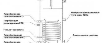
Design features of an indirect boiler
The indirect type boiler is a tank made of stainless steel. The inner walls of the container are covered with a special material, which not only protects the surface of the water heater from corrosion processes, but also reduces the concentration of harmful bacteria and microorganisms.
Diagram of an indirect type boiler with a single-circuit coil
Otherwise, a boiler of the simplest design consists of the following components:
- heat exchanger - a spiral pipe or smaller tank. Depending on the volume of the tank, it can be located in its upper and lower parts;
- inlet pipe - a fitting at the bottom of the device for supplying a pipe with cold running water;
- outlet pipe - fitting for connecting the hot water outlet pipe;
- magnesium anode - additional protection of the tank walls from corrosion processes;
- internal thermometer - a device for measuring the temperature of heating water;
- thermostat - a device that prevents equipment from overheating;
- control unit - rotary knob with divisions for setting the heating temperature;
- thermal insulation - a layer of insulating material that helps maintain the desired temperature of the heated water;
- outlet - valve for draining stagnant water;
- revision - a large diameter hole intended for maintenance, repair and modernization of the boiler.
The design of new tank models may differ slightly and have a number of modifications from manufacturers, but in general, any indirect type boiler consists of the listed elements.
Operating principle of the boiler
An indirect type boiler is part of the heating system and is connected directly to a gas, electric or solid fuel boiler, which heats the coolant using the energy released when fuel is burned.
The coolant circulates through the DHW system and passes through a heat exchanger located in the indirect heating boiler. Due to the release of thermal energy from the hot coolant, the cold water that fills the device’s tank is heated. From it, heated water is transported through an outlet through a pipe to the bathroom, kitchen and other rooms with plumbing equipment.
An indirect type boiler can work with any type of heating boiler
When the heating boiler is turned off or switched to an economical operating mode, the coolant quickly cools down. Thanks to the design of insulating the tank walls with urethane foam, the water in the tank cools very slowly. This allows you to use the entire volume of warm water for several more hours.
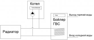
Connecting the boiler to a gas boiler
For the proper functioning of the boiler with a gas boiler, it contains a temperature sensor. For them to work together, a three-way valve is connected. The valve regulates the flow between the main circuit and the DHW circuit.
To a single-room gas boiler
For such a connection, a piping with two pumps is used. It is this that can replace the circuit with a three-way sensor. The main thing is to separate the coolant flows. In this case, it would be more correct to say that the two circuits operate synchronously.
To a double-circuit gas boiler
The main components of this connection scheme will be two magnetic valves. The bottom line is this - the boiler is used as a buffer. Cold water comes from the water supply network. The DHW inlet valve is closed. If you open it, water will first flow from the buffer, which is the boiler. The buffer contains heated water, the consumption of which is regulated by the capacity of the boiler and the set temperature.
Subtleties of installing system components
Having decided on the method of connecting a gas boiler and an electric boiler, you need to carefully think through and draw up a wiring diagram, and then proceed with installation.
Stage #1 - connecting a gas boiler
This stage should be entrusted to professionals: like any other gas equipment, only professionals certified by the gas service have the right to connect a gas boiler. This is due to the fact that even minor errors in installation and configuration are fraught with serious consequences.
It is quite possible to get confused in the variety of outputs of a double-circuit boiler, and if you start an incorrectly connected boiler, expensive equipment may fail
If a water supply or sewer leak threatens you with a puddle, a maximum of a couple of centimeters of water on the floor, then an error in connecting a gas boiler threatens a fire, explosion or poisoning by combustion products.
We reviewed installation diagrams for a double-circuit gas boiler in this material.
Stage #2 - boiler installation
An electric boiler operating in conjunction with a gas boiler is connected in the same way as for standard use. The only difference is that not cold water is supplied from the water supply, but hot water from the boiler.
When planning a hot water supply scheme with a boiler and boiler, be sure to set the latter’s thermostat to a lower temperature than in the boiler
Step-by-step instructions for installing a boiler are discussed below:
Installing the boiler and boiler is the main, simplest and most important part of the work, but this is only the beginning. For their effective interaction, it is necessary to perform the piping according to a pre-selected pattern. We will talk about the elements of such schemes further.
Stage #3 - connections and additional equipment
The first thing any water-related system should begin with is installing a filter to clean it.
Installing a mechanical water purification filter will prevent small solid particles from entering the heating and water supply system and extend the life of the equipment
When choosing a filter, remember that the better it purifies water, the longer the boiler, boiler, and all other equipment will last. Otherwise, small particles from the water settle on the walls of the coil and tank, form scale on the heating element of the boiler, contribute to the destruction of the tank and lead to rapid failure of all parts of the system - from the boiler to the faucet in the kitchen.
However, it is also not worth choosing the most expensive filter that purifies tap water to drinking state - it is too expensive and irrational. A filtration system with 2 – 3 levels of mechanical purification of varying degrees, from coarse to fine, will be quite sufficient.
The filter is installed at the very beginning of the chain, before connecting the water supply to the boiler. Be careful with the direction of flow - it is usually indicated by arrows on the body.
During operation, do not forget to regularly change the filter cartridges, otherwise they cease to perform their function and may negatively affect the water pressure.
The second obvious and necessary equipment is ball valves. You need a lot of them, they are placed at each connection: in front of the filter, at the boiler inlet and outlet, on both boiler connection pipes, at each outlet from the hydraulic needle, in front of each water tap.
This number of cranes ensures safety and comfort of operation. At some point, every part of the system will require preventive maintenance, and possibly replacement, and the ability to turn off just that will be very important.
Expansion tanks are installed to compensate for pressure drops in the water supply or heating circuit caused by changes in water temperature - for safety
When organizing DHW through a boiler, an expansion tank is usually not required: in the event of a critical increase in pressure, the boiler safety valve will operate. But if the heating circuit is installed separately, such protection will not be superfluous.
In addition to the listed devices, as well as the hydraulic comb discussed above, check valves are installed on the pipelines, which do not allow the flow to reverse even when the pump is turned off, safety and three-way valves, and, if necessary, a pressure reducing valve to reduce pressure.