An axonometric heating diagram is performed for a graphical representation of the intra-house piping of radiators of an individual heating system. This includes all structural components: thermal energy source, pipelines, pumps, mud traps, air vents, shut-off and control valves.
Such a graphic document must contain the main characteristics of all elements of the system. Without knowledge of heating engineering and drawing and drawing skills, it is quite difficult to perform an axonometry of the heating distribution, since it will be necessary to take into account many interrelated points, and in addition make thermal engineering calculations. For large multi-storey heating facilities, such schemes should be designed by highly specialized thermal power engineers.
Rules and regulations for drawing up an axonometric diagram
Any as-built documentation, including drawings, is carried out according to a certain algorithm, using symbols and design rules. The axonometric diagram of heating, air conditioning and ventilation is no exception. Designers, if they do not use a computer program where all the data is already available, use several documents:
- GOST 21.206-93 SPDS;
- GOST 21.602-2003 SPDS.
Information for calculating the power of the ventilation system and other technical data are specified in SNiPs and GOSTs. From there such important parameters as the frequency of air exchange, standard values of temperature and humidity are taken. The composition and complexity of the axonometric diagram depend on them.
Rules
The axonometric diagram is made in two types: a sketch and a full-fledged drawing. There are few requirements for the sketch; it is not an official document. A full-fledged axonometric drawing is performed according to all the rules prescribed in state standards:
- Selecting a viewing angle. The designer's first priority is to find the optimal point. A floor plan is used for this. It is positioned so that the lower part is adjacent to the designer, the left hand looks at the first axis of the building, the right hand looks at the last axis. The facade, which is closer to the designer, or rather its left corner, is the starting point for the axonometric diagram.
- Determining the orientation of duct lines. Everything is simple here. Ventilation ducts running parallel to the wall of the building closest or farthest to us are drawn as a horizontal line parallel to the walls. Bends running perpendicular to our wall are drawn at an angle of 45 to the horizontal line. Vertical sections of the ventilation system are drawn vertically.
- Scaling. An axonometric diagram, with the exception of a handwritten sketch, is carried out to a certain scale. It does not change within one drawing. If the axonometry to scale does not fit on the sheet, then breaks are allowed (this is when the duct line in the drawing is broken using a dotted line).
Requirements
The axonometric diagram, like other parts of the ventilation project, is carried out in accordance with the requirements of state standards:
- Extension lines for air ducts. With their help, the geometric characteristics, shape, and power of each channel are shown. A footnote with a shelf is set aside from each duct. Above the shelf the section size, length, width, or diameter (in the case of a round channel) is indicated. Below the shelf is the power value in cubic meters.
- Height marks are drawn on the right or left side of the drawing. This is necessary for the correct orientation of the system in the building. The first mark corresponds to the level of the clean floor; all the others “dance” from it. Heights are indicated in millimeters. If the duct has a round cross-section, then it is anchored from the center of the section; if it is square or rectangular, then from the bottom edge.
- All equipment, including fans, fittings, heaters, recuperators, is indicated by symbols or in the form of outlines.
- Often, an axonometric diagram shows the outline of equipment. This is done in the case of using local ventilation with individual suction or umbrellas. Equipment may be designated by an outline with a leader and markings.
- Inspection hatches are marked on the diagram. They are tied to dimensional lines. A callout is drawn above each hatch, similar to air ducts. The brand of the product is indicated above the shelf, under its number in the design documentation.
- All additional equipment, sensors, and metering devices are included in the drawing. Conventions are used.
- The drawing indicates sections of air ducts with insulation or treated with a fire retardant compound.
- Complex ventilation systems on large construction sites run through the entire building. Places of transition through load-bearing walls, partitions, and floor slabs are marked. Each overlap is marked. The walls are marked using the building axes.
- Air ducts are marked. The supply ones are designated by the letter - P, the exhaust ones - V. After the letter there is a number indicating the serial number of the branch. Within one drawing there can be P1 and B1, that is, the numbers for supply and exhaust are duplicated.
- Fans are marked according to the lines on which they are installed.
- Scale designation. Axonometric diagrams are scaled. This must be indicated on the drawing. For example, 1:50, 1:100. Means that one dimensional unit in the drawing corresponds to 50 or 100 units in reality.
Regulatory Requirements
They are comprehensively set out in GOST 21.602-2003, which regulates the rules for drawing up documentation for building engineering systems (including heating). Let us highlight from the text of the document the main points that are directly related to our topic.
General provisions
Elements of heating systems are assigned designations consisting of markings and a serial number within a given diagram. What designations are used?
| An object | Designation |
| Heating riser | St |
| Main heating riser (vertical filling part) | Gst |
| Compensator | TO |
| Horizontal branch (lezhnevka) | GW |
| Temperature measuring device (thermometer) | T |
| Pressure measuring device (pressure gauge) | R |
For some graphic symbols, the document refers to related GOSTs:
- Pipelines should be designated according to GOST 21.206 - 93.
- Designations of check valves, throttles, gate valves, radiators, etc. can be found in GOST 21.205-93.
Fragment of the designation table from GOST 21.205 – 93.
In addition, among the general provisions there are a number of additional requirements for drawings.
- Elevations are indicated on extension lines or element outlines.
- The axonometric heating diagram can be made on a scale of 1:50, 1:100 and 1:200.
List of designated equipment and parameters
The diagram drawn up by yourself should indicate:
- Pipelines with diameters indicated.
- Thermal insulation of pipeline sections. It is depicted graphically.
- Levels of the axes of all pipelines relative to the zero mark.
- Filling slopes (of course, where they are needed - in gravity systems and upper filling houses).
In the gravity system, filling slopes are indicated.
- If there are gaps in the horizontal sections of the bottlings, the sizes of the sections.
- Supports, compensators and suspensions.
- Shut-off valves. And in this case, a remote shelf is used, above which the type and diameter (DN) of the reinforcement is indicated. Below is the designation of the item according to the catalog.
- Risers and benches (horizontal sections) with symbols.
- Radiators, convectors and other heating devices.
Their type and main parameters must be indicated:
- Number of sections of a sectional radiator.
- The number of sections (pipes) of the register and its length.
- Number and length of finned tubes.
- For other heating devices - their type.
- Designations of installations (boilers, furnaces with heat exchangers, heat pumps, elevator units, circulation pumps for heating, etc.).
- Embedded devices (oil cups for temperature control and taps for installing control valves that allow pressure to be measured).
- The instruments themselves for measuring system parameters and heat metering.
Specifications
The standard sets out a number of requirements not only for the drawings themselves, but also for the specifications for them.
The elements listed in the specifications must be entered in them in the following sequence:
- Heating equipment (boilers, radiators, etc.).
- Shut-off and control valves (valves, gate valves, throttles, check valves).
- Other elements of heating systems (sump traps, discharges).
- Embedded structures (oil cups and bends for control valves).
The photo shows a real elevator unit in the basement of an apartment building. Anything that can be stolen is removed.
- Pipelines (bottlings, risers, connections).
- Thermal insulation.
Pipelines are entered into the specification for each diameter (usually by increasing diameter). Various bends, flanges, crosspieces for welding and bolts are not included in the specification.
An example of a specification for a drawing of a heating manifold.
Design work
The general scheme of a sewerage system is an assembly of pipelines connected to plumbing on one side and to treatment facilities on the other. However, for the installation of a specific section of a drainage system, a detailed and accurate drawing is required. When calculating the project, it is necessary to ensure the requirements of SNiP, as well as sanitary standards for the placement of elements. Basic requirements for a drainage project:
- sufficient capacity with some reserve in case of extreme discharge of wastewater;
- correctly calculated configuration, maintained pipe slope;
- the route should be as straight as possible, without sharp turns;
- in the direction of flow of drains, pipes of smaller diameter should be connected to pipes of larger size, and not vice versa;
- the route must be equipped with the required number of inspection wells or inspection elements.
The scheme of the sewerage system is drawn up taking into account its size, purpose and specific use. The compiler’s task includes competent tracing, excluding sudden changes in the direction of the line. In addition, it is necessary to provide for the technologically correct arrangement of pipes and the appropriate position of the plumbing outlet elements. In the process of creating a project, an axonometric diagram of the sewerage system of a residential building is often used. It gives an idea of the spatial position of elements and pipelines. For complex structures with a multilayer structure, this version of the drawing is much more convenient and clearer.
Ground floor plan
This plan shows the risers of sanitary units located in the grooves of the main walls: water supply (StV1-1...StV1-3), sewer (StK1-1...StK1-3) and hot water supply (StV1-1...StV1-3). The diameters of these pipeline systems are also indicated.
Fragment of the ground floor plan
The designed pipeline networks, which are plotted on the plans, are the basis on which axonometric diagrams of plumbing systems are made. These diagrams provide a clearer picture of how the various elements of a building's piping systems are positioned in relation to each other.
Design of wastewater system and water supply units
Each of these systems is of great importance for the normal functioning of citizens. For this reason, the comfort of the residents, as well as the livability of the apartment or private house, directly depends on the competent drawing up of the drawing.
The waste system has a special role. Some residential property owners are of the opinion that the process of implementing such a system is very simple and will not cause difficulties. However, even the procedure for preparing project documentation is considered a large, responsible and labor-intensive process. If at this stage you do not provide for all the details and make even a minor miscalculation, then in future operation it will certainly appear. There are even situations when incorrectly used sewerage symbols on the drawings will lead to the complete unsuitability of the building for habitation of citizens.
Wastewater system design
Purpose of sewerage
The main purpose of the sewer system is to remove used water and solid waste from the apartment. Often these things have a very unpleasant odor, so the design of the drain must take into account hygiene standards and rules. Due to the fact that the sewer system discharges large volumes of water, fats and solid objects, the waste system must be constructed from proven and reliable parts that perform their intended purpose well over a long service life.
In addition, it is important to remember about force majeure circumstances. Therefore, symbols on water supply and sewerage diagrams according to the drawing should be placed so that if an unforeseen circumstance arises, it is possible to urgently make adjustments to the operation of the system
Features of drawings
When drawing up an axonometric diagram, pay attention to the following points:
- Plumbing and other fixtures connected to risers and the distribution network are reflected only when the necessary diagrams are not included in the attached documentation.
- The zero mark (first floor level) is shown on the risers by drawing a thin horizontal line. In the case of detailing the project, each of the nodes of the drawing is considered separately, reflecting it on an enlarged scale.
- If necessary, symbols of shut-off and control valves, watering taps and other system elements are added to sketches of diagrams and drawings of water supply networks and sewerage systems.
Rules and regulations for drawing up an axonometric diagram
Any as-built documentation, including drawings, is carried out according to a certain algorithm, using symbols and design rules. The axonometric diagram of heating, air conditioning and ventilation is no exception. Designers, if they do not use a computer program where all the data is already available, use several documents:
- GOST 21.206-93 SPDS;
- GOST 21.602-2003 SPDS.
Information for calculating the power of the ventilation system and other technical data are specified in SNiPs and GOSTs. From there such important parameters as the frequency of air exchange, standard values of temperature and humidity are taken. The composition and complexity of the axonometric diagram depend on them.
Rules
A complex version of the axonometric diagram. The axonometric diagram is made in two types: a sketch and a full-fledged drawing. There are few requirements for the sketch; it is not an official document. A full-fledged axonometric drawing is performed according to all the rules prescribed in state standards:
- Selecting a viewing angle. The designer's primary task is to find the optimal point. A floor plan is used for this. It is positioned so that the lower part is adjacent to the designer, the left hand looks at the first axis of the building, the right hand looks at the last axis. The facade, which is closer to the designer, or rather its left corner, is the starting point for the axonometric diagram.
- Determining the orientation of duct lines. Everything is simple here. Ventilation ducts running parallel to the wall of the building closest or farthest to us are drawn as a horizontal line parallel to the walls. Bends running perpendicular to our wall are drawn at an angle of 450 to the horizontal line. Vertical sections of the ventilation system are drawn vertically.
- Scaling. An axonometric diagram, with the exception of a handwritten sketch, is carried out to a certain scale. It does not change within one drawing. If the axonometry to scale does not fit on the sheet, then breaks are allowed (this is when the duct line in the drawing is broken using a dotted line).
Requirements
The axonometric diagram, like other parts of the ventilation project, is carried out in accordance with the requirements of state standards:
- Extension lines for air ducts. With their help, the geometric characteristics, shape, and power of each channel are shown. A footnote with a shelf is set aside from each duct. Above the shelf the section size, length, width, or diameter (in the case of a round channel) is indicated. Below the shelf is the power value in cubic meters.
- Height marks are drawn on the right or left side of the drawing. This is necessary for the correct orientation of the system in the building. The first mark corresponds to the level of the clean floor; all the others “dance” from it. Heights are indicated in millimeters. If the duct has a round cross-section, then it is anchored from the center of the section; if it is square or rectangular, then from the bottom edge.
- All equipment, including fans, fittings, heaters, recuperators, is indicated by symbols or in the form of outlines.
- Often, an axonometric diagram shows the outline of equipment. This is done in the case of using local ventilation with individual suction or umbrellas. Equipment may be designated by an outline with a leader and markings.
- Inspection hatches are marked on the diagram. They are tied to dimensional lines. A callout is drawn above each hatch, similar to air ducts. The brand of the product is indicated above the shelf, under its number in the design documentation.
- All additional equipment, sensors, and metering devices are included in the drawing. Conventions are used.
- The drawing indicates sections of air ducts with insulation or treated with a fire retardant compound.
- Complex ventilation systems on large construction sites run through the entire building. Places of transition through load-bearing walls, partitions, and floor slabs are marked. Each overlap is marked. The walls are marked using the building axes.
- Air ducts are marked. The supply ones are designated by the letter - P, the exhaust ones - V. After the letter there is a number indicating the serial number of the branch. Within one drawing there can be P1 and B1, that is, the numbers for supply and exhaust are duplicated.
- Fans are marked according to the lines on which they are installed.
- Scale designation. Axonometric diagrams are scaled. This must be indicated on the drawing. For example, 1:50, 1:100. Means that one dimensional unit in the drawing corresponds to 50 or 100 units in reality.
Compound
The diagram consists of a drawing and a table with symbols. The drawing must contain a sufficient amount of information to understand the operation of the ventilation system.
Legend
There are two types of schematic diagram - floor and cross section. The first one reflects the top view within one floor, the second one is an analogue of axonometry.
Each diagram necessarily includes symbols:
- Air ducts, connections between branches.
- Connection points for fans and air ducts.
- Air intake and supply points.
- Other equipment (recuperators, heaters).
All elements of the ventilation system contain callouts that briefly describe the model or name of the equipment.
Siphons for sewerage
Siphons are U-shaped pipes that must be installed in front of all plumbing fixtures: bathtub, washbasin, sink, toilet, etc. The shape of the siphon ensures that a certain amount of water accumulates in it, covering the entire cross-section. Water remains in its lower part even after its supply is completed, preventing gases from escaping from the system. During normal operation of the system, such protection is quite effective, but there are cases when siphons do not cope with their task. For example, if the plumbing is not used for a long time, the water in the siphon will simply evaporate, opening the way for unpleasant odors to escape. To avoid this, the drain holes of plumbing fixtures must be closed with a plug, especially in cases where a long break in their operation is planned.
Treatment plants
Various devices can be used as treatment facilities:
- cesspool;
- septic tank;
- biological treatment station.
Each device has its own positive and negative qualities. A cesspool is better suited for small houses or cottages where people appear seasonally. Biological treatment stations are quite expensive, but demonstrate very good performance. A septic tank is an optimal design that can be made with your own hands or purchased ready-made.
Conclusion
There are different schemes of sewer networks. The selection of elements for the sewer system is a personal matter for each homeowner. It is enough to know the basic rules by which a sewerage system diagram is created and to carry out all the work correctly. The created structure will ensure the removal of wastewater from the building and provide a certain degree of living comfort in a private house.
Basic rules for organizing internal sewerage
No other equipment should be connected to the sewer pipe between the toilet and the riser. This is due to the fact that during flushing, water will be sucked out of all siphons connected to the system. This is why the toilet must be connected to the riser with a separate connection. In order to better clean sewer pipes, their slope should be from 2 to 15 degrees, this corresponds to 2-15 centimeters per meter of length. You should definitely take care of the ventilation of the risers. Without it, an unpleasant odor will appear after a while. In addition, this will lead to the emptying of siphons and the appearance of air pockets in the pipes, preventing the drainage of water. Ventilation should take place separately from the general natural exhaust channel of the house. In order for the ventilation of the risers to work properly, it must be installed half a meter above the roof. A sewer aerator is perfect for this purpose; Sanitary fixtures located on the same floor must be connected to the riser above the toilet connection point. If the fixtures are lower, dirty water will get into them when the toilet is flushed. The riser must have a diameter of 10 centimeters (if a toilet is not connected to it, then it is possible to use a pipe from 5 centimeters). The riser must be soundproofed. To do this, it can be covered with plasterboard, placed in a wall niche or covered with mineral wool. Pipe bends should be made smooth, 30-60 degrees
It is strongly recommended to avoid 90 degree turns. Each riser must have an inspection hatch at the bottom. All sanitary fixtures, except the toilet, can be connected to a common pipe for discharging water into the sewer. It is important to install the outdoor pipe below freezing point. In addition, it needs to be insulated
An inspection well is installed next to the house for it. To prevent flooding, a sewer check valve is installed in the pipe. General tips for sewer design
To properly design a sewer system, it is important to take into account the location of the house and calculate the distance to the proposed cesspool
- The best option would be 5-10 meters
. - You also need to keep in mind that the law provides for the installation of a septic tank at a distance of 4 meters from the neighbor’s property.
- If you build a cesspool too close to your own home, this can lead to the destruction of the foundation. If you make a cesspool further than 10 meters from the house, this will cause blockages and other problems in the sewer system.
It will be necessary to order the drawing up of an axonometric diagram of the system, which will help identify and solve installation difficulties. You need to think about turns, pipe sizes, junctions, connections, angles of inclination and elevation.
How to reflect structural elements in electronic form
The fastest way to build a drawing is by cloning the entire diagram. To do this, select the “Insert” command, after which the integrated image is flipped. For the function to be executed, it is given a value equal to 45 degrees (the number is written in the program).
Having prepared the basis in the electronic version, where the risers are marked on the plan, they put symbols in the form of dots. To reflect all floors in the building, a vertical line is drawn. For the purpose of better perception, the diagram shows the floor panels.
Important! Don't make the slabs too long. Take advantage of the gap
A special feature of the axonometric sewerage diagram is the reflection of all elements of sanitary facilities: urinals, toilets, sinks, drains and other devices for carrying out hygienic procedures.
External sewerage
Plastic pipes are also used to arrange the external part of the sewer system. They are laid in a trench, the depth of which exceeds the depth of soil freezing (for more details: “Installation of external sewerage - options for installation scheme”). The bottom of the trench is covered with a dense layer of sand, after which pipes are laid out on it (here you need to remember the need to maintain a slope). Inspection hatches must be installed at pipe connection points. It would not hurt to install a check valve in the pipeline, which will prevent wastewater from returning to the internal sewer network.
Wikonanny rules
An example of the principle diagram for installing a ventilation system.
Ventilation schemes are usually drawn from the frontal isometric projection (axonometry). This design allows you to create the entire range of wind pipelines in three dimensions, so that, based on the plans or sections, the axonometric coordinate system contains a third of the whole, on which the height values are placed and. Current design programs provide the ability to clearly and quickly draw axonometric diagrams. Although it is not accessible to the skin, the result still needs to be seen on a paper nose. Therefore, such a diagram can be drawn in the hand from a sketch, a design, following a number of rules for drawing axonometric diagrams. By following them, you see a complete picture of the tide or exhaust system on the paper.
In accordance with the rules, it is necessary to choose the angle from which the façade will be, which is laid out on the plan below, the outer wall of which façade is designated by the first letter of the whole. If you are drawing a simple sketch of one location, then you can draw it out as carefully as possible, but remember that during the official preparation of documentation the chair will have to be reworked. The system's conductors should be applied according to the following principle:
- If the channel runs parallel to the façade specified for the design, it should be applied as a horizontal line;
- the wind duct perpendicular to this façade is drawn on the diagram at 45 degrees to the horizontal according to the same scale;
- vertical plots are marked with vertical lines.
Axonometry of the heating system
Axonometry of heating
Schemes are drawn for both small private houses and large industrial or public buildings. The design rules almost completely coincide with ventilation. Heating plans can be combined with ventilation and air conditioning; axonometry is performed separately. The rules are stated in GOST 21.602-2003 “Rules for the implementation of working documentation for heating, ventilation, air conditioning”:
- Drawing scale 1:50, 1:100, 1:200. If a sketch is made, it is selected individually. Individual elements and nodes are reduced by 1:10, 1:20, 1:50.
- If the length of the heating branch does not allow it to be included on the sheet at a given scale, then a break is indicated with a dotted line. The edges are marked with letters.
- All additional elements on the axonometric diagram are indicated by catchy signs. The use of contours is allowed.
Example of an axonometric diagram
Axonometry of the heating (heat supply) system includes:
- Pipelines with diameter indication and alphanumeric numbering.
- Pipeline installation height. Binding from the floor level of the first floor, basement or foundation.
- Direction and digital value of the slope.
- Dimensions of horizontal sections, only if there is a gap.
- Installation locations of shut-off valves with markings of each element.
- Pipe attachment points, indicating the type of fastener and document number.
- Vertical riser pipes. Marked as horizontal.
- Instruments for measuring pressure, temperature, counters.
- Heating radiators, their quantity, type and installation location.
This is not a complete set of requirements for axonometric diagrams of ventilation, heating and air conditioning. To avoid mistakes, calculate correctly and get a full-fledged project, high qualifications are required.
These are the kind of specialists who work here. Our organization operates in Moscow and the Moscow region, we also carry out orders from nearby regions and are considering options for remote cooperation. You will find ways to contact us on the “Contacts” page.
What to pay attention to when creating a sketch
Before reflecting the axonometric diagram of heating a room in paper or electronic form, a number of calculations are carried out. The diagram itself is compiled based on the collected data:
- heat demand values for building rooms;
- typologies of heating devices, their quantities for each room;
- basic decisions regarding the entire engineering network: the use of risers, calculation of hydraulic branches and circuits, the order of connecting elements of the heating system;
- characteristics of pipeline sections: diameters and lengths of pipe fragments, shut-off valves, thermal controllers, hydraulic regulators.
Having received the appropriate calculations, their indicators are entered into the diagram. The axonometric diagram of the heating system necessarily contains the technical characteristics of each of the network nodes (boilers and pumps used), the length and diameter of the pipes, heat consumption and information about other thermal properties of heating devices, such as radiators, convectors, registers.
When starting to work on an axonometric drawing, first of all, the main ring of coolant movement is determined - the path to the most distant element from the boiler and back.
To summarize what has been studied, we will say that axonometry is mandatory, regardless of the type of communication system for structures of any type of purpose. Having a graphical drawing in front of their eyes, installers quickly determine how much work needs to be done and what exactly the network looks like.
If a specialist understands the axonometric heating diagram, and the drawing itself is executed correctly without any errors, then during the implementation of the project it is possible to eliminate the occurrence of any difficulties associated with the installation of elements of the heating system, pipelines and other utility networks.
In order for the design, and then the installation of the water supply system, to be successful, it is necessary to correctly visualize the building itself and the communication branches inside it on a sheet or in electronic form. In this case, the graphical component of the project includes:
- general plan of the building;
- situational diagram;
- facade;
- plans for each floor;
- roof plan;
- axonometric diagrams: ventilation, heating, water supply;
- sections and other schematic diagrams.
Remember that when working with correctly designed axonometry, problems with the installation of utility networks do not arise in 99.9% of cases. That is why this stage is so important in designing a future house or high-rise building.
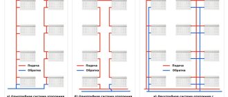
Heating schemes for private houses vary. For example, single- or double-circuit, with natural or forced circulation of the coolant, but when the phrase “axonometric diagram of the heating system” is uttered, many people wonder what kind of diagram this is. To know what an axonometric heating diagram is, you need to understand what axonometry is in principle.
An example of an axonometric heating diagram
Advantages and disadvantages
One of the main advantages of such a system is that each radiator can be connected via a separate circuit. This allows you to regulate each device separately, which is difficult to do in a single-pipe circuit. The system also has the following advantages:
- A thermostatic head can be installed on each heating radiator, which will automatically maintain the temperature balance in the entire system.
- Failure of any device will not affect the operation of the remaining batteries.
- This design can be used in the construction of both low-rise and high-rise buildings.
- Possibility to use pipes of smaller diameter.
In this video you will learn how to install a two-pipe heating system:
What is manifold piping
With manifold heating distribution, heating pipes are supplied to heating radiators from a single distribution unit. The dispensing unit (manifold) is a device with one input and several coolant outlets. Each coolant (water) outlet is independently closed with a shut-off valve. That is, if necessary, you can separately turn off any radiator of the heating system, regardless of the others.
For heating distribution from the collector to the heating radiators, it is carried out using plumbing pipes suitable for heating systems. For heating the following are used:
- steel heating pipes,
- metal-plastic pipes,
- polyethylene and polypropylene pipes (hot water supply),
- copper pipes.
Heating pipes are connected by special devices called fittings. Heating pipes can have one or two types of connection. This is how metal-plastic pipes are connected using crimp fittings and press fittings. Polypropylene pipes are connected using welding fittings. Copper pipes are connected using press fittings and crimp fittings. Steel pipes are connected using a classic threaded connection using cast or brass fittings.
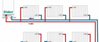
Scheme of two-pipe radiator heating of premises of a one-story house or apartment
<DIV><IMG style=”POSITION: absolute; LEFT: -9999px" alt="" src="https://mc.yandex.ru/watch/8100424″></DIV&amp ;amp;amp;gt;
Heating system class – Economy Plus Manual temperature control in the rooms. Radial two-pipe wiring. Two or more heating branches. Bottom connection of radiators
Advantages of the heating system:
Easy to install and configure. Aesthetic appearance of the premises due to the absence of visible pipelines. The system is hydraulically stable.
Disadvantages of the heating system:
Only manual temperature control in rooms. The pump is not overload protected. Pipe consumption is higher than with horizontal and vertical wiring. The need to lay pipelines in a screed and corrugated casing or insulation.
Operating conditions for the heating system:
Pressure in the heating system - up to 2.5 bar. Temperature of the heating system - up to 90°C. Temperature delta (difference between supply and return temperatures) 20°C. The area of the heated room is up to 250 m2. The power of the heating system is up to 30 kW.
The length of the supply pipeline from the collector to the last radiator is no more than 30 m.
Specification of main materials and equipment:
1A. Metal-plastic pipe d=16×2 (meterage depending on technical need. Subject to the use of pipes from other materials - polypropylene d=20mm, copper d=15mm) - no more than 60m per radiator. 1B. Metal-plastic pipe d=26×3-(meterage depending on technical need. Subject to the use of pipes from other materials - polypropylene d=32mm, copper d=22mm) - locally. 2. Ball valve 1″-1. 3. Direct flow valve 1″-1. 4. Membrane tank for heating, 24 liters-1. 5. Circulation pump with a set of nuts - Wilo Star RS 25/6 (or another manufacturer with a head of 6 m) - 1. 6.Check valve 1″-1. 7.Safety group up to 50kW 1″-1. 8. Manifold with shut-off valves (comb) 1″xl/2″ - according to the number of outlets (heating branches). 9. Manifold with control valves (comb) l"xl/2" - according to the number of outputs (heating branches). 10.Drain tap 1/2″-2. 11.Automatic air vent 1/2″-1. 12. Manifold tee 1′x 1/2″x 3/8″-2. 13.Distribution cabinet-1. 14. Connector for pipe 16×2.0 (or another diameter - depending on the pipes used) - according to the number of outlets. 15. Shut-off valve for mounting an air vent 1/2″-1. 16.Adapter 1/2″(BP)xЗ/8″(HP)-2. 17.Pair of brackets for manifolds - set. 18. Corrugated casing HDPE 16(25) - in place. 19. Manual air vent 1/2″ - locally (depending on the number of radiators). 20. Heating radiators - depending on the needs of the room. 21. Bottom radiator connection unit - locally (depending on the number of radiators). 22. Connecting pipe - in place. 23. Radiator plug 1″ - in place (depending on the number of radiators). 24. Manual air vent 1/2″ - in place (depending on the number of radiators). 25. Radiator foot 1″ x 1/2″ - (depending on the number of radiators). 26. Connector 16 (2.0) (or another diameter - depending on the pipes used) - in place.
Radiator heating diagram for a two-story house
Designations
Each element of the heating system and circuit has its own marking.
- P – supply systems, system installations, exhaust systems;
- B – installation of systems;
- U - air curtains;
- A – heating units;
These were markings that related to a mechanically driven heating system.
For a heating system with forced impulse, other symbols on heating drawings are typical:
- St – heating system riser;
- GST – main riser of the heating system;
- GV – horizontal branch;
- K – compensator.
Heating drawings for a private house with such markings are presented in Figure 15.4.1. On the plan diagram, the installation of heating systems is depicted by points with diameters of 1-2 mm.
Sections of heating systems and their plans are carried out on the scales presented below:
For ventilation and heating installations:
- Layout diagram, plan – 1:400, 1:800;
- Sections and plans – 1:50, 1:100;
For ventilation and heating systems:
- Sections and plans – 1:100, 1:200;
- Fragments of sections and plans – 1:50, 1:100;
- Knots – 1:20, 1:50;
- Schemes – 1:100, 1:200;
The same data, but in a detailed type image - 1:2, 1:5, 1:10.
Maintenance of heating systems requires that the sections and plans of heating systems indicate such indicators as: the alignment axes of the building and the distance between them, marks of the main platforms and clean floors on the floors, sections of pipelines and air ducts, the number of radiator sections, the length and number of finned pipes type, and other details.
The naming of plans in a drawing such as an axonometric diagram of a heating system is done according to the type “Plan for the island.” If two or more plans are made at different levels, but within the same floor, then they must be named as follows: “Plan 2-2”, “Plan 3-3”.
If the pipelines are too long or the pipelines or air ducts have too complex an arrangement, then they will be shown on the diagram with breaks. An example of such a diagram is Figure 15.4.8.
An example of the design of heating system diagrams will be presented in Figure 15.4.8, and Figure 15.4.9 will show an example of a heating system installation diagram.
If the building is residential, then usually the heating concept is carried out only for its underground part. For a part of an above-ground building, a schematic diagram of the riser heating system and, if necessary, wiring in the attic of the building are issued.
Schematic diagram of heating
Figures 15.4.2 - 15.4.4 show the number of sections and diameter dimensions for calculating air temperature for buildings that have two floors or more.
Drawing of the heating section and ventilation system
A drawing of a private home heating system and heat supply installations usually depicts details such as:
- axonometry of the heating system components helps to manage the heating system and heat supply installations. This diagram is shown in Figure 15.4.10.
- You can specify one or another specification for the node diagram. The name of the control nodes may contain the node number. The components of the heating system diagrams and heat supply diagrams of installations are presented in Figure 15.4.11.
Diagrams of air conditioning and ventilation systems indicate the following information:
- Air ducts, their diameters, the amount of air that passes through them, and more;
- Hatches that are necessary to reveal the air parameters and the level of cleaning of the blowers. The diagrams also indicate the brands of hatches.
Also, the drawing of the heating system must include all the data that is needed during various works.
Drawing diagram of the air conditioning and ventilation system
If two heating systems are installed in the building at once, the number of the heating system will be indicated in the name of the scheme. Figures 15.4.14 and 15.4.15 show descriptions and examples of design of systems such as ventilation systems.
Drawing of the main ventilation units
The executive heating diagram and drawings, which indicate the rules for installing heating systems, represent not only installation plans, but also their sections. These cuts are made on the diagram in a simplified version, without unnecessary complicating details. Figure 15.4.17 shows a general diagram.
https://youtube.com/watch?v=Ef4t5uo2KAk
List of equipment and parameters on the diagram
The heating diagram of any floor should indicate:
- Pipe distribution indicating all pipe diameters;
- Pipe insulation areas - length and thickness. Such thermal insulation is indicated graphically;
- Piping axes relative to zero level;
- Slope angles of bottlings;
- If there are gaps in the horizontal sections of the bottlings, then the dimensions of these sections are indicated;
- Supporting and hanging elements, compensators.
Mandatory requirement: it is necessary to indicate the type and main characteristics of these elements:
- How many sections does the heating radiator contain?
- How many sections or pipes are in the heating register, its diameter and total length;
- For other heating devices (convectors, radiators) – type of device;
- Designations of thermal installations (boilers, heating furnaces and heat exchangers, circulation and heat pumps, elevators, etc.);
- Mortgage equipment;
- Measuring instruments.
Heating diagram to scale
Heating equipment and calculations
All equipment used in the heating system is divided into auxiliary and main. The main one is a boiler or other heating device, the auxiliary one is radiators and distribution pipes with the accompanying fittings. To calculate the parameters of the required heating equipment, the specific power of the boiler is required, which varies depending on climatic zones:
- For regions of the Far North - 1.5-2.0 kW;
- For temperate climate zones and central regions - 1.2-1.5 kW;
- For southern zones - 0.7-0.9 kW.
Based on these amendments, the power of the heating device is calculated using the formula:
W boiler = S x W / 10;
Where W is the design power of the heating device (boiler, convector, etc.);
S – total area of the heated object.
Axonometric diagram of boiler equipment with two burners
Pumps are either heat or circulation pumps. In most cases, except for low-rise buildings with natural coolant circulation, it is impossible to do without pumping equipment, so these devices are present in almost all diagrams. Pumps must meet certain technical requirements, including the following:
- Ease of installation, dismantling, ease of operation and maintenance;
- Low noise and economical device;
- Reliability and durability.
In low-rise residential buildings, three types of heating systems are used:
- The classic two-pipe scheme, according to which hot water is supplied through one pipe and returned through the second. In this scheme, the pump is mounted on the return line;
- Scheme with a vertical riser. In this scheme, hot water is also supplied to the radiators through one pipe and returned through the second, but a circulation pump is installed on the outlet pipe to supply hot coolant. Thus, hot water first passes through the upper radiators and then moves to the lower radiators of the system;
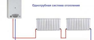
- The single-pipe scheme involves the movement of coolant sequentially from radiator to radiator with return to the boiler. This is the simplest scheme, but due to its low efficiency it is used in small one-story buildings.
Simplified axonometric two-pipe diagram Calculations when drawing up a heating scheme should take into account:
- Heat consumption in each room;
- Type and number of radiators;
- The number of risers, if any, as well as the total number of branches and circuits;
- Connection diagram for heating devices;
- Parameters of pipes and shut-off valves.
After completing the calculations of the heating system, they must be indicated on the diagram. The main purpose of an axonometric heating diagram is a graphical display of all parts and elements, but, in addition, the diagram must also display the technical characteristics of the heating equipment. The diagram must also include calculations for the heat supply to each room of the house, including utility rooms.
Hydraulic calculation of cold water supply
The hydraulic calculation of the cold water supply network begins after the constructive solution of the entire cold water supply system diagram, drawing an axonometric design diagram of the supply pipelines of the entire design building and quarter.
The purpose of the hydraulic calculation of internal cold water supply is to determine the estimated flow rates, pipe diameters and pressure losses in the calculated areas and throughout the system in such a way as to ensure uninterrupted water supply to all consumers in the building with the required pressure.
Hydraulic calculation is carried out in the following sequence:
A dictating point is selected taking into account the distance and height of the water fittings, as well as the amount of free pressure
for sanitary appliances.
The network is divided into design sections. Calculated
called the area where water flow is
permanent: pipeline sections between connection points of water fittings
to apartment wiring, apartment wiring to risers, risers to: highways. The breakdown into calculated sections is carried out against the direction of water movement, starting from the dictating point.
The number of devices served by the design area is determined. In this case, watering taps are not included in the calculation.
At each site the estimated water consumption is determined, l/s:
,
(4.4.1)
Where
–
maximum second consumption of cold water, l/s, related to one device. Its value is determined by the device whose flow rate is the largest. Consumption per device
determined in accordance with clause 3.2.
a
is
a value determined depending on the total number of devices N in the design area and the probability of their action
P c .
Its value is determined from the table. 2 adj. 4 .
Probability of device action P c
for different sections of the network is determined immediately for the entire building as a whole (since the ratio
U N
= const).
(4.4.2)
where U –
number of residents in the house;
N –
number of all water fittings;
– rate of cold water consumption by one consumer per hour of greatest water consumption, l/h (Appendix 3). (4.4.3)
– O
general rate of water consumption by the consumer at the hour of greatest water consumption, l/h (Appendix 3);
– rate of hot water consumption by one consumer per hour of greatest water consumption, l/h (Appendix 3).
Pipe diameters are selected from the table. for hydraulic calculation of water pipes based on calculated flow rates and permissible speeds. It should be borne in mind that the speed of water movement in the pipelines of internal water supply networks should not exceed 3 m/s. When selecting the internal diameters of cold water supply pipelines, you should focus on economical water speeds, which for pipes d 40 mm –
within 0.9...1.2 m/s.
Pressure loss, m, in sections of pipelines of cold water supply systems should be determined using the formula:
h =
i - l -( l + k l ),
(4.4.4)
where i –
specific pressure loss due to friction, mm/m;
/ –
length of the design section, m;
k–
coefficient taking into account pressure losses in local resistances.
In networks of utility and drinking water supply systems of residential buildings, k t =0.3 is assumed.
Along the main path from the dictating point to the city water supply, the amount of pressure loss is calculated.
It is convenient to perform hydraulic calculations in tabular form.
If there are risers on the axonometric diagram with different loads (number of devices), doubt may arise as to the correct choice of the dictating point. Therefore, to accurately find the dictating point, it is necessary to find the vanishing point (see Table 4.4.1.) of different risers (usually on the main line) and relative to it find the sum of pressure losses on one and the other branches, taking into account the difference in the geometric height of the installation of different devices (if dictating points adopted by different devices) and the required pressures necessary for their normal operation. Large losses determine the dictating riser and the location of the dictating point. Such a calculation is also necessary for drawing up a specification of materials and equipment for the entire house, since it is necessary to determine the diameters of all risers and sections of the main line. In this case, the table will look like:
();
Values are compared
And
. A riser is selected as the dictator, meaning
on which there is more.
Note:
It should be remembered that the section from the central heating point to the city water supply
(takeover) should be calculated at
And
.
Septic tanks
This sewerage scheme for a private house includes a device with simple mechanical cleaning.
A septic tank can consist of several containers. Heavy substances settle in the receiving part. The water then flows into the next section, where it is further purified. To increase the purification effect, many septic tanks are equipped with biofilters. The good thing about a septic tank is that it is easy to install, does not pollute the environment and does not emit unpleasant odors. Such a device is completely energy independent, but there are septic tanks with electric pumps.
Biological treatment system diagram
Biological treatment system diagram
This kind of autonomous sewerage scheme does not depend in any way on utility services. With all this, they have a fairly long service life. Such systems can be used to treat wastewater for country houses or cottages. They are also installed for entire villages. It is the most effective among all those used outside the city. Having such a wastewater treatment system at your disposal, you can be sure that it will serve faithfully for many years.
Storm drainage scheme
Storm drainage scheme
Currently, the most widespread type of storm sewer is based on the removal of wastewater through storm water inlets, which are located under drainpipes.
Installation algorithm
Installation of a two-pipe heating system, regardless of its characteristics, requires the use of the following tools, devices, materials and equipment
:
- tape measure, pencil/marker, building level, plumb line;
- electric drill;
- screwdriver;
- tool for pipeline installation (depending on the selected type of pipe);
- adjustable and gas wrenches;
- pipes (to choose from: metal-plastic, steel, copper, polypropylene);
- heating devices;
- air vents (manual for each battery, automatic for the entire circuit);
- expansion tank;
- boiler piping elements;
- drain valve and check valve for recharging the system, etc.
At the project preparation stage, it is necessary to perform a thermal calculation of the premises in order to determine the optimal power of heating devices. The type of radiators and pipes is also selected. Polypropylene is growing in popularity - such pipes do not corrode and do not overgrow, are suitable for hidden installation, are easy to install, and are affordable. The diameters of polypropylene pipes for a two-pipe system are determined depending on the thermal load and the length of the supply pipeline. The return line is mounted from pipes of the same section.
First steps
To get acquainted with the program, it was decided to purchase a basic set of one workstation. Specialists from the design department found out the features of the system and its ability to perform the tasks facing the designers and installers. At the same time, material was being compiled for assignment to CSoft Yaroslavl specialists, who had to finalize the reporting forms and program settings.
Of course, information about practical experience using PLANT-4D would be very useful, but at that time in magazines and on the Internet one could find data on increasing design speed, simplifying the designer’s work, comparative characteristics with other design systems - and very little about specific results , obtained in real conditions.
However, at the stage of familiarization with the program, the main problem was still different: it was necessary to decide what exactly, in addition to pipelines, should be depicted in the three-dimensional model of the project.
One of the most common mistakes when designing in PLANT-4D is the user’s subconscious desire to create a three-dimensional model of the project as close to reality as possible. The lion's share of designers' time is spent on detailed images of concrete and metal structures and existing pipelines. And it is not immediately clear that the graphic design of the project in PLANT-4D should be minimized, and the final refinement should be carried out when preparing the installation drawings.
Communication display order
The development of internal sewerage and water supply projects is carried out according to a single scheme. However, in the axonometric drawing, the water supply and drainage pipelines are depicted separately. The area located in the horizontal projection is transferred to the diagram in a similar way. Risers located in close proximity to a group of devices are displayed with large icons, and the pipeline is displayed vertically.
Detailed axonometric diagramSource vmasshtabe.ru
The riser, which is located at the maximum distance from the entrance to the house, is applied completely. Other elements are shown partially, indicating their brand. The vertical drawing of the riser allows you to depict the features of the shut-off valves installed on it.
The parts of the water supply system displayed vertically on the design drawing are drawn at an angle of 45°. According to the approved route, the water supply branch is mounted 30 cm above the floor level and laid with a slope of 0.002 in the direction of the main riser. The places where it connects to the water-type fittings are displayed vertically.
Schematic representation of elements and nodes
Axonometry of the water supply system provides that each individual element or node is displayed with individual markings and a serial number. A full description of the designations used for internal water supply and sewerage systems, as well as the direction of flow of liquids and other components, is given in GOST 21.205-93.
The most common elements of a domestic water supply system are shown in the image below.
Graphic designations of elements of internal water supply and sewerage systemsSource docs.cntd.ru
The direction of fluid flows and control elements are given below.
Graphic designations for the direction of fluid flows and their regulationSource docs.cntd.ru