Tichelman loop for two floors or more
Most often, such a heating system is installed in one-story buildings with a large area. It is in such houses that it works most effectively. However, sometimes such a system is assembled in two or three-story buildings. When performing wiring in such houses, you should adhere to a certain technology. According to Tichelman’s scheme, in this case it is not each floor individually that is connected, but the entire building as a whole. That is, an equal sum of the lengths of the return and supply pipelines is maintained for each radiator in the house.
The Tichelman loop on two floors is thus assembled according to a special scheme. Experts also believe that using only one circulation pump in this case is inappropriate. If there is such a possibility, the building should install one such device on each floor. Otherwise, if a single pump breaks down, the heating will be turned off in the entire house at once.
General Installation Tips
If your apartment is undergoing renovations, you can entrust the installation of the unit to professionals. Otherwise, if you are planning to perform this procedure yourself, you can use the tips below:
- If the renovation in the apartment was carried out a long time ago, before installation you should invite a specialist who will diagnose the wiring in the apartment.
- The wall serving as the installation site for the boiler must withstand a load twice the weight of the device.
- Access to the device must be free in case repairs are required.
- A sufficient analysis of the pipeline in the home is of no small importance. More precisely, the quality of pipes and risers, as well as the availability of outlets for directly connecting the unit, installing taps and other necessary manipulations. If the condition of the risers leaves much to be desired, it is necessary to first replace them and carry out repairs, otherwise the adequate operation of the water heater may be in question.
Installing a storage water heater in your own apartment is possible with your own hands. The most important thing here is compliance with safety precautions, as well as compliance with all installation rules.
Volume of water in the system
Of course, in order for the Tichelman loop heating system to work efficiently, before installing it, you should also calculate the required coolant flow. To determine this parameter, you must first calculate the heat loss of the building. This can be done using the formula G = S * 1 / Po * (Tv - Tn)k. Here Po is the heat transfer resistance, Tv and Tn are the air temperature outside and in the house, k is the reduction factor. The first and last indicators are determined from tables depending on the design features of the building. Actually, the coolant flow itself is calculated using the formula Q = G/(c*(T1-T2)), where:
- c is the specific heat capacity of water (4200),
- T1 is its return temperature,
- T2 - in the supply pipe.
The last two parameters are determined taking into account the nonlinearity of heat transfer from radiators. Ultimately, the difference between their values should be approximately 15-20 C.
Hydraulic calculation
This circuit requires calculating the power of the circulation pump depending on the length of the line.
An important component of the circuit is a hydraulic pump that creates pressure on the supply and vacuum on the return path. The calculation data demonstrate that the values of both parameters decrease as the distance from the pump increases in the direction of coolant movement. If you measure the data on a hundred-meter pipe, it turns out that when removed by 10 m, the supply pressure will be 90% of the nominal value, and the reverse vacuum will be 5%. With a range of 20 m, these parameters will be equal to 75% and 20%, respectively, and the drop on the radiator element in both cases will be 95%. At a distance of 50-60 m, the numbers shift to the middle (45 and 40, 40 and 45, respectively), and the decline on the radiator is 85%. With further distance from the pump, the proportions continue to change towards increasing vacuum; the pressure reduction at a distance of 70 m will be 90%, and at 80 m and more – 95%. Thus, in the middle part the pressure loss will be slightly greater than at the beginning and end. Proportionally changing indicators make it possible to maintain approximately equal radiator pressure drops.
With correct installation, no differences in the cross-section of the main pipe and the same height of the radiators, the system functions uninterruptedly. The power of the batteries involved will be equal to each other.
Opinion of country house owners about the system
According to most owners of country real estate, this scheme is indeed very effective - the Tichelman loop. This system has received simply excellent reviews. If it is properly designed and assembled, a very comfortable microclimate is established in the house. At the same time, the system equipment itself rarely breaks down and lasts a long time.
Not only the owners of residential buildings, but also the owners of dachas speak well of the Tichelman loop. The heating system in such buildings is often used irregularly during the cold season. If the wiring is done according to a dead-end circuit, when the boiler is turned on, the rooms are heated extremely unevenly. With a passing system, such problems, of course, do not arise. But assembling heating according to such a scheme is really more expensive than using a dead-end one.
Installation features when balancing is needed
As already mentioned, the Tichelman loop does not require adjustment of the amount of coolant passing through the radiators. But only when radiators of the same power are installed in the building. However, in large houses such a heating system assembly scheme is rarely used. For example, weak radiators are usually installed in the boiler room and other utility rooms, while more powerful models are installed in living rooms. Of course, all these batteries will need different ducts. If the coolant flow is calculated for weak radiators, it will not be enough for powerful ones. With reverse circuits, hydraulic noise will begin to appear in small batteries. To prevent this from happening, balancing valves are installed.
Associated heating circuit - device, use, how to do it
The associated heating pipeline wiring diagram is distinguished by the fact that it is considered self-regulating. If it is assembled correctly, then there is no need to adjust it after installation work. Each radiator in this system should have the same pressure difference between supply and return. Each heating device in a parallel circuit does not stop operating under similar hydraulic conditions.
How does a ride work?
The same pressure difference across the batteries appears due to the fact that the sum of the supply and return lengths is the same for everyone. This can be seen with your own eyes in the diagram. Take any battery from the system, and estimate the total length of the supply and discharge pipelines to the boiler.
Those. all radiators are in similar conditions automatically, and this is actually what other circuits achieve through fine tuning and sometimes cannot achieve. For example, it is not easy to set up a radial circuit, where each battery is connected by a long pair of pipes to one collector. The lengths of such pipelines are varied, the heating devices mutually influence each other, so the system has to be carefully configured.
Pipe diameters
It would be nice if the diameter of the main pipeline (both supply and return) were the same throughout the entire ring, except for connecting the last heating device. Where from the point of branching to the penultimate one, you can use a smaller diameter, because this will no longer be a main line, but a branch to the final heating device in the circuit. Those. the final cut of both feed and return can be with a small diameter.
Maintaining one significant diameter of the lines is necessary to ensure equal conditions for heating devices. Those. so that this “ride” would be a balanced system, where all batteries work stably under the same conditions.
If you start to “play” with savings and reduce the diameter of the line as the liquid moves (after all, less is required with each branch), then it’s very easy to make, so that the group of last heating devices will always be colder, i.e. The system will be difficult to configure.
Similarly, for a small house with 6 - 8 heating appliances, a pipe wire with a diameter of 26 mm is laid from the boiler (external for metal-plastic, for polypropylene and other materials - other values), then to the penultimate appliance - 16 mm. On the contrary, for the return line - from the first battery 16 mm, then from the second - 26 mm ring to the boiler.
However, this is only an example for a small system, and if, for example, the house is large, then the main diameter may need to be much larger so that the pipe wire does not make noise at the end sections, so that the speed in it does not increase by 0.7 m/s. You can determine the required diameter by a simple choice based on the connected power; an example of the calculation can be found on this resource.
Is a ride always necessary?
The associated heating system is more expensive when compared with a dead-end heating system, by 20 percent. The high monetary expense is associated with the use of large-diameter pipes, and namely their connectors - tees on the branches of heating devices and adapters to a smaller diameter to which heating devices are connected.
In a dead-end circuit, the pipe diameters will be smaller, since the entire power is divided into 2 or more arms at the exit from the boiler.
The hitch becomes especially large when it is not possible to run pipes in a ring around the perimeter of the building - from the boiler outlet to its inlet. Then the return line has to be returned in the same way as the supply line.
A complex loop emerges from three pipelines for highways of decent thickness. This must be avoided and the ride changed to the simplest dead-end scheme under certain circumstances.
A simple transition to a dead-end system occurs when the number of heating devices is reduced to 10 or less. Then it becomes possible to balance the heating devices at dead ends and the shoulders themselves without particularly increasing the pump force.
If there are 3, 4 or even 5 heating devices in an arm, there is no problem with balancing all the heating devices and arms in a dead-end heat supply circuit.
And if the same ten heating devices have to be divided along the shoulders as 6 and 4, then it is better to make a self-adjusting ride, just as with 6 heating devices and unequal dead ends, you will have to unnecessarily increase the power of the pump and excessively “squeeze” the batteries located closer to it.
Complications when developing a passing heating system and its configuration
If, as recommended, the diameter of the pipelines is the same, and the heating devices are located on the same multi-story level, and also, if there is no too significant difference in the power of the heating devices, then there cannot be any difficulties with the operation of the system.
More precisely, any problems like “the 3rd heating device does not heat” appear only due to violations of the installation process. For example, polypropylene was soldered with sagging and overlapping diameter inside.
However, if the factors mentioned above that are negative for the operation of the system are present, then differences in the operation of heating devices may appear.
- The one placed higher will take in more heat carrier.
- An overly powerful one will not be able to develop it to its maximum, and when the pump flow increases, very small batteries will begin to make noise due to the high speed.
- Those connected with a reduced pipeline diameter (the final one does not count) most likely will not develop power, since the pressure on them will be less.
In general, the ride is a stable scheme, but “gentle” - you shouldn’t break the rules for its creation, and everything will work as expected.
The only question that remains is the combination of very powerful heating devices with others, because if this is not solved, then the system will be... not applicable at all.
It may be that in the greenhouse we need one heating device of 5 kW, and in the toilet - 0.5 kW. By adjusting the pump and pipe lines for a 5-kilowatt unit, we will apply a pressure that is very high for it to the battery in the toilet and excessively increase the speed through it.
And the solution to the power conflict is the same as in the shoulder circuit - balancing valves. They should, at a minimum, sit on very low-power batteries in a ride, protecting them from high pressure.
However, if heating devices are controlled by local thermal heads, then a situation is possible when some turn off, and some that remain in operation begin to make noise due to the increased flow. Because of this, it is best to install balancing valves on all heating devices at once when developing an associated heating circuit for a home.
One of the main questions remains: is it possible to assemble an associated heating system for a house with your own hands? Of course you can. However, it is necessary to pay great attention to mastering the following issues as well.
Selecting the type of pipes and their diameter, choosing heating devices by power, piping the boiler, piping the heating device, a good selection of connectors, installation options, techniques and problems with the selected pipeline, training in the installation process. As a rule, even beginners in the plumbing business assembled good, efficient heating systems from innovative materials. It is possible that this will continue to happen.
The procedure for performing installation work
The work consists of the following operations:
- Boiler installation. The required minimum room height for its placement is 2.5 m, the permissible volume of the room is 8 cubic meters. m. The required power of the equipment is determined by calculation (examples are given in special reference publications). Approximately for heating 10 square meters. m requires a power of 1 kW.
- Hangment of radiator sections. The use of biometric products in private homes is recommended. After selecting the required number of radiators, their location is marked (usually under window openings) and secured using special brackets.
- Extension of the associated heating system line. It is optimal to use metal-plastic pipes that successfully withstand high temperatures, are durable and easy to install. The main pipelines (supply and return) are from 20 to 26 mm and 16 mm for connecting radiators.
- Installation of a circulation pump. Mounted on the return pipe near the boiler. The insertion is carried out through a bypass with 3 taps. It is necessary to install a special filter in front of the pump, which will significantly increase the service life of the device.
- Installation of an expansion tank and elements ensuring the safe operation of the equipment. For a heating system with a passing coolant movement, only membrane expansion tanks are selected. Safety group elements are supplied with the boiler.
To line doorways with a main line in utility rooms and utility rooms, it is allowed to install pipes directly above the door. In this place, to prevent air accumulation, automatic air vents must be installed. In residential areas, pipes can be laid under a door in the body of the floor or bypassing an obstacle using a third pipe.
Tichelman’s scheme for two-story houses provides for a certain technology. Pipe distribution is carried out with tying the entire building, and not each floor separately. It is recommended to install one circulation pump on each floor, maintaining equal lengths of return and supply pipelines for each radiator separately in accordance with the basic conditions of the associated two-pipe heating system. If you install one pump, which is quite acceptable, then if it fails, the heating system in the entire building will shut down.
Many experts consider it expedient to install a common riser on two floors with separate piping on each floor. This will make it possible to take into account the difference in heat loss on each floor with the selection of pipe diameters and the number of required sections in radiator batteries.
A separate associated heating circuit on the floors will greatly simplify the setup of the system and allow for optimal balancing of the heating of the entire building. But to obtain the desired effect, it is necessary to insert a balancing crane into the travel circuit for each of the two floors. The taps can be placed side by side directly next to the boiler.
Advantages and disadvantages
The passing system has more advantages than disadvantages.
Advantages of a system with associated water movement:
- The entire heating system warms up evenly, from the initial to the last radiator. Each room will be equally warm.
- There is no need to use expensive equipment and complex balancing.
- Possibility of installing heat regulators.
- Installation of the associated heating system is possible with your own hands; no special skills are required.
- The system has a long service life.
- High reliability and rare breakdowns.
- The system can be installed under the floor.
- The scheme is applicable for two-story houses.
- The system can operate by gravity.
Disadvantages of the system:
- Increased pipe consumption. Their length is longer than in traditional systems. Pipes require a large number of shut-off valves.
- The pipes have a larger cross-section compared to conventional schemes, which means they will cost more.
- With a complex configuration of premises, the use of the scheme becomes impossible due to restrictions on the contours (you cannot use right angles, different heights of pipes).
- If the house has a large area and several floors, such a system will cost a significant amount.
Installation of the Tichelman loop - useful tips
The layout of the rooms can complicate the assembly of such a system. For example, in any case, the highways will have to be pulled in the area of the door. In utility rooms, pipes may be laid above the opening. Indeed, in this case, special attention is usually not paid to the design of the room. In residential premises, the pipe is most often pulled under the door. To do this, you may need to perform a procedure such as punching a tie. If for some reason it is impossible to draw under the door, the return pipe returns to the same place where the supply came from. In this case, sections appear in the system where there are not two, but three pipes. This scheme is sometimes used in private homes. But assembling a heating system is expensive. Therefore, as mentioned above, in this case it is worth considering using a collector or dead-end circuit.
Tichelman heating feature
The idea of changing the operating principle of the “return” was substantiated in 1901 by the German engineer Albert Tichelman, in whose honor it received its name - the “Tichelman loop”. The second name is “reversible type return system”. Since the movement of the coolant in both circuits, supply and return, is carried out in one, parallel direction, a third name is often used - “scheme with parallel movement of thermal fluids”.
The essence of the idea is to have the same length of forward and return pipe sections connecting all radiator batteries with the boiler and pump, which creates the same hydraulic conditions in all heating devices. Circulation circuits of equal length create conditions for the hot coolant to travel the same path to the first and last radiator and receive the same thermal energy.
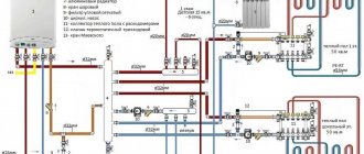
Tichelman loop diagram:
Factors of expediency of choice
Modern heating systems are presented in both the domestic and global construction industry markets in a wide variety. However, each of the proposed design solutions is advisable to apply in some specific cases. If we consider specifically the Tichelman loop system, its installation is a rational decision if:
- you have a large house, the organization of heating in which involves the installation of a large number of radiators;
- it is possible to lay pipes exclusively around the perimeter of the rooms;
- you are ready to spend a relatively large amount of money on organizing heating in your house.
Above is the traditional minimum list of conditions, according to which the choice in favor of a “ride” is rational and justified. Thus, if the operation of a circular pump is determined by the influence of balancing, and there is no need to lay a three-pipe system with large loops, it is the associated circuit that will function optimally in your home.
Valve setting - diagram with dead-end coolant movement
Volume of water in the system
Of course, in order for the Tichelman loop heating system to work efficiently, before installing it, you should also calculate the required coolant flow. To determine this parameter, you must first calculate the heat loss of the building. This can be done using the formula G = S * 1 / Po * (Tv - Tn)k. Here Po is the heat transfer resistance, Tv and Tn are the air temperature outside and in the house, k is the reduction factor. The first and last indicators are determined from tables depending on the design features of the building. Actually, the coolant flow itself is calculated using the formula Q = G/(c*(T1-T2)), where:
- c is the specific heat capacity of water (4200),
- T1 is its return temperature,
- T2 - in the supply pipe.
The last two parameters are determined taking into account the nonlinearity of heat transfer from radiators. Ultimately, the difference between their values should be approximately 15-20 C.
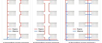
One-pipe and two-pipe system, open and closed loop
In addition to the type of wiring and location of the riser, variations in heating schemes are also divided into single-pipe and double-pipe. Single-pipe schemes are quite rare: they are used mainly when designing large premises. They are almost never found in residential buildings.
Single pipe heating system
In a single-pipe system, there is no supply and return pipeline; the coolant circulates through one single pipe, which is divided in half only mentally, considering the first part, which delivers water from the boiler, to be the supply, and the remaining half of the pipe to be the return. In a single-pipe system, hot water heated in the boiler rises, displaced by the cold return flow and enters the heating devices through the wiring, flowing from one to another, cooling and returning to the boiler for heating. Pumping circulation helps the fluid flow properly through the circuit.
The main problem of the circuit is the loss of heat by the coolant: the water reaches the last battery barely warm. This problem is solved by installing a pump and more radiators as they move away from the boiler. It helps to save heat by installing pipes in such a way that the first radiators into which still-not-cooled water from the heating element enters are batteries located in the coolest rooms, which require large energy costs for heating.
Two-pipe heating system
Although single-pipe systems are cheaper, those consisting of two pipelines are more popular. One delivers hot water from the boiler to the radiators, and the second collects the return flow of the cooled coolant and transports it back to the boiler. A two-pipe associated heating system, like a two-pipe dead-end system, is distinguished by the fact that water enters all heating radiators at the same temperature, and the problem of uneven heating does not arise. You can install a thermostat on each heating element and regulate the heat supply, which allows you to further save on heating the room. The installation pipes are thinner and look neater, fitting more neatly into the interior.
The weaknesses of a two-pipe heating system include the need to install shut-off valves and a Mayevsky tap on each heating element. Dead-end and associated circuits Heating circuits are also divided according to the principle of coolant movement in them. The associated heating system involves the movement of water in the supply and return lines in the same direction. A dead-end heating system assumes that the water in the return line moves in the opposite direction to the supply.
A dead-end circuit is characterized by unequal lengths of the contour rings of the heating radiators. The farther the radiator is located from the riser, the longer the path the water travels, moving from the boiler to the radiator and back. The further the heating element is from the heating element, the longer its circuit. Associated heating scheme is a scheme where the maximum identity of the resistance value of the material is realized, and the length of the heating pipes forming the contour rings is the same. The voltage in the circuits is also the same, which makes the distribution of resistance throughout the heating system uniform and facilitates its balancing. The disadvantage of an associated heating system with pump circulation is a more significant cost, because you need to buy a larger number of pipes. In conclusion, it is worth remembering all the positive aspects of pump circuits, because of which they are preferred:
- Such a system is launched in a short time
- The circuit with the pump operates without losses, providing effective heating of the room
- The pumps are durable and work without repair for a long time
- The pump makes no noise and consumes little electricity
WATCH THE VIDEO
Pumped circulation heating systems are very efficient. The advantages of heating systems with a pump outweigh the disadvantages.
Pros and cons of two-pipe wiring
For ease of perception, we have combined the advantages and disadvantages of all the above systems into one section. First, let's list the key positive points:
- The only advantage of gravity flow over other schemes is independence from electricity. Condition: you need to select a non-volatile boiler and install it without connecting to the house electrical network.
- The shoulder (dead-end) system is a worthy alternative to the Leningradka and other single-pipe distributions. The main advantages are versatility and simplicity, thanks to which a two-pipe heating circuit for a house of 100-200 m² can be easily installed with your own hands.
- The main advantages of the Tichelman loop are hydraulic balance and the ability to provide coolant to a large number of radiators.
- Manifold wiring is the best solution for hidden pipe laying and complete automation of heating operation.
The best way to hide pipes is to lay them under the floor screed
Note. The last 3 schemes can be easily combined with water underfloor heating circuits. Combining a gravity radiator network with heated floors is not always advisable - without electricity, forced circulation in heating circuits is impossible.
Let us briefly highlight the general advantages of the beam, associated and dead-end systems:
- small sections of distribution pipes;
- flexibility in terms of laying, that is, lines can run along different routes - in floors, along and inside walls, under ceilings;
- Various plastic or metal pipes are suitable for installation: polypropylene, cross-linked polyethylene, metal-plastic, copper and corrugated stainless steel;
- All 2-pipe networks lend themselves well to balancing and thermal regulation.
To hide the pipe connections, you need to cut grooves in the wall.
Let's note a minor advantage of gravity wiring - the ease of filling and removing air without the use of valves and taps (although with them it is easier to ventilate the system). Water is slowly supplied through the fitting at the lowest point, air is gradually forced out of the pipelines into an open-type expansion tank.
Now about the significant disadvantages:
- The scheme with natural water movement is cumbersome and expensive. You will need pipes with an internal diameter of 25...50 mm, installed with a large slope, ideally steel. Hidden installation is very difficult - most elements will be visible.
- No significant disadvantages were found in the installation and operation of dead-end branches. If the arms differ greatly in length and number of batteries, balance is restored through deep balancing.
- The Tichelman ring wiring routes always intersect doorways. You have to make bypass loops, where air can subsequently accumulate.
The house plan shows that the associated water system crosses 2 doorways - Beam-type wiring requires financial costs for equipment - manifolds with valves and rotameters, plus automation equipment. An alternative is to assemble a comb from polypropylene or bronze tees with your own hands.
Addition. To automatically regulate the heat transfer of batteries during gravity flow, you will need special radiator valves with an increased flow area.
Traditionally used heating schemes
- Single-pipe. The coolant circulates through one pipe without the use of pumps. On the main line, radiator batteries are connected in series; from the very last, the cooled medium (“return”) is returned to the boiler through a pipe. The system is simple to implement and economical due to the need for fewer pipes. But the parallel movement of flows leads to a gradual cooling of the water; as a result, the media arrives at the radiators located at the end of the series chain significantly cooled. This effect increases with increasing number of radiator sections. Therefore, in rooms located near the boiler it will be excessively hot, and in remote ones it will be cold. To increase heat transfer, the number of sections in the batteries is increased, different pipe diameters are installed, additional control valves are installed, and each radiator is equipped with bypasses.
- Two-pipe. Each radiator battery is connected in parallel to the direct supply of hot coolant and the “return” pipes. That is, each device is equipped with an individual return outlet. With the simultaneous discharge of cooled water into the common circuit, the coolant is returned to the boiler for heating. But at the same time, the heating of heating devices gradually decreases as they move away from the heat supply sources. The radiator, located first in the network, receives the hottest water and is the first to return the coolant to the “return” circuit, and the radiator located at the end receives the coolant last with a lower heating temperature and is also the last to return water to the return circuit. In practice, in the first device the circulation of hot water is the best, and in the last the worst. It is worth noting the increased price of such systems compared to single-pipe systems.
Both schemes are justified for small areas, but are ineffective for extended networks.
An improved two-pipe heating scheme is the Tichelman heating scheme. When choosing a specific system, the determining factors are the availability of financial capabilities and the ability to provide the heating system with equipment that has the optimal required characteristics.
Application of check valve
This mechanism belongs to the safe operation system. Its use on a pressure device is necessary.
When heated, the water in the boiler noticeably increases its volume, resulting in an increase in pressure in the vessel. The extreme manifestation of this process is its rupture. As a result, the room is filled with steam and hot water, which can cause significant harm to people.
When critical values are reached, the valve installed on the boiler opens the spring damper to discharge water, which is discharged through the fitting.
It must be securely fastened, since the discharge can be carried out with great pressure. After releasing excess water, the spring valve closes. The valve also has a lever for releasing water, which can be used manually.
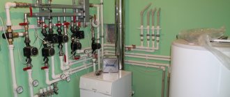
Installation stages
The heating system is assembled according to this scheme in the usual manner. That is:
The boiler is being installed. The height of the room where it will be installed should not be less than 2.5 m. In this case, the minimum allowable volume of the room is considered to be 8 m3. The boiler is usually selected based on the fact that 10 m2 of room requires 1 kW of power.
Radiators are being hung. The most popular type of this equipment is bimetallic batteries. Before hanging radiators, markings should be made. This heating equipment is usually mounted on special brackets.
The highways themselves are stretched. Most often, metal-plastic pipes are used to assemble heating systems, including associated heating systems. Their advantages include ease of installation, ability to withstand even very high temperatures and durability.
A circulation pump is installed. This device is usually mounted in close proximity to the boiler, on the return pipe. It needs to be inserted through a bypass with three taps. A filter must be installed in front of the circulation pump. This addition will significantly extend its service life.
An expansion tank and a safety group are installed. The first one is connected to the return line through one pipe. Of course, for the Tichelman system you need to choose a membrane expansion tank. The safety group usually comes with the boiler.
What are the advantages of this option?
When choosing between analogues that modern experts have developed for private homes, you need to understand what their distinctive advantages are. In the case of a hitchhiker, it would be fair to mention the following characteristics:
- Despite the fact that balancing measures still need to be carried out, their scale will be minimal, in contrast to similar types of work with other heating structures.
- Thanks to the design features of this type, the rooms are heated evenly, and the heat does not leave the house for a very long time.
- In conclusion, I would like to say that the associated circuit of a modern heating system, which is better known as the Tichelman loop, functions with maximum efficiency.
Within the framework of dead-end double-pipe type designs, radiators that are located closest to the heating equipment, as opposed to those located further away, tend to heat up to high temperatures. Naturally, such a situation requires the search for effective solutions. In this case, experts recommend installing balancing valves, with the help of which the amount of coolant flowing through the pipes near the heating unit is significantly reduced.
“Loop” is suitable for rooms with a simple layout
Unfortunately, even expensive balancing is not able to allow the user to run radiators at the power provided by the manufacturer. In addition, an additional monetary cost in organizing such a design is the mandatory purchase of a very expensive pump, the power parameters of which will ensure efficient movement of the coolant.
At the same time, the so-called Tichelman loop is known for the almost complete absence of such disadvantages. Thus, the batteries that are involved in its design function under average and equal conditions.
Horizontal and vertical risers
If the pipes connecting all heating devices to each other are located in a horizontal plane, this is a heating scheme with a horizontal riser. This approach is more economical, because Requires fewer pipes and lower installation costs. A horizontal heating riser - a main line supplying hot water, is more often found in one-story buildings with a large length, because With such a layout, it makes more sense to connect radiators in series one after another.
Heating system with horizontal piping
This design makes it possible to set separate temperature conditions for rooms and use heat meters. The disadvantage of the design is the occurrence of air locks in the pipes. To eliminate this problem, Mayevsky taps are installed on the batteries to release the excess air that has formed.
If a heating scheme with a pump involves connecting radiators to a common line, which are located on different floors, then this is a vertical riser heating system. With this installation scheme, radiators heating one apartment are powered from different risers, which makes it difficult to account for heat consumption in a single apartment. In a vertical heating circuit, the supply line runs under the ceiling of the top floor or through the attic, and all heating devices are connected in series to the main riser, which is located vertically and runs through all floors. Schemes of this type are used in multi-storey residential buildings. Each floor can be connected to the vertical riser separately; this is useful if the house is put into operation gradually. A vertical riser solves the problem of air accumulation in pipes, but installation of such a structure is more expensive.
An example of a vertical heating scheme for a private two-story house
The riser can pass directly through the apartment: penetrating the floor and ceiling in each room or be located outside the living quarters. In the second option, it suffers large heat losses, so it is “dressed” with a heat-insulating coating or placed in an insulated shaft. It is impossible to build heated floors in a circuit with a vertical riser; it is difficult to maintain the required air temperature in different rooms. It is warmer on the upper floors than on the lower ones, and the risers that are located further from the supply main are colder than those that are closer.
If heating devices are mounted directly to the distribution manifold, and each of them has a supply pipe and a return pipe, such a scheme is called a collector or radial. This approach is more expensive than previous options, but is used in installation because makes it possible to reduce the use of shaped elements and make the coolant speed the same in all circuits.
Lower and upper wiring diagram of autonomous circulation
Based on the type of wiring, heating circuits are divided into structures with lower and upper wiring. With lower wiring, the supply line is laid at the bottom of the coolant flow diagram, like the return pipe. Both lines are located below the heating devices. This design has high hydraulic stability and is convenient in that it allows the vertical pipes of the risers to be moved outside the rooms. With this arrangement, all circuit regulators (valves, locking mechanisms) are located in one room, usually a basement or technical floor.
Bottom type of heating system pipe routing
Bottom distribution of heating pipes saves heat, because they are not installed in attics or ceiling spaces. The disadvantage of this type of heating is the need to install air bleed valves on each radiator, as well as constant air locks.
With the upper type of wiring, the pipeline with the coolant passes in the upper part of the heating circuit. Typically it is located in the attic or in the space between the ceiling and roof. Return pipes are installed below heating radiators. An expansion tank is placed at the highest point of the circuit. It regulates the pressure inside the structure and eliminates the occurrence of air congestion. This type of heating cannot be installed in a house where there is no roof slope. The disadvantage of the upper distribution is the negative gravitational pressure in the vertical pipes. This interferes with the flow of water and reduces hydraulic stability. With overhead wiring, it is impossible to drain the risers centrally.
In addition to the lower and upper wiring, there is also a mixed one: the supply line runs from above, and the return pipeline passes through the lower part of the heating structure. This approach is reasonable if a multi-storey building has its own autonomous boiler located under the roof.
Pipeline materials
The modern market for building materials and the variety of heating equipment also dictate new solutions in the selection of materials for heating systems. Both the duration of operation of heating systems and the technical parameters of the purchased equipment (boilers, pumps, radiators) depend on the material from which the pipelines are made.
Steel pipelines of heating systems have been used for a long time in engineering systems. This is due to the fact that in Russia it will not be difficult to purchase such a pipe in the shortest possible time, and the price of systems made from steel pipes is the lowest. Steel pipelines are also resistant to high temperatures, temperature deformations are almost zero, and withstand hydraulic shocks well. But at the same time they have low corrosion resistance, so steel pipes are not recommended to be laid in building structures, that is, they must be installed in a hidden way. Thanks to all these advantages and disadvantages, the scope of application of steel pipe heating systems remains central heating and multi-storey budget housing construction.
Pipelines for heating systems made of copper are widely used in premium heating systems, since, despite all the advantages of copper, the price of such pipelines is the highest among analogues. Copper has the highest strength and heat resistance, withstanding pressures of about 200-400 bar and high temperatures up to 300°C. This allows the pipelines to be used both in central heating systems, where the coolant temperature can be about 150 °C, and in technological communications. The form of release of flexible copper pipelines of small diameters in coils allows for fairly quick and simple installation, laying pipes in building structures, having previously insulated them. Disadvantages of pipelines include the susceptibility of pipelines to electrochemical corrosion and the danger of destruction from stray currents. Therefore, it is strictly forbidden to use copper heating system pipes in combination with aluminum radiators.
Metal-plastic pipelines are used in independent heating systems where the coolant temperature does not exceed 95 °C. Due to their form factor (the pipe is supplied flexible in coils in sections of 25 or 50 meters), such pipelines are convenient to use for both underfloor heating and hidden installation. Due to low oxygen permeability, metal-plastic is not subject to corrosion. The disadvantages of metal-plastic pipes include the rather high cost of connecting fittings.
The most common option for installing heating system pipelines is the use of polypropylene pipes . This is the most inexpensive material, connected to each other using permanent solder fittings. But it should be remembered that for high-temperature environments, in particular for heating systems, only polypropylene pipes with a reinforced layer should be used. This type of pipe can withstand temperatures of no more than 95 °C, has a smooth inner surface, and, therefore, reduced hydraulic resistance. The disadvantages of polypropylene include low operating temperature, as well as the possibility of deformation and destruction of the chemical structure under the influence of sunlight. Therefore, polypropylene pipelines installed in an open manner must be covered with a layer of insulation.
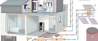
In the considered version of a residential building with an area of 70 m2, as an example, the heating system should be designed with forced circulation, made of polypropylene pipelines and with distribution manifolds installed on each floor. Despite the fact that the floor coverings are structurally laid wooden logs, the heating system pipelines can be installed in a hidden way by making small cuts in the logs (on top of the thermal insulation). In these recesses, pipelines can be laid with additional thermal insulation, and heating devices can be connected from the floor.
The procedure for performing installation work
The work consists of the following operations:
- Boiler installation. The required minimum room height for its placement is 2.5 m, the permissible volume of the room is 8 cubic meters. m. The required power of the equipment is determined by calculation (examples are given in special reference publications). Approximately for heating 10 square meters. m requires a power of 1 kW.
- Hangment of radiator sections. The use of biometric products in private homes is recommended. After selecting the required number of radiators, their location is marked (usually under window openings) and secured using special brackets.
- Extension of the associated heating system line. It is optimal to use metal-plastic pipes that successfully withstand high temperatures, are durable and easy to install. The main pipelines (supply and return) are from 20 to 26 mm and 16 mm for connecting radiators.
- Installation of a circulation pump. Mounted on the return pipe near the boiler. The insertion is carried out through a bypass with 3 taps. It is necessary to install a special filter in front of the pump, which will significantly increase the service life of the device.
- Installation of an expansion tank and elements ensuring the safe operation of the equipment. For a heating system with a passing coolant movement, only membrane expansion tanks are selected. Safety group elements are supplied with the boiler.
To line doorways with a main line in utility rooms and utility rooms, it is allowed to install pipes directly above the door. In this place, to prevent air accumulation, automatic air vents must be installed. In residential areas, pipes can be laid under a door in the body of the floor or bypassing an obstacle using a third pipe.
Tichelman’s scheme for two-story houses provides for a certain technology. Pipe distribution is carried out with tying the entire building, and not each floor separately. It is recommended to install one circulation pump on each floor, maintaining equal lengths of return and supply pipelines for each radiator separately in accordance with the basic conditions of the associated two-pipe heating system. If you install one pump, which is quite acceptable, then if it fails, the heating system in the entire building will shut down.
Many experts consider it expedient to install a common riser on two floors with separate piping on each floor. This will make it possible to take into account the difference in heat loss on each floor with the selection of pipe diameters and the number of required sections in radiator batteries.
A separate associated heating circuit on the floors will greatly simplify the setup of the system and allow for optimal balancing of the heating of the entire building. But to obtain the desired effect, it is necessary to insert a balancing crane into the travel circuit for each of the two floors. The taps can be placed side by side directly next to the boiler.
Which scheme is better to choose?
The selection of wiring is carried out taking into account many factors - the area and number of floors of a private house, the allocated budget, the presence of additional systems, the reliability of power supply, and so on. We will give a number of general recommendations for choosing:
- If you plan to assemble the heating yourself, it is better to opt for a two-pipe shoulder system. It forgives beginners many mistakes and will work despite the mistakes made.
- If you have high requirements for the interior of rooms, take the collector type of wiring as a basis. Hide the comb in the closet, and route the lines under the screed. In a two- or three-story mansion, it is advisable to install several combs - one per floor.
For radial wiring, it is advisable to place the collector in the center of the house - Frequent power outages leave no choice - you need to assemble a circuit with natural circulation (gravity flow).
- The Tichelman system is suitable for buildings with a large area and a large number of heating panels. It is not financially feasible to install a loop in small buildings.
- For a small country house or bathhouse, a dead-end wiring option with open piping is perfect.
Advice. Heating of a dacha for 2-4 small rooms can be organized using a single-pipe horizontal system with a lower distribution - “Leningradka”.
If the cottage is planned to be heated with radiators, heated floors and water heaters, it is worth adopting a dead-end or collector wiring option. The two indicated schemes can be easily combined with other heating equipment.
Tichelman heating scheme
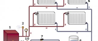
In country houses, autonomous heating is most common. This is due to the lack of a centralized or non-passage of main gas pipelines in most rural areas. For heating, small boilers are used, running on solid, liquid fuel, electrical energy and natural gas supplied in cylinders. The most commonly used heating system is water heating, which is characterized by its simplicity and reliability, compactness and hygiene. The main equipment for this method includes the following elements:
- hot water boiler;
- radiator batteries;
- water pipes;
- expansion tank;
- shut-off and control valves.
Trust modern technology
It's no secret that in the era of modern technology, people can let machines and software handle many routine tasks. Obviously, a newcomer to the construction industry is not able to fully carry out all the necessary calculations, as well as create a full-fledged heating project for the house from scratch. Fortunately, developers have already created special programs, the use of which significantly simplifies the design and calculation process. Typically, software for the construction industry is quite expensive.
Meanwhile, many companies offer free versions of programs that have such limited functionality that the user becomes familiar with the basic capabilities of the product. Actually, for designing heating in a country house, such a free version of a software product may be quite enough.
Diagram of water lines in the heating system
Tichelman heating feature
The idea of changing the operating principle of the “return” was substantiated in 1901 by the German engineer Albert Tichelman, in whose honor it received its name - the “Tichelman loop”. The second name is “reversible type return system”. Since the movement of the coolant in both circuits, supply and return, is carried out in one, parallel direction, a third name is often used - “scheme with parallel movement of thermal fluids”.
The essence of the idea is to have the same length of forward and return pipe sections connecting all radiator batteries with the boiler and pump, which creates the same hydraulic conditions in all heating devices. Circulation circuits of equal length create conditions for the hot coolant to travel the same path to the first and last radiator and receive the same thermal energy.
Tichelman loop diagram:
How to calculate pipe diameter
When installing dead-end and collector wiring in a country house with an area of up to 200 m², you can do without scrupulous calculations. Take the cross-section of mains and connections according to the recommendations:
- to supply coolant to radiators in a building of 100 square meters or less, a DN15 pipeline (outer size 20 mm) is sufficient;
- connections to batteries are made with a diameter of DN10 (external diameter 15-16 mm);
- in a two-story house of 200 square meters, the distribution riser is made with a diameter of DN20-25;
- if the number of radiators on a floor exceeds 5, divide the system into several branches extending from a Ø32 mm riser.
Advice. Above, in the example diagrams, the diameters of the mains and connections are quite accurately indicated. You can use this information when developing a home heating project.
The gravity and ring system is developed according to engineering calculations. If you want to determine the cross-section of the pipes yourself, first of all, calculate the heating load of each room, taking into account ventilation, then find out the required coolant flow using the formula:
- G – mass flow rate of heated water in the section of pipe feeding the radiators of a specific room (or group of rooms), kg/h;
- Q – the amount of heat required to heat a given room, W;
- Δt – calculated temperature difference between supply and return, take 20 °C.
Example. To warm the second floor to a temperature of +21 °C, 6000 W of thermal energy is required. The heating riser passing through the ceiling should bring 0.86 x 6000 / 20 = 258 kg/h of hot water from the boiler room.
Knowing the hourly coolant consumption, it is easy to calculate the cross-section of the supply pipeline using the formula:
- S – area of the required pipe cross-section, m²;
- V – hot water consumption by volume, m³/h;
- ʋ– coolant flow speed, m/s.
Reference. The speed of movement of the coolant in pressure systems with a circulation pump is taken from the range of 0.3…0.7 m/s. With gravity flow the flow is slower – 0.1…0.3 m/s.
Continuation of the example. The calculated flow rate of 258 kg/h is provided by the pump; we take the water speed to be 0.4 m/s. The cross-sectional area of the supply pipeline is 0.258 / (3600 x 0.4) = 0.00018 m². We recalculate the cross-section in diameter using the formula for the area of a circle, we get 0.02 m - pipe DN20 (outer - Ø25 mm).
Note that we neglected the difference in water densities at different temperatures and substituted the mass flow rate into the formula. The error is small, and is quite acceptable for handicraft calculations.