A huge number of electrical appliances used in everyday life and industry base their operation on determining the level of ambient temperature. The measuring element in them is a temperature sensor that is triggered when heated or cooled to a set level. They can be purchased in most stores; they are included with ovens, controllers and other devices, but it is much more interesting to make a thermostat with your own hands.
Example of a simple thermostat
Next, we will look at the principle of operation and options for making such a homemade product.
Mandatory thermostat composition
Each thermostat necessarily contains the following modules:
- Measuring unit (temperature sensor); logical block (comparison block); executive unit (electronic or electromechanical switch);
- The operation of the thermostat can be described as follows: the logical unit compares the temperature with the set one, and based on the comparison results, issues a command to the executive unit to turn on or off the heater (cooler).
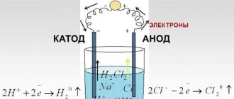
- Many temperature sensors are a measuring bridge (usually resistive). Such a bridge consists of four resistances, of which three resistors have a constant resistance, and one resistor changes resistance depending on temperature.
Having carefully studied the circuit for connecting resistors to form a logic (comparison) block, you can pay attention to the fact that the resistances of the resistors (all but one) are constant, while the resistance of one resistor varies depending on the temperature, this resistor serves as a sensor that measures the temperature environment, and the remaining resistors are elements of the unit for comparing the temperature with the set one.
When the sensor resistance changes, a potential will appear on one of the diagonals of the circuit, which can be used to control the thermostat actuator.
Usually, for the final comparison of the resistance of the temperature sensor with the resistance specified by the controller, a comparator microcircuit is used, which is the logical block of the thermostat.
- When a certain (set) temperature is reached, voltage appears at the comparator terminals, which can be used to further control the actuator, and it, in turn, will turn on or off the heating element (or cooler).
- Thus, various devices operate that require monitoring the temperature of an object. This could be an electric heating system, a water heater, an incubator or heated floor, a soldering station, or an engine cooling system. Control of furnaces or refrigeration equipment.
- As can be seen from this listing, temperature control devices can be used in a wide variety of areas.
Depending on how exactly the temperature is regulated, thermostats are usually distinguished according to the principle of their operation, namely, electromechanical and electronic; electronic devices can be distinguished as digital devices.
The work of the first two types consists of triggering the actuator when the object reaches a given temperature, and in digital devices, the signal from the sensor can be pre-processed, which is why such devices are most often used in PID control devices.
Aquarium heater
Less commonly, such a thermostat was used to maintain a set temperature in aquariums with tropical fish. This need arose due to the fact that the majority of thermal heaters produced for these purposes have a mechanical thermostat combined with a heating element in one housing. And therefore, they maintain their own temperature, and not the surrounding temperature, within specified limits. This works well only in rooms with a stable air temperature, within one or two degrees.
Installation features
- due to the inertia of water, the sensor and the heater must be spaced apart, but within direct visibility (without blocking by plants and decorative elements) from each other;
- due to the electrical conductivity of water, the sensor must be insulated either with means of good thermal conductivity or with a thin layer of conventional sealant;
- It is allowed to use both conventional aquarium heaters and adjustable ones with the temperature set to maximum.
You can find other areas of application for this simple-to-manufacture device. For example, for seedling greenhouses, drying cabinets, various thermal baths. What is your imagination enough for? Only if the load is susceptible to short circuiting is it necessary to add a 1 A fuse.
PS As mentioned above, this simple thermostat was used in incubators before, but now it has been replaced by microcontroller-controlled thermostats that can automatically lower the temperature during the incubation cycle. And the incubators themselves have acquired the function of regulating humidity and turning eggs.
Features of thermostat circuits
In thermostats, the actuator can be an electromechanical relay; in cases where the actuator is powered by alternating voltage, a thyristor can easily be used as an actuator.
- The undoubted advantage of using a thyristor over an electromagnetic relay is that it has no mechanical contacts, and this has a very positive effect on the service life of this element (especially when controlling powerful loads).
- The main advantage of the relay is the low voltage drop across its contacts when on. And this, in turn, significantly reduces its heating compared to a thyristor.
The comparator can be either a specialized microcircuit or a conventional operational amplifier microcircuit.
Concept of temperature controllers
Products in this category are used to solve various problems. Based on the appropriate temperature threshold setting, power is supplied (turned off):
- heating in the cellar;
- heating the soldering station;
- boiler circulation pump.
From the examples given, the basic requirements for accuracy that a suitable thermostat circuit must provide are clear. In some situations it is necessary to maintain a given level no lower than ±1C°. To monitor operating parameters, an operational indication is needed. Load capacity is essential.
The listed features explain the purpose of typical functional units:
- the temperature value is recorded with a specialized sensor (resistor, thermocouple);
- the readings are analyzed by a microcontroller or other device;
- the actuator signal is sent to an electronic (mechanical) switch.
For your information. In addition to the parts discussed, the thermal relay circuit may contain additional components to supply power to an electric heater or other powerful load.
Thermostat microcircuit
The modern level of integration of electronic devices makes it possible to design this device in a single microcircuit; such microcircuits can often be found in a wide variety of household and industrial devices.
However, when such a microcircuit fails, there is often simply nothing to replace it with. Therefore, in order to repair a thermostat, often, instead of such a microcircuit, a homemade thermostat assembled on separate elements is used.
Of course, such a device is much larger than a microcircuit, however, if the dimensions of the device allow, then the use of such a device can be completely justified.
Communities › Kulibin Club › Blog › Electrics: Temperature sensors, we make it ourselves.
Sometimes there is a need for temperature control of some process, be it a car or a national economy. There are many different thermal control schemes, but the sensors usually have an inconvenient design that does not allow for mounting in a controlled environment. Let's talk about sensors.
As a rule, semiconductor devices - thermistors - serve as sensors for measuring circuits:
The case may be different, but inside there will still be about the same droplet with leads.
The second common temperature sensor is the DS1820:
They are often sold as follows:
Inside is the same DS18B20 microcircuit with three pins, even without thermal paste.
Now let's try to implement these radio components into a car, for example, for digital display of coolant temperature or control of electric fans.
We will need a donor sensor - any suitable thread and cost. In my case, this is the Volga-UAZ sensor TM 106-10
:
We take a drill as a lathe and carefully clamp the sensor into the chuck. Using a metal hacksaw, we cut off the rolling. When the sensor falls apart into its component parts, use a drill to even out the edge of the sensor with a file. We receive a blank housing for introducing our radio component there.
Then you can go in two ways: 1. Pour molten solder into the body, drill a channel in this solder and insert a thermistor there. You can fill the housing cavity with thermal paste and stick the thermistor into it, but tin’s thermal conductivity is several orders of magnitude better than thermal paste, so thermal paste must of course be used, but it’s better to apply a thin layer of it.
The disadvantage of this method is the high inertia of the resulting sensor.
2. Do it the way I do it. Take a telescopic antenna from some old unnecessary device:
If you threw them away before, you did it in vain, because such antennas are a source of wonderful thin-walled brass tubes of different diameters:
We select the tube most suitable for the thermistor - it should be inserted as tightly as possible into the tube. We measure and again use the drill, cut off the piece of tube we need - it’s better to cut with a needle file. We take our blank body and drill its end according to the diameter of the tube. We tin the end of the body with tin, strip the tube down to brass and also tin it. We insert the tube into the case and solder them to each other, an 80W soldering iron is enough for your eyes. It should look something like this (the end is already sealed with a small piece of copper foil 1mm thick):
We check the resulting sensor housing for leaks. I do it not very technologically - using tongue suction
If everything is in order with the tightness, we proceed to the next stage: installing the thermistor and connector.
Again, we try everything on and cut off the leads of the thermistor so that when installed in the housing, the thermistor is at the end of the tube, or better yet, rests against the end:
The thermistor is now ready for installation. We put a little thermal paste inside the tube, coat the thermistor itself with a little thermal paste and insert it into the tube. After the thermistor has entered the tube under the connector, we place a little pre-prepared poxypol or epoxy plasticine. We press the connector into the polyester and remove the excess. When the Poxypol has completely hardened, you get this nice sensor ready for installation:
And this is how the sensor will stand at its workplace - the measuring part will be completely washed by the working environment:
Well, here’s a picture of a general check of the functionality of the electrical part:
Example of a thermostat
The thermostat can be made from parts that are not in short supply. They can be easily purchased in most cities.
The thermostat circuit is shown in the figure; it is a simple thermostat.
- To power the device, a source based on a step-down transformer is used as a diode bridge; low-power diodes suitable for reverse voltage are used, for example, 1N4007.
- An electrolytic capacitor is used as a smoothing filter, and an integrated voltage stabilizer is used in the power supply, with an output voltage of five volts.
- A medium power transistor with direct conduction is also used, for example, it could be a KT816A transistor. Also, the circuit uses the so-called controlled zener diode TL431.
- Constant resistance resistors with ratings 4.7; 160, 150 and 910 kilo Ohm. And a variable resistance of 150 kilo ohms. A 50 kilo ohm thermistor was used as a temperature sensor.
The characteristic of this resistance (positive or negative) depends on what load the thermostat will control (heater or refrigerator).
An LED is used as an indicator of the operation of the device, and an electromagnetic relay with an operating voltage of twelve volts (for example, a car) is used as a switching element.
A fixed switch for sufficient current and a housing with a volume sufficient to accommodate the device are also used. Also, for ease of installation, it is recommended to make a printed circuit board according to the diagram of the device being manufactured.
How to assemble a thermal relay yourself?
Heating control devices available for sale are quite reliable and do not cause any complaints. But at the same time, they cost money, and this does not suit those homeowners who have at least a little knowledge of electrical engineering or electronics. After all, understanding how such a thermal relay should function, you can assemble and connect it to the heat generator with your own hands.
Of course, not everyone can make a complex programmable device. In addition, to assemble such a model, it is necessary to purchase components, the same microcontroller, digital display and other parts. If you are new to this matter and have a superficial understanding of the issue, then you should start with some simple circuit, assemble it and put it into operation. Having achieved a positive result, you can move on to something more serious.
First, you need to have an idea of what elements a thermostat with temperature control should consist of. The answer to the question is given by the circuit diagram presented above, which reflects the operating algorithm of the device. According to the diagram, any thermostat must have an element that measures temperature and sends an electrical impulse to the processing unit. The latter’s task is to amplify or convert this signal in such a way that it serves as a command to the actuator - the relay. Next we will present 2 simple circuits and explain their operation in accordance with this algorithm, without resorting to specific terms.
Sequence of work
Having mounted the circuit in the chosen way, you should install the sensor in such a way that, during operation, it controls the temperature of the required object.
- The variable resistor should be installed in such a way that it can be easily accessed.
- After that, you need to put a scale of set temperatures that will be maintained by the thermostat.
After all this work has been completed, connect the power cord to the device (if you do this earlier, it will greatly interfere with operation).
After assembling and configuring the device, it is placed in the housing.
Advantages and disadvantages
Even a simple do-it-yourself thermostat has a lot of advantages and positive aspects. There is no need to talk about factory multifunctional devices at all.
Temperature regulators allow:
- Maintain a comfortable temperature.
- Save energy resources.
- Do not involve a person in the process.
- Follow the technological process, increasing quality.
The disadvantages include the high cost of factory models. Of course, this does not apply to homemade devices. But the production ones, which are required when working with liquid, gaseous, alkaline and other similar media, have a high cost. Especially if the device must have many functions and capabilities.
Photo of a homemade thermostat
Share with friends
Is it possible to make a temperature controller for a heating boiler with your own hands?
The design of any gas or electric boiler contains monitoring and control elements that monitor the temperature of the coolant at the outlet. But in older or inexpensive models, such components have a primitive design that only allows you to turn the heating on and off. Homeowners who want to optimize the operation of their heating system equip it with remote temperature controllers. Due to the high price of factory-made thermostats, they are made independently.
Connection options
- To the heated floor system;
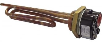
- To the heating element;
- To the heater.
Connecting a thermostat to a heated floor system
A standard underfloor heating thermostat is supplied with detailed instructions for connecting the device to the underfloor heating system. You can connect the TP yourself using the markings under the terminal blocks.
Underfloor heating mat
On the back of the regulator there are three pairs of terminal sockets for wires. The first pair is intended for connecting a two-core network cable. Socket “L” – phase, “N” – zero.
The second pair of sockets is intended for connection to the underfloor heating terminals – L1 and N1. The fifth and sixth terminals are used to connect to the temperature sensor.
Connecting the thermostat
Floor temperature regulators can be inserted into a socket box or mounted on the wall. The temperature sensor can be either built into the body of the device or installed at the end of an external cable.
In the first case, the air temperature inside the room is measured. In the second option, the sensor measures the degree of heating of the final floor covering.
Connecting the thermostat to the heating element
The thermostat must be connected to the electric heater through a magnetic starter. This is due to the fact that the power of the regulator is far from comparable to the power of heating elements.
A magnetic starter (MP) is needed when the thermostat controls several heating devices at once. The MP is cut into the phase wire in parallel with the thermostat. Adjustment of the operating modes of the heaters is carried out by a thermostat, the supply current passes through the MP. This makes it possible to use a three-phase power supply, which allows the operation of high-power heating elements.
Many TRs are equipped with electronic microprocessors, which additionally provide indicators of the level of humidity, pressure and time required to achieve the values of the specified parameters.
Connecting the thermostat to the heater
Thermostats can be mechanical or electronic. Recently, the second models have been actively displacing their mechanical counterparts. The use of modern electronics makes it possible to more effectively control the temperature in a given environment.
TRs for room heaters are built into heater housings or placed away from heating devices. The regulator, first of all, is connected to the electrical network, then through the control circuit it is connected directly to the temperature sensor.
Additional Information. In most cases, infrared heaters are connected to a thermostat via a magnetic starter. To connect the device correctly, you must strictly follow the instructions provided.
Features of how temperature control devices are connected depend on the type of heating devices. This can be a single-core or two-core connection of TP underfloor heating. The connection of a two-phase thermostat to three-phase current heating elements is carried out only through a magnetic starter. For water heating, the thermostat is embedded directly into the radiator. Each specific case has its own thermostat connection diagram.
general description
A room thermostat for a gas boiler consists of 2 metal strips that are used as an electrical switch contact in the heating system circuit.
The nominal contact drops with a sharp increase in temperature, due to this the heating function is turned off. When the microclimate changes, the necessary valves are automatically turned on and the boiler starts working again.
The body of this device is usually made of white plastic. LEDs are used to illuminate the display. The range for determining the temperature in the house for many devices is within 0…+45°C.
In addition to saving money, there are many more advantages
Typically, thermostats for a gas heating boiler are purchased to save money. Reducing the room temperature by even a few degrees reduces gas consumption by 5%. Due to the fact that the device reduces the number of cycles of heating equipment switching on, the owners’ costs for utilities are also reduced. At the same time, the equipment additionally ensures the safety of all boiler elements, which do not wear out so much.
Advantages of using a thermostat:
- setting a comfortable microclimate - you can select up to 7 modes;
- savings on gas payments (about 20%);
- increasing the operating time of all elements of the heating system, including the circulation pump;
- prevents severe dry air and overheating in the house;
- reduction in the number of boiler equipment starts.
Individually specified temperature settings for the thermostat are especially relevant for families with children, when it is necessary to maintain a comfortable microclimate at all times, as well as for those people who are especially sensitive to temperature changes.
In this video you will learn how a wireless thermostat works: