Heating : Artificial heating of the room during the cold season to compensate for heat losses and maintain a normal temperature with an average lack of supply of 50 hours/year. The internal heat supply systems of a building should be understood as heat supply systems for heating, water heaters, hot water supply systems, air heaters for air handling units, air conditioners, air heating units, air heat curtains, etc. (SP 60.13330.2012).
The main task of the heating system is to create comfortable conditions for visitors to the building. The goals of automation of heating systems are:
- Efficient and economical use of heat sources;
- Facilitating system management for the building maintenance service or the owner of a private home;
- Forecasting equipment maintenance;
- Load distribution and balancing on the building’s heating network;
- Preventing equipment failure;
- Reducing the influence of the “human factor”;
- Reduced utility costs.
A combination of automation systems for heating, ventilation and air conditioning systems form an automatic microclimate control system in a building.
Types of heating systems
Heating systems are classified according to the following criteria.
According to the type of heat exchange between the heater and the environment:
Convective heating . In this case, the transfer of thermal energy occurs along with the movement of volumes of hot and cold air: the warm air flow rushes upward, the cold air flows down. Due to the heat transfer mechanism, convective heating is impossible through any impenetrable barriers, incl. transparent.
Radiant heating . This is a type of heating in which heat is transferred by radiation. From the Sun to the Earth or from the heated surface to the observer.
Convective-radiant heating . Mixed mechanism. Most heating devices (radiators, convectors, heated floors and walls) transfer heat in this particular way; the optimal option is when there is an approximately equal (50/50) ratio of convective and radiant heat.
By type of coolant:
Water heating . Today the most common type of heating, which comes in the following types:
- Radiator heating, in which the following types of radiators can be used: cast iron, steel, aluminum, bimetallic, stone, ceramic, as well as convectors.
- Warm water floor. In this case, heating communications are laid under the floor covering.
- Baseboard heating. In this case, each section of the warm baseboard is a small convector with a casing, and installation is carried out like installing a regular radiator.
- Water infrared heating (“warm ceiling”). When installing such a system, a large infrared panel is attached to the ceiling, which is a heat source.
- Combined systems: include elements of the above heating systems.
Air heating . Air systems include systems in which the coolant is heated air. In supply ventilation, such systems can be local or distributed.
In local systems, heating and air supply are carried out directly in the heated room using heating and heating and ventilation devices.
In distributed systems, air is heated in an air heating unit and supplied to rooms through ducts.
In addition, there is fire-air heating, in which heat comes from stoves and fireplaces. With this type of heating, the coolant is either practically absent, or it is hot flue gases.
Heating systems without coolant.
- Electric heating systems. In such systems, electrical energy, converted into heat, heats the room rather than the coolant, for example, electric fireplaces, infrared electric panels, electric radiators or floors.
- Gas systems. In such systems, heat is generated by the combustion of a gas-air mixture. An example is gas fireplaces. picture of galley heating
Coordination of water temperature in the boiler and system
There are two options for how you can coordinate high-temperature coolants in the boiler and lower-temperature coolants in the heating system:
- In the first case, the efficiency of the boiler’s operation should be neglected and, at its outlet, the coolant should be supplied to the degree of heating that the system currently requires. This is what they do in small boiler houses. But in the end, it turns out that the coolant is not always supplied in accordance with the optimal temperature conditions according to the schedule (read: “Schedule of the heating season - beginning and end of the season”). Recently, more and more often in small boiler houses, a water heating regulator is installed at the outlet, taking into account the readings, which records the coolant temperature sensor.
- In the second case, the heating of water for transportation through networks at the exit from the boiler room is maximized. Then, in the immediate vicinity of consumers, the temperature of the coolant is automatically adjusted to the required values. This method is considered more progressive; it is used in many large heating networks, and since regulators and sensors have become cheaper, it is increasingly used in small heating supply facilities.
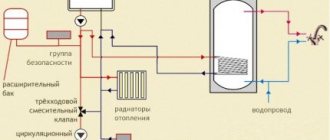
Heating system elements
Which elements can be used (and automated).
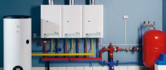
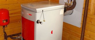
Boilers . The main element of any system, since this is where the process of fuel combustion occurs, after which the heat released during this process is transferred to the coolant (water or antifreeze).
According to the type of energy carrier, boilers are:
- gas;
- electrical;
- liquid fuel;
- solid fuel;
- combined;
- alternative, for example, solar collectors.
Depending on the number of coolant circulation circuits, boilers are:
- Single-circuit – intended for heating only;
- Multi-circuit – also used to heat water or turn on a heated floor system.
Burners . They are installed on gas boilers and can be fan-powered (with a supercharger) or atmospheric. Fan burners are noisier, but can operate at any incoming gas pressure.
Heating temperature chart . In apartment buildings, public and industrial buildings, boilers and burners are replaced by thermal power plants or thermal power plants. From the station, through the heating main systems, the heated steam enters the district heating district, and from it, in turn, to the building’s heating and heating system. From the heated coolant, in accordance with the temperature schedule, heat is transferred through ITP heat exchangers to the heating, ventilation and hot water circuits. At the outlet of their heat exchangers, the temperature of the coolant returning to the network must correspond to the temperature schedule.
Example of a temperature graph. Click to expand
| Outdoor air temperature Тнв, оС | Temperature of network water in the supply pipeline Т1,оС | Water temperature in the supply pipeline of the heating system Т3, оС | Water temperature after heating system T2, оС | |||
| 150 | 130 | 115 | 105 | 95 | ||
| 8 | 53,2 | 50,2 | 46,4 | 43,4 | 41,2 | 35,8 |
| 7 | 55,7 | 52,3 | 48,2 | 45,0 | 42,7 | 36,8 |
| 6 | 58,1 | 54,4 | 50,0 | 46,6 | 44,1 | 37,7 |
| 5 | 60,5 | 56,5 | 51,8 | 48,2 | 45,5 | 38,7 |
| 4 | 62,9 | 58,5 | 53,5 | 49,8 | 46,9 | 39,6 |
| 3 | 65,3 | 60,5 | 55,3 | 51,4 | 48,3 | 40,6 |
| 2 | 67,7 | 62,6 | 57,0 | 52,9 | 49,7 | 41,5 |
| 1 | 70,0 | 64,5 | 58,8 | 54,5 | 51,0 | 42,4 |
| 0 | 72,4 | 66,5 | 60,5 | 56,0 | 52,4 | 43,3 |
| -1 | 74,7 | 68,5 | 62,2 | 57,5 | 53,7 | 44,2 |
| -2 | 77,0 | 70,4 | 63,8 | 59,0 | 55,0 | 45,0 |
| -3 | 79,3 | 72,4 | 65,5 | 60,5 | 56,3 | 45,9 |
| -4 | 81,6 | 74,3 | 67,2 | 62,0 | 57,6 | 46,7 |
| -5 | 83,9 | 76,2 | 68,8 | 63,5 | 58,9 | 47,6 |
| -6 | 86,2 | 78,1 | 70,4 | 65,0 | 60,2 | 48,4 |
| -7 | 88,5 | 80,0 | 72,1 | 66,4 | 61,5 | 49,2 |
| -8 | 90,8 | 81,9 | 73,7 | 67,9 | 62,8 | 50,1 |
| -9 | 93,0 | 83,8 | 75,3 | 69,3 | 64,0 | 50,9 |
| -10 | 95,3 | 85,6 | 76,9 | 70,8 | 65,3 | 51,7 |
| -11 | 97,6 | 87,5 | 78,5 | 72,2 | 66,6 | 52,5 |
| -12 | 99,8 | 89,3 | 80,1 | 73,6 | 67,8 | 53,3 |
| -13 | 102,0 | 91,2 | 81,7 | 75,0 | 69,0 | 54,0 |
| -14 | 104,3 | 93,0 | 83,3 | 76,4 | 70,3 | 54,8 |
| -15 | 106,5 | 94,8 | 84,8 | 77,9 | 71,5 | 55,6 |
| -16 | 108,7 | 96,6 | 86,4 | 79,3 | 72,7 | 56,3 |
| -17 | 110,9 | 98,4 | 87,9 | 80,7 | 73,9 | 57,1 |
| -18 | 113,1 | 100,2 | 89,5 | 82,0 | 75,1 | 57,9 |
| -19 | 115,3 | 102,0 | 91,0 | 83,4 | 76,3 | 58,6 |
| -20 | 117,5 | 103,8 | 92,6 | 84,8 | 77,5 | 59,4 |
| -21 | 119,7 | 105,6 | 94,1 | 86,2 | 78,7 | 60,1 |
| -22 | 121,9 | 107,4 | 95,6 | 87,6 | 79,9 | 60,8 |
| -23 | 124,1 | 109,2 | 97,1 | 88,9 | 81,1 | 61,6 |
| -24 | 126,3 | 110,9 | 98,6 | 90,3 | 82,3 | 62,3 |
| -25 | 128,5 | 112,7 | 100,2 | 91,6 | 83,5 | 63,0 |
| -26 | 130,6 | 114,4 | 101,7 | 93,0 | 84,6 | 63,7 |
| -27 | 132,8 | 116,2 | 103,2 | 94,3 | 85,8 | 64,4 |
| -28 | 135,0 | 117,9 | 104,7 | 95,7 | 87,0 | 65,1 |
| -29 | 137,1 | 119,7 | 106,1 | 97,0 | 88,1 | 65,8 |
| -30 | 139,3 | 121,4 | 107,6 | 98,4 | 89,3 | 66,5 |
| -31 | 141,4 | 123,1 | 109,1 | 99,7 | 90,4 | 67,2 |
| -32 | 143,6 | 124,9 | 110,6 | 101,0 | 94,6 | 67,9 |
| -33 | 145,7 | 126,6 | 112,1 | 102,4 | 92,7 | 68,6 |
| -34 | 147,9 | 128,3 | 113,5 | 103,7 | 93,9 | 69,3 |
| -35 | 150,0 | 130,0 | 115,0 | 105,0 | 95,0 | 70,0 |
Read more about ITP automation.
Air valves . Serve to remove air from the system. Such valves are found in heating radiators and risers. Many are familiar with the Mayevsky manual valve.
Expansion tanks . As the temperature rises, the internal hydraulic pressure in a closed system filled with water increases, and to prevent an accident, excess water enters the expansion tank. If the system does not have a boiler, then an expansion tank is not required.
Circulation pumps . They are used for the movement of coolant in a system with forced circulation.
Pipeline system . They are used to move coolant through them; they are made of steel, copper and polymer.
Radiators, heated floors . Final heating devices. They are used for heating the room; they are made of steel, cast iron, aluminum and bimetallic.
sensors , flow meters, speed controllers and thermostats. All these tools are used to monitor system parameters, eliminate accidents, and control the system, manually or automatically.
Automatic temperature control of diesel water and oil
5.2 Automatic control of diesel water and oil temperature
When fuel burns in diesel cylinders, a large amount of heat is released, which heats the cylinder walls, pistons, covers, exhaust manifolds, etc. If heat were not removed from these parts, then the operation of the diesel engine would be impossible - the high temperature would not allow the supply of oil to the rubbing parts of the cylinder-piston group, would cause warping of parts, the appearance of cracks, etc. To remove heat from a diesel engine, water and oil are used as coolants. Water cools the diesel cylinders, cylinder covers and the rest of the exhaust tract. The oil cools the pistons and other rubbing parts. In modern diesel engines, in addition, it is necessary to cool the charge air, and in the hydraulic drive - its oil. By forcing water and oil to circulate between the heated parts of the diesel engine and cooling devices in a closed circuit, the required portion of the heat from the heated parts is removed by coolants and dissipated into the surrounding air. Experience shows that on modern diesel locomotives approximately 8...12% of the heat generated in the diesel cylinders is removed with cooling water, 6...10% with oil, and 4...6% with water cooling the charge air.
The process of heat dissipation into the environment is quite complex. This is due to the variable operating mode of the diesel engine, in which the amount of heat generated in the cylinders depends on the position of the controller and the load, as well as variable outside air temperatures, which can range from -50 °C to +40 °C. At the same time, to ensure the reliability and efficiency of diesel operation, the coolant temperature should not fluctuate within wide limits, but should be maintained at a certain level. In this regard, cooling devices must be able to regulate coolant temperatures.
The coolant is supplied to the tubular sections of the radiators of the cooling system, located at the front on the sides of the body in a special closed shaft. The coolant flows through a variety of externally finned sections of tubes from one collector to another. In this case, air supplied by the fan passes between the tubes of the sections along the entire front of their location. The air, passing between the tubes and their fins, picks up heat from the coolant and, heated, is thrown out of the shaft to the outside.
The shaft has louvers on top and sides that can be opened and closed using an electro-pneumatic drive or manually. The blinds protect the sections from mechanical damage, and opening and closing them allows you to change the flow of air supplied to the sections. When the fan is on and the blinds are open, air is drawn in from the atmosphere through the side blinds and pushed out through the top blinds.
Most series of diesel locomotives are equipped with automatic control of the opening and closing of the shutters to protect the radiator sections from hypothermia. The operating principle of an automatic device for protecting a diesel engine from hypothermia based on water temperature and oil temperature is the same.
Air is supplied to the cylinders 11, 7 of the side 12 and top 5 shutters from the air line of the locomotive through an electro-pneumatic valve 9, which turns on the thermal relay 8 depending on the temperature of the water (for the first circulation circuit) or oil (for the second circuit) at the outlet of the diesel engine.
The opening and closing of the blinds on modern diesel locomotives, as well as the turning on of the fan, are carried out automatically using eight single-limit sensors - temperature relays (thermal relays) of the RDK or KRD type, installed on the pipelines that drain water and oil from the diesel engine, and on the pipeline that supplies water to the air cooler. The thermal relays are adjusted to the following response limits: for water cooling the diesel engine: 76 °C - opening of the blinds; 84 °C - fan on; 96 °C - load dump; for diesel oil: 67 °C - opening of the blinds; 76 °C - fan on; 80°C - light alarm; for water cooling the charge air: 25 °C - opening of the blinds; 55 °C - turn on the fan.
Fan drives are divided into: mechanical from a diesel engine using cardan shafts, an angular gearbox and a friction clutch; hydromechanical from a diesel engine with the inclusion of a variable-fill hydrodynamic coupling in the mechanical system; hydrostatic without a mechanical connection between the fan shaft and the diesel shaft and electric with an individual AC motor for each fan. Diesel power consumption for fan drives accounts for a significant share - 5 ... 6%.
On the 2TE10V diesel locomotive, when the thermal relay is activated, the electrical signal is sent to the corresponding electro-pneumatic valve, which opens the access of compressed air to the corresponding pneumatic cylinder of the blind drive or the cooling device fan clutch.
The cooling device fan is driven from the rear distribution gearbox through cardan shafts, fan fluid couplings with an angular gearbox and a vertical cardan shaft. The fluid coupling is filled with oil through a fitting from the diesel system. When the fluid coupling is filled with oil, rotation from the drive shaft to the driven horizontal shaft is transmitted due to the pressure of the oil flow thrown from the blades of the rotating pump wheel onto the blades of the turbine wheel. When the bell cavity is completely filled with oil, the turbine wheel has a maximum rotation speed (2 ... 3 °/o less than the pump wheel rotation speed due to “sliding”). When the bell is partially filled with oil, the rotation speed of the turbine wheel will decrease depending on the degree of filling of the bell. By adjusting the degree of filling of the bell with oil, you can adjust the rotation speed of the fan, to which rotation is transmitted from a horizontal shaft through a bevel gearbox and a vertical cardan shaft.
The automatic water and oil temperature control system includes water and oil thermostats, a hydraulic piston drive of the variable-fill hydraulic coupling rack, microswitches, electro-pneumatic valves with pneumatic cylinders for driving the blinds. Temperature regulators for water (TRV) and oil (TRM) are located on both sides of the hydraulic piston drive (servomotor) of the fluid coupling filling rack. The thermostat rods, with the heads of the adjusting bolts screwed into the rods, rest against the horizontal pin connecting the cheeks of the lever 6 of the rigid feedback of the servomotor. When the temperature of the coolant (water or oil) rises above normal, the solid filler ceresin, located in the coil of the thermal cylinder 13 and washed by the coolant, expands and acts on the rubber plug 14 with the rod 15. The rod 15, moving in the sleeve 17, moves the lever along the slot of the sleeve 16, screwed into the rod, thereby releases lever 18, which, under the influence of a spring, closes the contacts of the microswitches of the water cooling circuit or the oil cooling circuit. Microswitches activate electro-pneumatic valves that control the opening of the side and top blinds. Each thermostat operates on the blinds of its own cooling system only. The upper blinds open when any microswitch is turned on, and close only when both microswitches are turned off.
Under certain conditions, opening the shutters may be sufficient to cool the water in the radiator sections. If the temperature of the controlled liquid begins to decrease, the volume of the solid filler of the thermal cylinders decreases and the rubber plug 14 is moved by the rod 15 under the action of the spring to its original position. The rod, with the lever 16 screwed into it, retracts the lever 18 and opens the contacts of the microswitch, thereby closing the blinds.
If opening the blinds fails to maintain the temperature at the required level and it continues to rise, the fan turns on and further temperature regulation is ensured by changing its rotation speed using a variable-fill fluid coupling. The hydraulic coupling operating mode is controlled as follows. Ceresin, heated in a thermal cylinder washed by liquid, moves rod 15 through plug 14, which, after being turned on by means of lever 18 of the blinds, moving further, rests the adjusting bolt against the pin of feedback lever 6, turning the lever clockwise. Together with lever 6, the spool rod 7 moves and moves the piston 10 to the right. Following the piston 10, the rack of the adjusting device moves, which meshes with the gear of the drive sleeve 21. The teeth cut at the second end of the sleeve 21 are meshed with the teeth of the gears 20. In this case, the fan rotation frequency increases. The process of increasing the fan frequency will continue until the temperature of the coolant stops increasing. In this case, the increase in the volume of ceresin stops and the thermostat rod 15 stops. Piston 10, moving to the right in the process of regulating the temperature of the liquid, moves spool 7 with lever 6. Thus, thanks to lever 6, the power piston always moves the spool towards the end of its movement, i.e. to the neutral position. Therefore, lever 6 is called a feedback lever.
When the temperature drops, the movement of the mechanism parts occurs in the opposite direction. The spool 7, under the action of the spring, moves to the right and the piston 10 moves to the left until the feedback lever 6 sets the spool to the overlap position. Therefore, the operation of the feedback lever 6 can be imagined as swinging relative to a fixed point, therefore, the stroke of the power piston will be proportional to the stroke of the thermostat rod.
For the entire range of adjustable rotation speed of the fluid coupling shaft (rack stroke 42 mm), approximately 5 mm of thermostat rod stroke is required, which is 5 °C temperature change (heating by 1 °C causes about 1 mm of thermostat rod stroke). From the above it is clear that when the operating mode of the cooling device changes, the temperature of the liquid will also change within 5 °C.
When switching to manual control, the temperature of the water and oil is regulated by turning the side and top blinds, as well as the fan, on and off. When you turn on the fan toggle switch on the control panel, compressed air is supplied to the pneumatic cylinder, which moves the piston to the left, compressing the spring, and through the pusher sets the spool to the extreme left position. This sets the maximum fan wheel speed for each driver controller position.
The hydrostatic drive of the fans of the cooling device of the TEP70 diesel locomotive consists of four hydraulic machines of the MH250/100 type, two of which operate in the hydraulic displacement pump mode and two in the engine mode. Unlike a hydrodynamic drive, which uses the kinetic energy of a fluid, a hydrostatic drive is based on the use of energy from the static pressure of a fluid. From the diesel shaft through a step-up gearbox (multiplier) 1, two hydraulic pumps 2, 3 are driven, pumping oil from the filter tank 10 and supplying it to hydraulic motors 7, where the energy of oil pressure is converted into mechanical energy of rotation of fans 8. In the nominal operating mode of the diesel engine, the hydraulic pumps provide maximum oil supply, forcing the hydraulic motors to rotate the fans at a maximum frequency of 1330 rpm. Changing the fan speed is achieved by bypassing the oil after the hydraulic pumps past the hydraulic motors. Changing the bypass is performed by thermostats 5, 6, which have temperature sensors washed with water or diesel oil. Under the influence of the ambient temperature, the volume of the sensor filler changes, causing the thermostat spool to move, which reduces or increases the oil bypass from the hydraulic pumps, bypassing the hydraulic motors.
To maintain normal operating oil temperature in the hydraulic drive system (60 ... 70 °C), oil cooling is provided in one oil-air section 9, installed in the cooling device shaft. Regulation of the rotation speed of the fan wheels of the cooling device is achieved by changing the oil pressure supplied to the hydraulic motors. The process of regulating the fan rotation speed is controlled by thermostats installed in the water and oil pipelines at the diesel outlet.
The command element of the thermostat is a thermal balloon (thermal sensor) 8 filled with ceresin, a crystalline substance with a high coefficient of volumetric expansion. The temperature sensor is covered on top with a rubber diaphragm 7. To enhance thermal conductivity, the temperature sensors are filled not with pure ceresin, but mixed with PACK aluminum powder in a weight ratio of 30% aluminum powder and 70% ceresin.
The temperature sensor works as follows. When the filler passes into the liquid phase, the central thickened part of the rubber diaphragm 7 moves upward, pushing out the rubber plug 6 along the channel of the sensor body. To increase the linear movement of the pusher of the working body associated with it) relative to the linear movement of the diaphragm that perceives the pressure of the filler, the plug is made with an area ratio lower and upper parts 1:6. Thus, the volumetric expansion of the filler in a thermal cylinder placed in the coolant in the design of the thermostat is converted into linear movement of the pusher 5, which in turn moves the spool 3, which controls the supply of fluid to the hydraulic motor. For temperature sensor 8, the pusher stroke is 6.6 mm at a water temperature of 69±2 °C and 10.5 mm at a water temperature of 80±2 °C and no more than 12 mm at a water temperature of 90±2 °C. Relatively small linear movements of the diaphragm and plug help reduce their wear.
Static unevenness of temperature control is allowed up to 12 °C and can be reduced by increasing the sensor gain. The magnitude of static temperature unevenness is also affected by the location of the temperature sensor. Therefore, they should be installed only in a “hot” coolant, i.e., the flow of water or oil at the outlet of the diesel engine.
Temperature regulators of the TEP70 diesel locomotive are installed on the water (one) and oil (two in series) pipelines at the diesel engine outlet. At a liquid temperature of 69±2 °C, washing the temperature sensor, the volume of the filler, having passed from the solid phase to the liquid, will begin to expand and through the diaphragm 7, plug 6 and pusher 5 will move the spool 3 upward. In this case, the working edge of the spool will gradually begin to overlap the annular slot. The oil will begin to flow to the hydraulic motor, which will rotate the fan wheel. As the size of the gap decreases, the amount of oil supplied to the hydraulic motor will increase, and its rotation speed will increase. The amount of oil in the drain will decrease. When the spool completely closes the gap, all the oil flow from the pump will flow to the hydraulic motor, the output shaft of which with the fan wheel will rotate at the maximum (design) speed. In this case, the temperature of the liquid (water or oil) washing the temperature sensor must be above 80±2 °C. As the temperature of the liquid decreases, the filler contracts, the gap will increase and some of the oil will begin to flow to the drain.
At temperatures below 69±1 °C, spring 2 returns the spool to the lower position, all the oil goes to drain without going to the hydraulic motors. The fans stop rotating and further cooling of the water and diesel oil stops. Thus, within the selected control interval, the thermostat smoothly changes the rotation speed of the hydraulic motor (fan).
At intermediate coolant temperatures, the drain gap is partially closed, and the fan wheel will operate at a frequency proportional to the amount of oil supplied to the hydraulic motor. Thus, stepless control of the hydraulic motor rotation speed is established using a thermostat.
The temperature of diesel water and oil is regulated not only by changing the fan speed, but also by opening or closing the shutters of the cooling devices, depending on the temperature of the water and oil.
The cooling device of the 2TE116 diesel locomotive is controlled both by an automatic system for regulating the temperature of water and diesel oil, and manually from the driver’s console.
Asynchronous electric motors of rectifier unit fans MV7, traction motors MV5 and MV6, as well as refrigerator fans MV1 ... MV4 receive power directly from terminals 1C1 ... 1C3 and 2C1 ... 2C3 of the stator windings of the traction generator through the contacts of three-pole circuit breakers AB7, AB5, AB6, AB1 ... AB4 and contactors K1 ... K4, respectively, both in diesel idle mode and in traction mode.
Automatic control of the refrigerator is activated by moving the toggle switch TX “Refrigerator Control” to the “Automatic” position when the automatic switch A6 “Refrigerator Control” is turned on and the contacts of the reversing mechanism of the controller B or H are closed. In this case, voltage is supplied to the contacts of the microswitches of temperature sensors-relays 0V, 1V, 2B, 0M, 1M, 2M automatic temperature control systems.
Sensor-relay 0M, when the oil temperature reaches 62 °C, supplies power from the TX toggle switch to the coil of the electro-pneumatic valve VP6 “Opening the left side blinds”. At a water temperature of 75 °C, the contacts of the 0V sensor-relay close, supplying power to the coil of the electro-pneumatic valve VP5 “Opening the right side blinds”.
When the oil temperature reaches 67 °C, temperature sensor-relay 1M supplies power to the contactor coil K4. Contactor K4 turns on the 4MV refrigeration chamber fan motor. At the same time, power is supplied to: - the coil of valve VP4 “Upper left blinds”; — to the valve coil VP6 “Opening the left side blinds.”
When the oil temperature reaches 72 °C, temperature sensor-relay 2M closes the circuit of the contactor coil K3 with its contact. At the same time, the coil of the electro-pneumatic valve VP3 “Upper right blinds” receives power. Contactor K3 with its main contacts turns on the motor-fan of the 3MV refrigerator shaft, and the VP3 valve opens its upper shutters.
In the same way, motor fans 1MV, 2MV of the refrigerating chamber are turned on and their upper blinds are opened; they are controlled by diesel water temperature sensors-relays 1B (operation temperature 79 °C), 2B (operation temperature 83 °C).
The TX “Refrigerator Control” toggle switch is moved to the “Manual” position when switching to manual control of the refrigerator. The temperature of water and diesel oil is regulated by turning on the corresponding toggle switches T1, T2 (for water) and T3, T4 (for oil) on the control panel.
Get text
What and how to automate? Basic principles
Depending on the type of coolant heating system, the control and parameters controlled by the automation system will differ.
In general, the operator sets the desired temperature in the room, via the control panel or via a PC, via a remote control in a separate room, etc.
The heating automation system, based on data on the air temperature in the building, the outside air temperature, the time of day, and the presence of people in the room, selects an operating mode and transmits control signals to actuators, which may differ:
A) To control the electric heating system, devices are used that control the power of the electric current: bimetallic thermostats operating on the “on/off” principle, or thyristor voltage regulators, with the help of which, when the voltage decreases, the power consumption of the device is also reduced. As an example, we can recall an electric convector, the user sets the required temperature, and the thermostat maintains the temperature by turning on and off the power supply to the device.
B) To control a heating system with a coolant circuit, devices are used that regulate the temperature and flow of the coolant. At the same time, adjusting the temperature of the coolant is possible only in autonomous systems with boilers and heaters, for example, in private houses; for centralized heating systems, the temperature of the incoming and outgoing coolant flows is given by the graphs:
- from large thermal power plants: 150/70°C, 130/70°C or 105/70°C;
- from boiler houses and small thermal power plants: 105/70°C or 95/70°C.
Thus, at large facilities, room temperature control can only be carried out using devices that change the coolant flow in the heating network and maintain it at a given level, so as not to go beyond the temperature schedule.
Trial and error method
This method relies entirely on the individual intuitive experience of the installer and consists of closing and opening control valves in the hope of adjusting the heating system.
The result of the adjustment is most often determined by the temperature of the heating devices - it should be the same.
Advantages of the method:
- simplicity and low financial costs, no additional technical equipment required;
- Anyone can use this method; no special training is required;
- Small systems can be configured satisfactorily.
Minuses:
- inaccuracy of adjustment;
- It’s difficult to set up large systems; it requires a lot of time and willpower (and in the case of weak intuition and little experience, you’ll have to run around a lot).
This method is characterized by folk wisdom: “If it doesn’t come through the head, then it comes through the arms and legs.”
Main components of the heating automation system
- temperature (indoor, outdoor, coolant) and pressure sensors, which provide a constant supply of information about the state of the heating system;
- thermostats (setters, thermostats) that regulate the coolant supply;
- drives and actuators (valves, circulation and make-up pumps, frequency regulators) perform the function of regulatory and safety mechanisms that ensure reliable and trouble-free operation of the system.
- automation panels (controllers, expansion modules) that control the heating system
Methods for adjusting the temperature of heated floors
More than one article on our website is devoted to adjusting the heating temperature of underfloor heating. In short, there are the following options:
- Adjustment of the temperature of the heated floor in conjunction with an overhead temperature sensor on the manifold and a circulation pump. The sensor feels the temperature on the collector (initially too high) and as soon as it gets the desired temperature, turns off the power to the pump.
- Installation of a supply pump paired with a three-way valve. Thanks to the three-way valve, the heated floor is mixed to the desired temperature.
- Installation of heated floors using a mixing module. The mixing module contains everything necessary to regulate the temperature of the underfloor heating system.
- Similar to a radiator. Installation of servo drives on the manifold in conjunction with thermostats.
Read more in the article 4 ways to adjust the temperature of a heated floor
As a bonus. Here's a relatively inexpensive and accurate way to regulate the temperature of a heated floor:
Sensors
The sensors are designed to monitor pressure and temperature indoors, outdoors and coolant in the pipelines of the heating system.
Temperature sensors are:
Submersible . Designed to take readings about water heating in pipes. Their installation is carried out in certain areas of the system. These sensors are bimetallic and alcohol
Remote . This type of sensor is installed outside the heating system. Recently, wireless models have become popular, which transmit information using auxiliary electronics, which makes it possible to install them almost anywhere - in a separate room or outdoors.
Pressure sensors can be mechanical - pressure switches (mechanical measurement of pressure difference and electrical conversion) and analog pressure sensors (conversion of pressure directly into an electrical signal, for example, using piezo elements).
Optimal temperature for the boiler room
To ensure effective heat transfer, heating boilers must have a higher temperature, since the more heat a certain volume of water can transfer, the better the degree of heating. Therefore, at the exit from the heat generator, they try to bring the temperature of the liquid closer to the maximum permissible values.
In addition, the minimum heating of water or other coolant in the boiler cannot be lowered below the dew point (usually this parameter is 60-70 degrees, but it largely depends on the technical features of the unit model and the type of fuel). Otherwise, when the heat generator burns, condensation appears, which, in combination with aggressive substances contained in the flue gases, leads to increased wear of the device.
Thermostats
Thermostats are a control element of the system and can be mechanical or electronic.
Mechanical thermostats consist of a thermal head (sensing element) and a valve. The working fluid of the sensitive element is a liquid, gas or elastic element that changes its shape depending on temperature. When the air temperature in a heated room changes, the volume of the working fluid changes. The sensing element reacts to this and moves the regulator valve stem. This changes the flow area in the channel.
Electronic thermostats (ET) . This is an automatic device consisting of several devices that ensure the maintenance of a given temperature in thermal installations. In the heating system, they automatically control the operating modes of equipment and actuators (boilers, mixers, pumps, valves, etc.), and the result of their operation is the creation of a temperature regime specified by the user in the room.
Digital thermostats come with “open” and “closed logic”. Closed logic implies strict control algorithms and a certain set of external devices connected to the system (sensors, actuators). Only limited parameters can be changed; the user cannot program control algorithms.
In large systems, thermostats with open logic are used - these are freely programmable controllers with a wide range of settings and functions. They can be integrated into a centralized building management system. Mounted in automation panels. Installation and configuration of such thermostats requires certain qualifications.
Principle of operation
The mechanical control device in the weather control system СART is a three-way valve that mixes the heated water supplied from the heat source with the coolant from the return pipeline. The mixing ratio is set by an electronic controller depending on the data received from temperature sensors and the specified operating mode.
The design of the system allows its owner to independently adjust temperature parameters depending on the time of day and day of the week. Thus, the design of weather control makes it possible to ensure that the temperature of the coolant is constantly consistent with the conditions for creating comfortable conditions in the room.
Actuator drives
Valve drives can be threshold (two or three position) and analog, with the possibility of smooth regulation.
The most famous and common method of regulation in a pumping system is regulation by a damper when the engine is running at full speed, and pressure regulation in the system is carried out using shut-off valves (gate valves, taps, bends, ball valves, etc.). The operation of the pump is ensured by a constant supply of energy to it from an electric motor, and it is controlled by a pressure control device.
Regulating the throttle can be compared to driving a car: when the gas pedal is pressed all the way, the speed of movement is regulated by the brake pedal.
A more economical way to control coolant flow is to use frequency converters to regulate the rotation speed of heating system pump motors.
With this method of regulation, up to 50% savings in energy consumption are achieved, and if we take into account that during its service life the engine consumes electricity in an amount that far exceeds its cost, then this indicator turns out to be extremely relevant. For example, an 11 kW engine operating for 8 hours a day throughout the year will consume electricity in the amount of about 145 thousand rubles. (at a tariff of 4.5 rubles/kWh).
Automation boards
Heating automation panels are used to control the heating system. They are used to control circulation pumps, control valves with pulse or analogue control, gate valves and solenoid make-up valves.
The automation panel can be equipped with temperature, pressure and differential pressure sensors, or the manufacturer indicates a list of compatible equipment.
Functions implemented in automation panels:
- Regulation of supply and return coolant temperatures for heating systems;
- Maintaining the specified value of the selected parameter, regulating the parameter according to the network diagram;
- Enabling energy saving modes at night, on holidays and weekends, controlling circulation pumps, lowering the temperature of hot water in the circulation circuit;
- Protection against valve sticking (periodic run);
- Control of the operation of the main and backup pumps with the organization of their alternating operation, automatic transfer switch and protection against “dry running”;
- Automatic restart of pumps in case of power failure;
- Other functions.
When connecting sensors to a heating automation panel, take into account the type of signal transmitted by the converter - analog, discrete or threshold - open/closed. Expansion modules that control device drives are selected based on the same principles, taking into account the type of control signal and control protocol.
Control units
CONTROL VALVES TYPE ASSEMBLY
Control valve piping units are designed for automatic control systems for heat/cold supply of central air conditioners and supply ventilation units with heat/cooling water. Automatic control of air temperature is carried out by changing the temperature of the water supplied to the heat exchanger (air heater or air cooler), while maintaining a constant flow rate.
A standard range of piping has been developed in twelve sizes, differing in the nominal diameter of the control valve (from 15 to 80 mm) and the diameter of the heating system (from 15 to 100 mm).
Diagram and composition of the harness
The diagram and composition of the harness are shown in the figure. According to the customer's instructions, the strapping unit is made in horizontal or vertical design. The horizontal version has two connection options: right and left. As specified, a differential pressure regulator is installed.
The primary circuit includes pipelines from the heat supply source to the control unit and partially the pipelines and equipment of the control unit.
The secondary circuit includes pipelines from the control unit to the air heater (air cooler) and partially the pipelines and equipment of the control unit.
Operating conditions for strapping units:
- ambient temperature - 5-40°C;
- maximum coolant temperature at the inlet (from the IHP) - 150°C;
- maximum coolant temperature at the outlet (to the heater) - 100°C;
- maximum pressure - 1 MPa.
Basic elements of strapping knots
1. Circulation pump from Grundfos. Circulation pumps with a wet rotor are used.
2. Three-way seat-type control valve from Danfoss.
3. Actuators of three-way valves are electric gear drives. The valve's electric drive is controlled by a pulse, current (0 - 20 mA) signal or voltage (0 - 10 V).
4. Balancing fittings from Herz.
Main technical characteristics:
| Supply voltage | Current frequency | Rod stroke | Operating ambient temperature | Protection class |
| 24 V or 230 V; (+10%, -15%) | 50/60 Hz | 15, 20, 30, 40 mm (depending on valve diameter); | from 0 to +55°С | IP 54 |
Note:
- in the manufacture of components, components other than those indicated in the table may be used;
- If necessary, it is recommended to install a direct-acting differential pressure regulator.
It is recommended to install a coolant differential pressure regulator in the supply and return pipelines in the following cases:
- if the valve authority is less than 0.35;
- when the pressure drop across the valve is more than 200 kPa;
- when the pressure drop across the valve exceeds the pressure drop at which cavitation occurs.
For the optimal selection of control valve trim components, we have developed a selection program.
Program for calculation and selection of control units
The calculation and selection program is designed to determine the main parameters of the units for qualitative control of water air heaters and quantitative control of water air coolers.
Using this program, it is possible to calculate and select the main elements of the control unit based on the given values of heat flow and coolant (coolant) temperatures, as well as hydraulic mode data.
For calculation, select: 1. System:
- heat supply;
- refrigeration supply.
2. One of the heat supply source options:
- centralized - from the heating network;
- autonomous - local boiler house or independent connection of the heat supply system of air heaters to the central heating network.
Heating automation system design
The equipment and algorithms of the heating system automation project are carried out using the technology of the heating system developers. A typical project composition may be as follows:
- Common data;
- Structural diagrams, if necessary;
- System programming task;
- Functional automation diagrams for each of the subsystems - automation panels will be assembled according to them;
- Communication diagrams of automation system controllers;
- Connection diagrams with related automation systems;
- Diagrams of external connections for automation panels (in fact, this is a table of connections);
- Schematic electrical diagrams of automation panels, pump motors, valve controls;
- Schematic diagrams of power supply for automation panels;
- Layout of equipment and wiring of automation systems;
- Cable magazines;
- Installation diagrams;
- Specification of equipment and wiring.
System operating modes. Work in the building automation and dispatch system
Heating control systems can operate in the following modes.
Manual mode . In this case, setting operating modes, switching equipment from primary to backup and many other functions are carried out manually by the operator, and it does not matter whether he presses buttons on the automation panel or on the PC, this is manual mode.
Automatic offline mode . In this case, the operator turns the system on and off; subsequently, the system operates according to a given algorithm and transmits information about its state to the operator or dispatcher.
Automatic as part of an automated building management system. In this mode, the operation of the heating system is synchronized with other life support systems of the building; the operator or dispatcher does not take part in the control.
Automation of heating of a private house
Heating system installations for private houses are equipped with automation systems; as a rule, they are closed and come with a set of all necessary sensors and regulators.
The main tasks that automation of heating of a private house solves are:
- control of heating boiler operation;
- providing comfortable living conditions;
- saving fuel and operating equipment in optimal mode.
Setting up an automation system for home heating systems is often quite simple and is carried out either by the owner of the building or by the organization that installed the system itself.
Setup
Setup is preparation for use. Synonyms for the word adjustment: adjustment, debugging, repair, adjustment, checking, correction. Antonyms: disassembly, breakdown, accident.
So, the heating system is filled and pressurized. It's time to start adjusting, thermal testing and putting it into operation. Before adjustment, the following work must be completed:
- heating system installed;
- its compliance with the project was checked;
- the system is flushed and filled with water;
- commissioning of the main equipment was carried out.
During the commissioning process the following must be done:
- turn on the main equipment;
- listen carefully and take a closer look at what is happening around - extraneous noises, vibrations, the presence of water leaks, the smell of burning, bright flashes and much more should alert you.
Maybe it's time to run away from here? Or is it necessary to open the closed valve at the pump? Or maybe after pressing the “On” button nothing changed because they forgot to plug the plug into the socket or did not open the gas supply valve to the boiler?
Situations are different, and in order to be prepared for anything, you first need to understand and imagine the structure of the heating system, which is being adjusted.
Necessary:
- carefully monitor the readings of all available instrumentation;
- set up and adjust various circuits of the heating system;
- do not forget to sign the acceptance certificate.
In general, the setup process can be divided into several stages, each of which is responsible for setting up and adjusting a certain group of system nodes:
- adjustment of a boiler unit or heating point;
- hydraulic and thermal adjustment of the heating system.