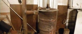
Autumn time - the cauldrons are charming! Another installation of the Kupper boiler. It seems that what to say about this - everything has been said. But no, every installation of a stove and chimney has at least one, but its own, special nuance. So in this case it could not have happened without it.
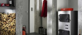
Universal Heating and Cooking Boiler “Kupper” OVK-10, manufactured by Teplodar, Novosibirsk. The boiler is designed to heat a room up to 100 square meters, with a ceiling height of 2.7-2.8 meters. A boiler with a hob (removable cast iron rings) for heating and cooking. Type of fuel: firewood, coal, peat, briquettes, pellets, electricity. An electric heating element of 6 kW, 3 turns of 2 kW each, is supplied with the boiler. The boiler is universal both in terms of the type of fuel and the side of the heating system supply; the system can be supplied both on the right and on the left. The chimney outlet is at the rear of the boiler, diameter 115 mm. The firebox is made of boiler steel, 3 mm thick. It can be purchased separately for the boiler.
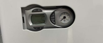
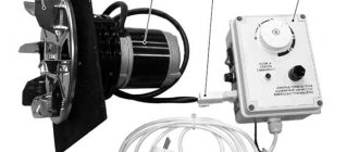
Control panel for the heating element unit PU EVT-I1 (6 kW) for an electric heating element and switch the operation on electricity to automatic mode. The remote control has two sensors: one is a coolant temperature sensor and is installed on a metal pipe at the entrance to the boiler (on the return side), the other is an air temperature sensor and is placed in the living room or in the boiler room, if the temperature there is the same as in the house. The control panel will allow you to automatically turn on/off the heating element based on the parameters specified in the settings
By the way, here’s another interesting idea: you can install a GSM module in the electrical circuit of the heating element-remote-socket. This will allow you to turn on the electric heating element remotely using SMS from your phone. Watch the video made by our partner.
Residential bathhouse, dimensions 6x6, frame, well insulated. The bathhouse is very beautiful! This boiler is an excellent solution for heating small rooms, such as the bathhouse of a customer who contacted our online store to consult on the boiler, select a chimney and buy a “Kupper” boiler. At the same time, it was necessary to install a boiler and install a chimney.
The customer decided to install the heating system on his own. In any case, we warned about the mandatory installation of a safety group on the boiler (blasting valve, air valve and expansion membrane tank) and problematic issues in small-volume systems, i.e. responsible regulation of the intensity of fuel combustion so that the boiler does not boil. The buyer himself knew this very well when preparing to build his bathhouse.
Having arrived at the site, the installers inspected the installation site of the boiler and the front of the installation work: where we would place the boiler (platform) and how the chimney would go, bypass the roof slope with sandwich elbows or cut it. In matters of installation, the customer completely relied on the professionalism of the installers - “the main thing is to do it like your own.”
Many buyers believe that the boiler can simply be placed on a wooden floor, laying just a metal sheet or a heat-resistant plate under it. This is a deep misconception. Do not neglect the additional thermal protection of the boiler stand.
The platform for the boiler was made as follows: using foil-coated basalt cardboard, Flamma heat-resistant board, brick, decorating the resulting structure with the remains of the heat-resistant board.
The location of the site was made in such a way that the heating system could be installed on the left, while there was space on the right for installing a heating element and under the bathroom. In other words, before installation it is worth considering all the nuances of the subsequent operation and maintenance of the boiler room, taking into account the observance of distances for fire safety purposes.
They placed another boiler on top of the boiler in order to mark the chimney exit through the wall to the street and determine the installation of the passage unit.
Next, we used an electric jigsaw to cut out a hole according to the marked dimensions and took out the filler from the walls of the house in order to install a passage box and provide thermal protection for the building.
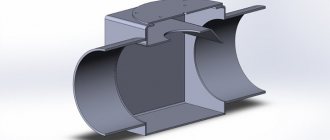
It turned out to be such a neat hole. Keep in mind that it will be a couple of centimeters wider than the box, because... we will cover it with basalt cardboard. From the inside the gap will be closed with the “ears” of the passage unit, and from the outside we will close it with a lid.
We prepare the ceiling passage unit for installation (in our case it is a wall passage unit). We trim off the excess according to the thickness of the house. Then we begin to cover it with basalt cardboard in three layers. Seven times measure cut once.
For ease of installation, we fix the side walls made of basalt cardboard to the box with self-tapping screws. We will cut off the excess basalt cardboard after installing the box in the hole prepared in the wall.
We install a prepared passage unit on the side of the boiler room. We additionally protect the wall with a sheet of heat-resistant board.
Next, we begin to prepare the horizontal chimney outlet. We fix the starting element of the sandwich to the boiler gate using heat-resistant sealant and self-tapping screws. Having determined how long the horizontal exit will be, we place it on the start sandwich. In our case, the length turned out to be 0.5 meters, quite a standard length of a sandwich pipe, so there was no need to cut it.
We close the passage unit with a lid (it is sold complete with the passage unit). We place a basalt cardboard gasket under the lid. The iron passage unit contacts the wooden wall (ceiling) only through a gasket made of non-flammable material, in our case it is three layers of basalt cardboard.
At the chimney exit from the room, we install a sandwich tee with an inspection. The inspection will allow you to service the chimney. Next we will have a sandwich chimney going vertically upward. Using a plumb line, mark the hole in the roof.
We prepare the passage unit in the roof. We make a hole, then a flange.
Since the chimney runs next to the wall, we shorten the wall brackets. The length of the bracket is determined in such a way as not to damage the jib and not to deprive the bracket of its strength.
We remove the chimney through the roof passage unit. The bracket is fixed only to the wall, its “leg” still walks freely. We will fix the bracket completely only after we have leveled the chimney. We fill the passage unit with basalt wool, install the gasket and close it with a lid.
Cooper boiler heating element connection diagram
05 Dec 2022 | Section: Electrics
Hello, dear readers of the site sesaga.ru. Tubular electric heaters ( TEH ) are designed to convert electrical energy into heat.
They are used as a basis
in heating devices (devices) for industrial and domestic use that heat various media by convection, thermal conductivity or radiation.
Tubular heaters can be placed directly in the heated environment, so their scope of application is quite diverse: from irons and kettles to furnaces and reactors.
Heating element device
The heating element is an electric heating element made of a thin-walled metal tube (sheath), the material for which is copper, brass, stainless and carbon steel.
Inside the tube there is a spiral of nichrome wire, which has a high electrical resistivity.
The ends of the spiral are connected to metal leads with which the heater is connected to the supply voltage.
The spiral is insulated from the walls of the tube by a compressed electrically insulating filler, which serves to remove thermal energy from the spiral and securely fixes it in the center of the tube along its entire length.
Fused magnesium oxide, corundum or quartz sand is used as filler.
To protect the filler from the penetration of moisture from the environment, the ends of the heating element are sealed with thermal and moisture-resistant varnish.
The heater leads are insulated from the walls of the tube and rigidly fixed with ceramic insulators. The supply wires are connected to the threaded ends of the terminals using nuts and washers.
The heating element works as follows: when an electric current passes through a spiral, it heats up and heats the filler and the walls of the tube, through which heat is radiated into the environment.
fins are used to increase heat transfer from heating elements.
, made of material with good thermal conductivity. As a rule, corrugated steel tape is used for fins, wound in a spiral on the outer shell of the heating element.
The use of such a design solution helps to reduce the overall dimensions and current load of the heater.
Schemes for connecting heating elements to a single-phase network
Tubular electric heaters are designed for a specific power
and
voltage
, therefore, to ensure the nominal operating mode, they are connected to a supply network with the appropriate voltage.
According to GOST 13268-88, heaters are manufactured for rated voltages: 12
,
24
,
36
,
42
,
48
,
60
,
127
,
220
,
380 V
, however, heating elements designed for voltages of 127, 220 and 380 V have found the greatest use.
Let's consider possible options for including heating elements in a single-phase network.
2.1. Plugging in
Heating elements with a power of no more than 1 kW (1000 W) can be safely plugged into an outlet through a regular plug, since the majority of electric kettles and boilers that we use to heat water have this power.
in parallel via a regular plug
two heating elements, but both heaters should have a power of no more than 1 kW (1000 W), since when connected in parallel their total power increases to 2 kW (2000 W). Thus, you can turn on several heaters, but their total power should be no more than 2 kW, and to plug into an outlet you must use a more powerful plug.
There may be a situation when you have several heaters lying around at home, designed for an operating voltage of 127 V, you can’t throw them away, and you can’t plug them into the home network.
In this case, the heaters are turned on sequentially
, which makes it possible to apply increased voltage to them. When two heaters with a voltage of 127 V are connected in series, their power remains the same, but the total resistance doubles.
For example, when two 500 W heaters are turned on, their total power will be 1000 W.
However, this scheme has one drawback: if any of the heating elements fails, then both will not work, since the electrical circuit will break and the power supply will stop.
You must also remember that when two heaters with an operating voltage of 220 V are connected in series, their total power decreases
twice as much, since due to the increase in total resistance, each heater will receive about 110 V instead of the required 220 V.
2.2. Switching on via circuit breaker
It will be much more convenient if voltage is supplied to the heating elements using a circuit breaker. To do this, it is necessary to provide a machine in the house panel, or install the machine directly next to the heating device. The voltage supply and shutdown will be carried out by turning on/off
circuit breaker.
The next option for turning on the heaters is carried out with a two-pole switch, which is the most preferable, since in this case the phase and zero are broken simultaneously and the heating element is completely disconnected from the general circuit. Voltage is supplied to the upper terminals of the switch, and the heater is connected to the lower terminals.
If an electric heater is used to heat water and the house is grounded
, then to protect against electric shock in the event of a breakdown of the heater insulation, it makes sense
to install an RCD
or a circuit breaker.
In this case, the grounding conductor
connected to the heating element body or connected to a special screw fixed to the container body. Next to such a screw there is a grounding sign. Let's consider a circuit with a difavtomat:
Protection with a difavtomat works as follows: when the heater insulation breaks down, a phase appears on its body, which, using the least resistance, will “go” along the PE
and will create
a leakage current
.
If this current exceeds the setting, the automatic circuit breaker will operate and turn off the voltage supply. If a short circuit
, then in this case the automatic circuit breaker will operate and de-energize the heating element.
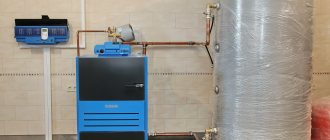
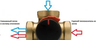
Additional mixing unit.
An additional mixing unit is mounted in the area between the buffer tank and the heating radiators. This element of the system connects the return and supply circuits and allows you to avoid strong temperature differences when the coolant almost begins to boil at the peak of the boiler operation.
By the way, for solid fuel boilers “Kupper” with an automatic pellet burner, an additional mixing unit is not needed and when installing them, you can safely limit yourself to the most primitive piping scheme.
In the Kupper OVK 10 model, an automatic pellet burner (APG) is installed in place of the ash door of the boiler, and the container into which pellets are loaded and the built-in control panel are installed on the boiler itself, which saves space in the room. Before starting the work process, the operating parameters of the heating system are set on the remote control. Using an automatic remote control, you can control the ignition, combustion process and maintain a balanced temperature of the coolant without the participation of additional mixing units that complicate installation. Another advantage of this model is that the ash is partially removed under the influence of a built-in high-power fan.
This boiler is suitable for installation in rooms up to 100 m² and can be used in a residential building, country house, garage, and other places. The equipment can be easily integrated into different types of heating systems. A nice bonus is the presence of a stove with a hob.
This boiler is suitable for installation in a residential building, country house, or garage.
Solid fuel boiler Kupper: how to select and install
The Kupper boiler is a solid fuel universal heating unit produced by the Novosibirsk company Teplodar. Despite the fact that the model entered the Russian boiler equipment market relatively recently, it was able to gain well-deserved popularity among buyers.
There is quite an explanation for this - heating units combine all the best achievements in the operation of modern solid fuel boilers, becoming a universal unit. It is difficult to find a similar model on the domestic market today.
Features and Benefits
Cooper solid fuel boiler has a simple operating principle and versatility in the use of solid fuel. It is loaded through a special door. Ignition is performed from below.
Water is supplied to the combustion boiler, made in the form of a water jacket. The efficiency of heating the coolant in this design is ensured by the multi-row design of pipes located in a checkerboard pattern, thereby ensuring the maximum possible contact of flue gases with the heated medium.
Fuel burning in the firebox transfers its heat to water, which at a temperature of 90-95 C is sent to the radiators. The movement of hot water can take place either according to the principle of natural circulation or forced circulation, using a circulation pump.
Flue gases, having given up their temperature to the network water, are released into the atmosphere through a smoke exhaust system consisting of a flue and chimney. The diameter of the exhaust gas outlet pipe for OK models is 150 mm, and for OVK – 120 mm.
Advantages of Kupper units operating on solid fuel:
- Multi-fuel - works not only on wood and coal, but also on electricity, main gas and pellets.
- Optimal ratio “cost - consumer quality”, lower price threshold from 20,000 rubles.
- Expanded functionality, food preparation permissibility for a number of models.
- A distinctive design solution and high quality paint coating.
- Optimal thermal insulation.
However, like absolutely all thermal power equipment, the Cooper PRO boiler has a number of disadvantages, which users include:
- Low level of brand awareness.
- A combustion heat exchanger made of steel has a shorter service life than cast iron.
- The package does not include a thermostat or control panel for heating elements; they must be ordered additionally.
- Single-circuit model, there is no possibility of obtaining hot water for domestic needs. To obtain hot water, it can be used in a circuit with an indirect heating boiler, which must be purchased separately.
Models and characteristics table
The Kupper line is quite wide, it includes both basic OK boilers and the “PRO” series. All models differ in design and technological parameters.
https://www.youtube.com/watch?v=XqgY8ZMogfMu0026t=309s
Consumers are offered multi-purpose configurations, long-burning modifications and standard solid fuel units.
Kupper units are presented on the market in the following basic versions:
- Boiler Cooper Praktik 8.
- Boiler Cooper OK 9.
- Boiler Cooper Praktik 14.
- Heating boiler Cooper Expert 15.
- Heating boiler Kupper OK 15.
- Boiler Cooper Carbo 18.
- Boiler Cooper OVK 18.
Classification of boilers “OK” stands for heating boiler, and “OVK” - additionally has a hob for food preparation.
In addition to the basic options, the Teplodar company produces a series of boiler units “PRO”:
- Boiler Cooper PRO 22.
- Boiler Cooper PRO 28.
- Boiler Teplodar Cupper PRO 36.
- Boiler Teplodar Cupper PRO 42.
These are multi-purpose units with the principle of long burning, a large loading chamber and a long period of operation on one load of firewood up to 8 hours. These solid fuel boilers are equipped with an additional chamber that produces pyrolysis gas.
Specifications
| Model | PRO – 42 | OK – 30 | OK – 20 | OK – 15 | OVK – 18 | OVK – 10 |
| Heated area, m2 | 420 | 300 | 200 | 150 | 180 | 100 |
| power, kWt | 42 | 30 | 20 | 15 | 18 | 10 |
| Dimensions, mm | 540820970 | 1000645422 | 745645422 | 740500340 | 745645422 | 740500340 |
| Heating range (°C) | 60/95 | 60/95 | 60/95 | 60/95 | 60/95 | 60/95 |
| Power of the heating element block (kW) | 3x3=9 | Zx2=6 | Zx2=6 | Zx2=6 | Zx2=6 | Zx2=6 |
| Type of fuel | WoodCoalPelletsBriquetsCokeGas Fuel OilPatSawdust | WoodCoalPelletsBriquetsCokeGas Fuel OilPatSawdust | WoodCoalPelletsBriquetsCokeGas Fuel OilPatSawdust | WoodCoalPelletsBriquetsCokeGas Fuel OilPatSawdust | WoodCoalPelletsBriquetsCokeGas Fuel OilPatSawdust | WoodCoalPelletsBriquetsCokeGas Fuel OilPatSawdust |
| Heat exchanger | Steel | Steel | Steel | Steel | Steel | Steel |
| Efficiency, % | 88 | 80 | 80 | 80 | 80 | 80 |
| Price, thousand rubles | 44.080 | 33.320 | 25.940 | 22.820 | 27.560 | 22.420 |
| Warranty, year | three | three | three | three | three | three |
| Weight, kg | 178 | 145 | 115 | 98 | 125 | 85 |
Accessories
Buyers, purchasing Kupper heating boilers, receive multifunctional, combined units capable of operating according to the schemes: “coal - electricity” or “main gas - electricity”, this allows you to evenly maintain the temperature in the rooms throughout the day.
All Kupper OK boilers are equipped with electric heating elements - 6 kW, and models over 30 kW - 9 kW. Particularly promising for the use of such devices is the use of a diphtariff electricity metering scheme, when at night it can be switched to electric heating with the lowest tariff.
Be sure to check the boiler delivery package
For comfortable controllability of a group of heating elements of the unit, there is a control panel (CP) with temperature sensors that control water heating and internal air temperature in the room. The system operates automatically and can turn on heating elements alternately depending on the set mode.
Cooper boilers can operate on main gas fuel or pellets. The buyer can order a gas injector AGG-13/26/40K with a power from 13 to 40 kW or a pellet injector APG-25/42. Both are mounted in the area of the fire door.
Installation procedure
The installation of the unit, piping of the heat supply system, flue, and gas burner device must be carried out by highly qualified craftsmen who have a license to perform such work.
The validity of the warranty for the device and the auxiliary equipment that comes with it will depend on this fact.
All work on installing the unit must comply with the Rules for the safe operation of water boilers with a coolant temperature not exceeding 115 C.
Basic requirements and installation procedure for Cooper boilers:
- The boiler is installed at a safe distance from flammable materials: from the walls - 50 cm, from the ceiling - 120 cm, and in front - 125 cm.
- A safety valve must be installed at the outlet pipe of the hot coolant DN 40 mm to protect the structure from high pressure.
- The heating system must be equipped with air vents and an expansion tank.
- The boiler is connected to the heating system using pipe threads.
- Connections to the power supply line must be carried out by a licensed organization with qualified, certified personnel and comply with the requirements of the Electrical Installation Rules. Each electric heating element must be connected with a copper cable higher than 1.5 mm2 and 16 A circuit breakers. Parallel connection of 3 electric heating elements through a 30 A circuit breaker and a cable with copper conductors of at least 4 mm2 is allowed.
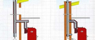
- To remove flue gases from the boiler, it is recommended to install stainless steel thin-walled pipes supplied by the same manufacturer. The best option for such devices is the installation of ready-made blocks with sandwich thermal insulation.
- It is allowed to use a brick chimney with a channel cross-section of at least 200 cm2, which must be uniform along the entire length.
- The height of the flue, starting from the grate, is at least 5 m.
Tips for use
Cooper boilers are classified as objects of increased fire danger; boiler owners must maintain the units in full compliance with factory instructions and fire safety rules.
It is allowed to ignite the boiler only after filling the heating system with water. Preliminarily check the presence of draft in the gas path. To do this, light the paper and bring it to the ash pit; if the fire is drawn into the boiler, then the draft is normal.
Requirements for the operation of a solid fuel boiler Kupper:
- Kindling begins with dry firewood, filling the firebox up to 1/2 of the height. Subsequently, when the flaming coals cover all the grates, load the coal.
- Loading of coal is carried out in small parts of 5 kg, and the door should not be left open for a long time, so as not to allow a large amount of cold air to enter the combustion chamber.
- During the combustion process, the intensity of the process can be controlled by regulating the air supply by rotating the screw and providing draft with a rotary gate.
- The temperature of the flue gases is controlled, which should be at least 150 C. This mode will guarantee the absence of bitumen deposits on the inner surface of the chimney and maintain stable draft.
- During operation, it is necessary to ensure the cleanliness of the heating surfaces and prevent soot from growing more than 1-2 mm. Since such deposits lead to a sharp decrease in heat transfer and efficiency of the unit.
- Boiler owners must conduct an annual inspection of their equipment before the start of the heating season.
- To reduce scale formation in internal heating surfaces, it is recommended to soften the make-up water.
- The Cooper boiler is not allowed to be operated at a return coolant temperature below 60C. Because in this mode, condensate is intensively created in the flue gases, which contributes to corrosion damage to the heat exchanger and chimney system.
A fairly wide range of models, budget price, attractive design and excellent build quality set Cooper solid fuel boilers apart from the list of similar units.
They already have many modern technological innovations and continue to improve, which in turn delights customers.
Boiler room installation.
Preparing a room for a boiler room involves finishing surfaces with non-flammable material, providing ventilation, and installing windows.
One of the most important stages that should be taken as seriously as possible is the arrangement of the boiler room (furnace room) - the room in which the boiler is supposed to be installed. The boiler room must be equipped in accordance with all fire safety requirements, including:
The solid fuel boiler must be installed in a separate non-residential premises, the area of which must be at least 7m2. Please be aware that when using solid fuels, some dust and smoke will be generated. The optimal places to place a solid fuel boiler if you do not want or do not have the opportunity to equip a separate boiler room are a garage or basement. A window is required.
For the smooth and efficient operation of heating equipment, it is necessary to have high-quality supply and exhaust ventilation. This is primarily due to the fact that normal combustion of fuel requires a large amount of oxygen. Experts recommend choosing a combined type of ventilation system, which involves organizing a natural flow of outside air through a ventilation hole and forcing it out into the street through a special outlet equipped with an electric fan.
The floor, ceiling and walls of the boiler room must be finished with fire-resistant materials. The best option is ceramic tiles. A concrete screed with a thickness of at least 5 cm should be made on the floor. In an emergency, these measures will prevent the spread of flame to other rooms of the house and generally increase the safety of using a solid fuel boiler.
Also, in order to ensure fire safety, it is necessary to leave as much free space around the boiler as possible and not install it close to the wall.
Device and connection diagrams of heating elements | For home, for family
Room thermostats can be divided by device, by method of device and by functionality.
Based on their technical design, room thermostats can be divided into 3 types:
- Electromechanical.
- Electronic.
- Mechanical.
According to the method of installation, room thermostats are divided into two types:
- Wireless thermostats. Using periodic signals, communications between the executive unit and the controller are carried out. Wireless thermostats have a big advantage: there is no need to make holes for wires. But there is also a small drawback: the signal power is reduced due to reinforced concrete walls.
- Wired thermostats. Contacts between blocks are maintained using wires. Such a thermostat can transmit data over a distance of more than 50 meters. The power source can be a household electrical network.
Based on functionality, the following types of room thermostats can be distinguished:
- Programmable thermostats. They can set the desired regime for several days in advance.
- Simple thermostats. They only maintain the required temperature.
- Room thermostats cannot create a harmful electromagnetic field. They only transmit a small impulse.
How to connect a thermostat to an infrared heater
Electrical wiring can be open or hidden.
Is it possible to use one thermostat in several rooms?
When installing a thermostat, it is necessary to take into account that the set temperature will be maintained only in the place where the sensor is located. Cables laid in several rooms must be connected in parallel, as when one heating cable to the thermostat
You should not use one thermostat when the operating conditions of the premises are different (bathroom and kitchen), and also when the rooms have different heat loss rates (room and balcony).
Choosing an electric boiler for your home
To choose the right electric boiler for heating your home, you need to consider many factors. including the material and thickness of the walls, glazing area, outdoor air temperature in winter in your region, ceiling height and many others.
Often, such calculations are entrusted to specialists who make a home heating project that takes into account all the necessary characteristics of the system, including the type and power of the electric boiler; often they even offer a specific model or several to choose from.
When independently choosing the required power of an electric boiler for heating, it is usually customary to use the following formula: 1 kW of power is required to heat 10 sq.m. Houses.
The rule is relevant for single-circuit boilers used only for heating rooms, but if there are two circuits, one of which is used to heat water in the hot water supply system, the calculation must be changed, the same should be done if the ceiling height is higher than the standard 2.5-2.7 m and in some other cases.
So, in our example, the area of the house is 120 sq.m. Therefore, an electric boiler with a capacity of 12 kW was chosen . model ZOTA - 12 series "Econom".
After all the theoretical calculations, we will determine whether this boiler is suitable for the permitted (allocated) power for the house. For us it is 15 kW, with a three-phase input, so a 12 kW boiler is suitable for us in terms of power.
Of course, if the electric boiler operates at its maximum capabilities, only 3 kW of the permitted amount will remain for the remaining consumers of the house, which is quite small. But since the boiler will be a backup one and will only turn on when the main gas boiler is faulty, this decision was made acceptable.
Flaws
Fragility is the main drawback of heating elements for heating with a thermostat.
Firstly, the tubular heater itself interacts with salts dissolved in water. As a result, scale grows on the tube, which leads not only to a decrease in efficiency, but also to damage to the heater. As a means of protection against plaque, some models install an additional rod - a magnesium anode.
Since magnesium is a chemically more active substance, salts preferentially interact with it, and the heating element is provided with protection against scale. And again, the disadvantage is that the protection rod slowly decomposes in a chemical reaction and eventually requires replacement.
And although replacing the anode is not a complicated process at all, which, like automation, does not require disassembling the entire structure, the inconvenience is the need to constantly monitor the presence of the reagent.
Inserting heating elements into the home heating system
If you want to replace or find a backup heat source for your solid fuel boiler, such as, for example, Don, Cooper, Evan, Breneram Aquaten or Teplodar, this option is perfect because it is not very labor-intensive and financially expensive.
When carrying out such a procedure, observe safety measures, since any activities using electrical energy are extremely unsafe.
Let's take a closer look at how to connect the heating elements on the boiler. When using it as a backup heating method, be aware of changes in pressure level; it is recommended to use a pump to equalize it.
Let's look at how to install such a device step by step:
- You need to check the direction of the thread in the pipe and measure its diameter.
- Drain the coolant.
- Check the level of the radiator, since at the slightest inclination there is a high probability of air pockets accumulating. Air lock in the heating radiator
- Install the heating element into the pipe. To ensure that the hole is sealed, use the gaskets that come with the kit; if they are not available, make them.
- Connect the heating element and thermostat to the radiator.
- If you have not previously installed a Mayevsky faucet, install it. Because it will be necessary to bleed air from the system.
Then fill the system with liquid, using the Mayevsky tap to release the accumulated air. Using a tester, check that the heating element is isolated from the battery to avoid electric shock; if a breakdown is still present, check the serviceability of the heating element. If its insulation is broken, it needs to be changed. Then perform the installation again.
Connection diagram of an electric boiler to a 380 V three-phase electrical network
The general electrical diagram for connecting a 380 V electric boiler is as follows:
As you can see, the line is protected by a three-phase residual current circuit breaker; grounding is necessarily connected to the boiler body.
As usual, according to tradition, I am posting a connection diagram for a three-phase electric boiler with a combination of an automatic switch (AB) plus a residual current device (RCD) in a circuit, which is often cheaper and more accessible than Diff. machine.
It is convenient to select protective automatic ratings and cable cross-sections for three-phase electric boilers of various capacities using the following table:
In three-phase electric boilers, three heating elements are usually installed at once, sometimes more. Moreover, in almost all household boilers, each of the tubular electric heaters is designed for a voltage of 220 V and is connected as follows:
This is the so-called star connection. For this case, the neutral conductor is connected to the boiler.
The heating elements themselves are connected to the network as follows: one end of each of the tubular electric heaters is connected by a jumper, the remaining three free phases are alternately connected: L1, L2 and L3.
If your boiler has heating elements designed for a voltage of 380 V, their connection diagram is completely different and it looks like this:
This connection of the heating element of an electric boiler is called a “triangle” and at the same voltage of 380 V, as in the previous “Star” method, the boiler power increases significantly. In this case, a neutral conductor is not required, only phase wires are connected, and the electrical connection diagram looks like this:
Do not deviate from the connection diagrams permitted for your electric boiler. if there are heating elements for 220V with a three-phase connection, do not convert the circuit to a “triangle”. As you understand, theoretically you can reconnect them and get a voltage of 380 V on the heating element, respectively, increasing their power, but in this case they will most likely simply burn out.
How to determine the correct connection diagram for heating elements with a star or triangle and, accordingly, what voltage they are designed for?
If the instructions for connecting your electric boiler are lost or there is simply no way to refer to them, you can determine the correct connection diagram at home as follows:
1. First of all, inspect the terminals of the heating element; most likely, the manufacturer has already prepared the contacts for a specific circuit. So, for example, for connecting a star and heating elements for 220V, three terminals will be connected by a jumper.
2. The very presence of the zero terminal - “N”, indicates that the heating elements are 220 V and they must be connected according to the “Star” circuit. Moreover, its absence does not mean that the heating element is 380 V.
3. The most reliable option to find out the voltage of the heating element is to look at the markings. indicated either on the flange to which the tubular electric heaters are attached
Or, on the heating element itself, its parameters are necessarily extruded:
If you cannot find out for sure the voltage for which your electric boiler is designed and the connection diagram for its heating element, but you “really need to” connect it, I advise you to use the “Star” circuit. With this option, if the heating elements are designed for 220 V, they will work normally, and if they are rated at 380 V, they will simply produce less power, but most importantly they will not burn out.
In general, there are different cases, and it is very difficult to cover them all in the format of one article. ,
Purpose of the strapping
For TTK, as for other types of equipment, it is important to correctly combine all components into a single system and connect peripherals.
The TTKO harness performs the following functions:
- Reducing the negative impact on others in the event of any emergency.
- Uniform distribution of generated heat throughout the entire circuit of the heating system.
- Reducing the periodicity factor in the operation of TTKO associated with uneven fuel combustion.
All of the above points lead to increased safety and efficiency of the boiler.
What elements does the harness consist of?
For all heated buildings, a single connection scheme and equipment configuration simply does not exist. Therefore, before starting heating installation in the house, an individual project is carried out.
List of mandatory elements that must be present in the harness:
- Boiler.
- Radiators or batteries.
- Expansion tank.
- Pipes (cast iron, copper, steel, polypropylene).
- Fittings and fittings (including Mayevsky taps and pressure gauges).
- Circulation pump (if there is forced movement of the coolant).
- Bypass lines.
- Thermostat.
Boiler piping rules
For efficient and reliable operation of the heating system as a whole, the TTKO should be properly tied.
There are several important points to consider:
- To avoid the formation of condensation, ensure that the temperature difference between the supply and return is no more than 20 °C.
- Installing pressure gauges will allow you to control the pressure within the limits specified in the equipment instructions and regulatory documents.
- To ensure maximum efficiency, connections must be sealed.
- The use of flammable materials in the strapping elements is not allowed.
- In order to avoid scale formation and clogging of pipelines, leading to equipment failure, it is necessary to monitor the cleanliness of the coolant.
- If the building is higher than one floor, forced coolant circulation should be used.
How to correctly change the heating element on a heating boiler or install it into the heating system
The first thing you need to pay attention to is the rated power of the heating element. By installing a device with low power, you will not receive enough thermal energy, while consuming a large amount of electricity. And by setting an unacceptably high power, there is a high probability of constant overheating of the device, and an explosion is possible.
As for its location, it must be completely immersed in water, otherwise it will overheat; as a rule, it is installed at the bottom of the radiator.
This makes it possible to isolate it from places where air accumulates.
In order for it to last longer and less plaque to accumulate on it, which leads to a significant loss of efficiency, as well as to corrosion, you need to use distilled liquid.
It is very important, when you insert a heating element or a block of heating elements into the heating system, to properly seal the end joints, because if liquid gets on the heating element (coil), there will be a threat to the residents of the house. Let's consider the option of connecting to electrical networks with different numbers of phases.
If you have one phase, often this option is most typical for cottages or old buildings, you need to install a fuse. It is characterized by the presence of two conductors: phase and zero. There are two connection methods - parallel or serial, the difference is in dividing the original voltage between the components.
More often, the connection is made in parallel to minimize the loss of useful energy. The sequential circuit is used extremely rarely, as it involves energy losses. For any of the selected circuits, it is necessary to choose a wire with a large cross-section, since it will carry a large load.
Connection to three phases - the first method is the so-called star, it involves feeding from a 220 V network with a neutral wire supplied from the panel. One jumper is used, connected to zero, and the remaining three free ends are connected to the phases.
Triangular connection, the incoming voltage in this case is 380 V. By connecting heating elements intended for use at 220 V here, you risk damaging them because they will burn out. The difference between a triangle and a star is the absence of a neutral conductor.
Installation of the mixing unit.
After completing the installation of the safety group, you can begin installing the mixing unit - a return jumper that connects the supply circuit of the heating system with the return circuit. During operation of the system, the liquid, bypassing the heating devices, gives off heat and returns to the boiler for heating.
If this circuit operates correctly, when the coolant temperature drops below 60°C, the jumper will open automatically, a small volume of hot water will enter the return circuit and the temperature will return to the desired value.
Solid fuel boilers "Kupper" are universal heating equipment capable of operating in open and closed systems, where forced or natural coolant circulation is provided. Such a boiler can act either as an independent source of heat energy, or as an additional one - as part of an existing heating circuit, in tandem with another boiler running on gas, electricity or liquid fuel.
An additional advantage of purchasing a Kupper boiler is that a thermometer for temperature control is included with the heating equipment.
How to connect a heating element to a Cooper boiler
There is a generally accepted formula with which you can correctly calculate the required power; calculations are performed based on the fact that 1 kW of energy is spent to heat 10 m2 of room area. It looks like this:
m is the volume of the heated liquid,
t1 is the final temperature of the liquid, degrees Celsius,
t2 is the initial temperature of the liquid,
t is the period during which the liquid is heated, min.
P is the power of the heating element.
Let's try to make a calculation for an aluminum battery of 6 sections, the volume of liquid contained is about 4 liters. It is necessary to heat the radiator from 15 degrees to 60 in 15 minutes. We perform the calculation:
P=0.0066*4 (60-15)/15=0.792, so the power should be 0.8 kW.
about connecting the heating element to a single- and three-phase network:
Introduction
You are planning or have already purchased a direct-flow electric boiler for the heating system of your home. I suggest you get acquainted in advance with the features of connecting such boilers, and see what the connection diagram for an electric boiler looks like.
About electric boilers
A classic electric heating boiler, one might say a default boiler, the type of which is not specified, is considered to be electric boilers with heating elements.
TEN is an abbreviation for tubular electric heater. The analogue you see in an electric kettle with a spiral.
Depending on the number of heating elements in the boiler, their power changes. Since heating elements are often standard, the power of electric boilers from different manufacturers is also standard. This is 6/9/12/14/18/21/24/28 kW.
It is worth noting that the concept of an electric boiler is much broader than just heating element boilers. Induction and electrode boilers, which are also electric, have become widespread.
Electric boiler connection diagram
The general connection diagram for an electric boiler with heating elements is nothing more than a diagram for connecting one or more heating elements to the power supply.
To understand and understand the principle of connecting a heating element boiler, let’s look at the heating element.
In the photo you see the simplest heating element, consisting of one heating tube. As a result, such a heating element has only two contacts for connection. This heating element is connected directly. One contact per phase (usually 220 Volts), the second contact to working zero.
The power of such heating elements is small and they are not used in heating boilers. Their prerogative is kettles or washing machines, dishwashers.
In electric boilers, heating elements are “curled” from two, often three, tubes. The heating element for the boiler looks like this.
As you can see, such heating elements already have 6 (six) contacts for connection and this is the simplest option. The task of connecting the heating element of the boiler is to correctly connect the six contacts of the heating element to connect it to the power supply.
There is nothing complicated about this if you recall two classic connection diagrams from the electrical engineering course. You've probably heard of them, these are circuits called "star" and "triangle". I wrote about them in some detail in the article How a low-voltage consumer of 380 Volts receives electricity.
I will describe these schemes in simple language. So, we have 6 contacts divided into pairs. Only three pairs.
- The “star” circuit involves connecting one contact from three pairs and connecting it to the working “zero”. The remaining contacts of the heating element pairs are connected to phases L1, L2, L3 if the power is 380 V, or they are also connected and connected to phase L if the power is 220 V.
- According to the “triangle” circuit, all pairs of contacts are connected in series and connected to three phases of 380 V.
On practice
If you buy a ready-made boiler and do not assemble it yourself, then you will have a boiler control unit that will have terminals for connecting the power supply.
The only thing you need to do is to correctly calculate the cross-section of the power cable and the rating of the circuit breaker for the boiler.
Let me briefly remind you that these calculations are carried out based on the boiler power using tables 1.3 of the PUE. Since aluminum will soon be returned to electrical installations, I will provide summary tables from which you can select the cable cross-section according to the power of the device for copper and aluminum wires (cable cores).
This table for selecting cable cross-sections and protection devices for Protherm Skat boilers will also help.
Conclusion
The connection diagram for an electric boiler with heating elements is considered. With basic knowledge of electrical engineering, you can assemble such a boiler yourself.
How to connect heating elements of an electric boiler
Greetings, my readers! I decided to write this post for those who are trying to figure out how to connect an electric boiler to the wiring.
The article is devoted to heating devices using heating elements as heating elements. I will write about electrode boilers separately.
There are several options for performing this operation, and I will discuss them below in turn. We start, as you may already be accustomed, from simple to complex.
Heating element and single-phase network. screw what to what?
This case is typical for dachas and old-built village houses. First you need to generally understand what we are talking about and the easiest way to do this is by looking at the following figure:
So, a single-phase electrical network has two conductors - zero and phase. The picture itself shows two ways to turn on the load - parallel and serial.
These methods differ in how the initial voltage is divided between the elements. In most cases, heating elements are connected in parallel so as not to lose useful power; a series circuit is suitable only for various specific cases.
A block prepared for connection to one phase will look like this:
It is also worth paying attention to the choice of cable, but we will touch on this point a little later, and now let’s move on to the three phases.
Two ways to connect heating elements to three phases
“Three-phase” used to be something not very necessary and understandable for the common man, but in our time it has become a necessity for a private home. It is needed primarily for heating with electricity.
Since an electric boiler has a high power (in most cases more than 6 kW), when using one phase you will need to install cables with a large cross-section of conductors. And this will be expensive, especially if the cable cores are made of copper.
In a three-phase network, the cross-sections of the conductors will be noticeably smaller, for this reason most modern electric boilers are connected to a “three-phase” system. Now let's talk about the basic schemes for connecting heating elements to such a network.
Video
This video discusses possible reasons for poor performance of a solid fuel heater.
Evgeniy Afanasyev chief editor
Author of publication 01/22/2019
Did you like the article? Save so you don't lose!
When installing a heat generator heat generator in a boiler room, the piping of a solid fuel boiler most closely resembles the same circuit for a diesel unit. Why? Because, as you know, there are no wall-mounted TT boilers, just like diesel ones. All other heat generators - gas, electric, etc., are wall-mounted.
Accordingly, in many cases, piping a solid fuel heating boiler can be implemented in the same way as for other floor-standing boilers. At the same time, the connection diagram for a solid fuel heating boiler still differs in a couple of points. About them - below.
Equipment Specifications
The width of the chimney varies depending on the power of the unit.
You can consider the technical parameters of a boiler from the Cooper company using the OK-15 model as an example, since the entire heating line is similar:
- Efficiency is 80%, but this characteristic varies by 5%;
- operating pressure parameters in the presence of water – 0.2 MPa;
- maximum coolant temperature – 90 degrees;
- water temperature at the entrance to the circuit is 60-80 degrees;
- smoke exhaust duct diameter – 150 mm;
- thermal power – 9, 10, 15, 18 and 20 kW.
The chimney modification OK-10 is 115 mm in diameter.
Calculation of device power
In order not to overpay for electricity and prevent emergency situations, it is necessary to calculate the required power before installing heating elements in the heating system. And it won’t be possible to do this “by eye”. Calculations are made based on the fact that for heating 10 sq.m. the premises require 1 kW of thermal energy. The formula for calculating the power of the heating device is as follows:
where Pm is the design power, m is the mass of the coolant, T1 is the initial temperature of the coolant before heating, T2 is the temperature of the coolant after heating and t is the time required to heat the system to the optimal temperature T2.
Let's consider calculating power using the example of an aluminum radiator in 6 sections. The coolant volume of such a radiator is about 3 liters (precisely indicated in the model data sheet). Let's say we need to heat the radiator by connecting the heating element to the heating battery, in 10 minutes from 20 degrees to 80. We substitute the values into the formula:
Рм=0.0066*3(80-20)/10 = 1.118. that is, the power of the heating element should be about 1-1.2 kW.
The heating element is installed in the lower section of the heating radiators
However, this is only valid if water is used as the coolant. If you need to make calculations for oil or antifreeze. then a correction factor is applied, which is about 1.5. Simply put, the power of heating elements for heating oil heaters should be increased by about one and a half times. Otherwise, the estimated time to reach the optimal temperature will increase.
