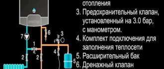
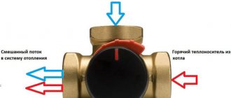
List of structural elements of the Stropuva boiler.
In the previous article we talked about long-burning stoves for homes, cottages, bathhouses, and how to heat them. Today we will talk about two units that are similar in their principle of operation - the Lithuanian boiler Stropuva and the Bubafonya from Kolyma, and we will even try to compare them. Those who think whether it is possible to make a Stropuv boiler with their own hands will have to be disappointed, most likely this will not be possible.
Some structural elements are very complex and can only be manufactured in production conditions using machine tools. But a domestic, simplified analogue can be assembled in a day. Of course, it does not have such high characteristics as factory units, however, it will heat a dacha or garage in no time. The option is super economical and practical, like the AK-47.
Description of connecting the Stropuva boiler piping:
Description of the scheme
The coolant heated in the boiler passes through steel pipes with a diameter of 25 mm for boilers S40, S20, S10, S8, S7. Air is removed from the boiler through an automatic air vent (1). A safety valve of 1.5 atmospheres is installed on the external circuit of the boiler. The coolant is directed along the external circuit through the valve to the hot water boiler (3).
After heating the boiler, the coolant flows back into the outer circuit of the piping unit. After the boiler (3), a selection is made to an additional radiator (4) which, in the event of a power failure, can operate as a gravity-fed one. The additional radiator (4) must be connected independently. It is necessary to prevent the boiler from overheating when the circulation pump (6) is turned off.
The radiator system (5) is connected at the top of the small circuit through a valve with a diameter of 25 mm. The return line of the radiators is fed to the circulation pump through a valve with a diameter of 25 mm. The heated coolant from the boiler enters the heating system manifold and then into the radiator system (5). The cooled coolant flows from the return manifold to the circulation pump (6). The return coolant after the pump (6) is supplied to a three-way mixing valve (7).
The mixing valve (7) is necessary for mixing the coolant in the return and supply lines to prevent the formation of condensation and is necessary for adjusting the temperature regime of the boiler. In the lower part of the circuit, after the mixing valve, a balancing valve (8) is installed with the ability to adjust the passing flow, with the help of which the flow from the circulation pump is distributed so that it is enough to heat the radiators, and at the same time, so that it is sufficient for the boiler
In the return line after the balancing valve, drain valves are installed to recharge and empty the system, as well as an expansion tank (9). The pressure in the expansion tank should be 0.5-0.7 atmospheres. If necessary, an electric boiler can be installed instead of a boiler.
A circulation pump with a power of:
- for boiler 10 kW 25–60 W
- for boiler 20 kW 40–80 W
- for boiler 40 kW 50–100 W
Bubafonya stove with water jacket
Pyrolysis furnace Bubafonya from a gas cylinder with a water jacket.
Finally, we got to the domestic analogue of the Stropuva boiler, which is much simpler to implement, since it has a non-folding pipe for supplying air to the firebox. There are already so many instructions on how to make a Bubafonya stove with your own hands that only a blind person would not have seen them, unless, of course, they were interested in this topic. And why all? Yes, because the process is so simple and if you take the matter seriously, you can get a finished product from scratch in a day. What is the Bubafonya stove made from with your own hands:
- from a gas cylinder;
- from a barrel;
- from pipes
It can be either round or square. Let’s not repeat the same thing, just read the article: “Bubafonya stove from a gas cylinder” - and everything will become clear to you. Today we will consider a version of the product with a water circuit, as if we will try to repeat the principle of operation of the Stropuva boiler. All that is required is to make a simple Bubafonya and insert it into a pipe of a larger diameter. Thus, we obtain a gap in which the coolant will be heated.
Naturally, this space above and below is sealed so that various debris does not get there. What is important when making a Bubafonya stove with a water jacket with your own hands:
- use of heat-resistant steel;
- wall thickness of at least 4 mm;
- the presence of a tap for draining and replenishing water.
Immediately provide a hole in the upper part through the outer and inner walls for installing a chimney into it. There should also be enough space for water. The distance from the outer to the inner wall is about 10 cm. When connecting, do not confuse the supply and return pipes (supply from above).
Reservation of work
The Stropuva boiler will delight you with long-lasting fuel combustion. But even in this case, you can miss the moment of the next bookmark. As a result, the temperature of the coolant in the heating circuit will begin to fall. To prevent this from happening, we recommend installing a backup electric boiler in the circuit. If it detects a temperature drop below the set limit, it will turn on and maintain the set temperature.
Electricity consumption will be small if you don’t forget to add firewood for 2-3 days. The vast majority of the time the boiler will burn, providing heat to consumers. Therefore, you should not expect huge expenses. In addition, the auxiliary boiler does not have to be as powerful as the main one - a model with a power 2-3 times lower is quite enough so as not to make your teeth chatter in the morning. We also recommend working on insulating your home so that it retains the accumulated heat longer.
Manufacturing sequence
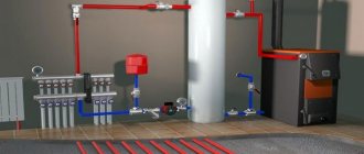
Type of homemade installation
- A lid with a small side is cut out of the barrel, for which a grinder is used. A hole is made in the lid right in the middle for a pipe with a diameter of 100 mm.
- Next, a grate is made from wire or corners. In fact, this is a regular grill, where it is important to determine the size of the cells. The smaller they are, the better, especially when it comes to such small fuels as sawdust or husks. By the way, the grate is not used in all models - sometimes you can do without it. If there is one, then it is installed inside the barrel closer to the bottom. Fastening is done by electric welding.
- Now let's move on to making the load - the press. To do this, a round pancake is cut out of a 4 mm thick steel sheet, the diameter of which is 2–3 cm less than the diameter of the metal barrel. A through hole with a diameter of 100 mm is made in it.
- We weld the pipe to the pancake. Please note that the length of the pipe should be 20–50 cm greater than the height of the barrel. Now 4 channels need to be welded on the back side of the pancake. They are needed to weigh down the press and create a small space under it - this will be the combustion zone. The channels are welded in such a way as not to cover the hole in the pancake. The usual fastening pattern is criss-cross.
- In the barrel just above the location where the grate is installed, you need to make a door through which you can clean the boiler from ash and ashes. This device must be sealed using an asbestos cord.
- A through hole is made on the side of the upper part of the barrel, almost near its upper edge, and a small pipe with a diameter of 100 mm is welded to this place from the outside. This will be the location where the chimney will be installed.
- Now you need to take care of the removable cover. The upper part of the barrel, which was cut out, must be brought into proper shape. To do this, its sides are slightly expanded - you can simply tap them with a hammer. It is necessary to weld two handles on the top side, with the help of which the cover will be installed manually. On the outside of the side around the entire perimeter, you need to glue an asbestos cord or a strip of fiberglass, which will contain the smoke coming out of the combustion zone.
At this point, all parts of the boiler are ready, and you can begin adding fuel, as well as assembling the structure.
Procedure for assembling the structure
Attention! The closer you pack the firewood, leaving minimal space between them, the longer it will burn. As for sawdust, everything is simpler - you just need to compact it well.
Combustion chamber
The press is installed on the stored fuel with the pipe facing up, and the barrel lid is put on it. The chimney is connected to the pipe. Long-burning furnaces have a unique design that ensures the removal of carbon monoxide only through a horizontal pipe. That is, the chimney will not be vertical, but horizontal with a slight upward slope. This is another distinctive feature of long-burning stoves.
Before placing the press, it is necessary to ignite the top layer of fuel. Then the press and lid are installed. In this case, the firewood or sawdust in the combustion zone will simply smolder, releasing a large amount of thermal energy. At the same time, as it burns out, the zone will gradually settle under the influence of the load. Smoke from the combustion of solid fuel comes out of the zone between the gap formed by the walls of the barrel and the edges of the metal pancake. It is then discharged through the chimney. Oxygen enters the combustion zone through a pipe welded vertically to the pancake.
Since the metal from the barrel will become very hot, the structure is considered unsafe in terms of fire. Therefore, experts recommend:
- Install such a stove near walls that are built from non-combustible materials.
- A foundation needs to be poured under a long-burning furnace. It can be concrete or fire brick.
- To increase operational safety, you can install a protective heat shield made of metal or bricks.
How to start a Stropuva boiler
First, you need to purchase a piping kit to connect the equipment to the heating system. We recommend purchasing a kit with the ability to connect an indirect heating boiler. It includes a set of pipes, a safety group, an expansion tank and a circulation pump. Also on sale are kits for connecting underfloor heating.
It is not recommended to use damp firewood - this will interfere with the normal operation of the boiler.
Ignition is carried out in the following way - here are brief instructions for use:
- We load the wood combustion chamber full with the air distributor raised.
- We fill the finished masonry with sawdust.
- Open the flap for switching to wood.
- Open the air damper 3-5 cm.
- We light the top layer, close the loading door, leaving a gap 3-5 cm wide.
- We wait for reliable combustion, close the loading door and immediately lower the air distributor.
Please note that the cleaning door must be closed. A new portion of firewood can be added to the Stropuv boiler at any time, but doing this with coal is dangerous. In any case, the manufacturer recommends that you always wait until the fuel burns out completely before adding a new portion.
In any case, the manufacturer recommends that you always wait until the fuel burns out completely before adding a new portion.
A new portion of firewood can be added to the Stropuv boiler at any time, but doing this with coal is dangerous. In any case, the manufacturer recommends that you always wait until the fuel burns out completely before adding a new portion.
Options for connecting the boiler to heating system lines
Connecting gas boilers
When it comes to gas heating boilers, it is possible to implement their connection to CO in several ways.
a. Direct connection of a gas boiler
Most often used in simple RMs. This assumes that the boiler has all the equipment necessary for this (safety group, expansion tank, circulation pump).
b. Connecting a gas boiler through a hydraulic separator
If you plan to install a complex heating system in your home, including low-temperature (warm water floors) and high-temperature (radiator) elements, then it is necessary to eliminate the “mismatch” in the movement of the coolant that occurs during operation. To do this, a hydraulic separator must be included in the piping, which performs the necessary hydraulic isolation. In fact, two coolant movement circuits are formed in the CO: the boiler circuit and the general CO circuit. Each of them has its own central control center. c. With additional heat exchanger
Installation of said element ensures waterproofing of said heating circuits from each other. The need for such a solution is due to:
- • use of different types of coolant (antifreeze and water) in circuits;
- • when combining closed and open systems within a single SO. Each of the circuits is equipped with its own central pump, make-up and drain taps, and safety groups.
d. Connecting a gas boiler using indirect heating boilers
The presence of the mentioned element in the CO allows you to constantly have a certain supply of hot water in the house, which is heated by the heat taken from the coolant operating in the CO. As a rule, these boilers are connected through special priority valves (three-way). If the house is large and the CO is multi-circuit, then this boiler is connected after the hydraulic separator.
Connecting solid fuel boilers
A specific feature of the mentioned types of boilers is their lack of a heat supply control function. It is impossible to interrupt the combustion of fuel. This, in the event of a power failure and the central heating unit stopping, can lead to the fact that continued heating will cause an increase in pressure in the lines, which can damage the CO.
To eliminate such a situation, several options for emergency schemes are being implemented to dump excess heat:
- • Connecting pumps to the battery;
- • Prompt supply of cold coolant (water);
- • The presence of a circuit operating in the mode of gravitational circulation of the coolant;
- • Connection of an optional emergency circuit.
Double-circuit solid fuel boilers are not recommended to be used in conjunction with gravity circulation systems.
Connecting electric boilers
If the boiler is an electrode model, then it is required in the heating circuit. Install: pressure gauge, air vent, non-return safety valve.
If the system is open, then in the pipeline, immediately behind the expansion tank. It is necessary to install shut-off valves.
Types and technical characteristics
At the moment, Stropuva is available in three varieties: wood-burning, pellet and universal. Each of these three varieties is designed for a specific type of fuel, but can work on any other, albeit with less efficiency. In total, the line includes 4 standard sizes: 10, 15, 20, 40 kW and a Mini version with a power of 8 kW.
The Stropuva wood-burning boiler is equipped with a special air distributor, which allows efficient burning of wood, and has the following characteristics:
| Model | Mini S | S10 | S15 | S20 | S40 |
| power, kWt | 8 | 10 | 15 | 20 | 40 |
| Room area, m² | 30-80 | 50-100 | 75-150 | 100-200 | 200-400 |
| Efficiency, % | 86,3 | ||||
| Firewood capacity, dm³ | 120 | 150 | 200 | 230 | 360 |
| Chimney diameter, mm | 160 | 180 | 200 | ||
| Burning duration, h | 31,5 | ||||
| Price, rub | 65 000 | 87 150 | 92 348 | 97 545 | 107 730 |
The pellet version is equipped with a distributor for fuel pellets and an air supply manifold. Boilers operating on pellets have the following data:
| Model | Mini SP | S10P | S15P | S20P | S40P |
| power, kWt | 8 | 10 | 15 | 20 | 40 |
| Room area, m² | 30-80 | 50-100 | 75-150 | 100-200 | 200-400 |
| Efficiency, % | 86,3 | ||||
| Pellet capacity, kg | 50 | 70 | 110 | 120 | 200 |
| Chimney diameter, mm | 160 | 180 | |||
| Burning duration, h | 72 | ||||
| Price, rub | 65 000 | 91 350 | 97 072 | 102 795 | 112 980 |
The last representative of solid fuel boilers is universal. These devices can operate on coal, wood, fuel briquettes and pellets. The delivery set includes distributors for all types of fuel, as well as an air supply manifold. They have the following technical characteristics:
| Model | Mini SP | S10P | S15P | S20P | S40P |
| power, kWt | 8 | 10 | 15 | 20 | 40 |
| Room area, m² | 30-80 | 50-100 | 75-150 | 100-200 | 200-400 |
| Efficiency, % | 86,8 | ||||
| Pellet capacity, kg | 50 | 70 | 110 | 120 | 200 |
| Chimney diameter, mm | 160 | 180 | 200 | ||
| Duration of coal combustion, h | 130 | ||||
| Price, rub | 65 000 | 102 700 | 114 608 | 121 380 | 127 995 |
As you can see, from the presented model range you can choose a solid fuel boiler for any room, type of fuel and available budget.
Main models
You can buy a Stropuva boiler in specialized stores that are dealers of the manufacturer, as well as in online stores. The minimum price is 60 thousand rubles for the minimum power model. Let's continue the review with a description of the models being produced.
Stropuva Mini S8
Before us is the smallest wood-burning boiler with a power of 8 kW, designed to heat rooms up to 80 square meters. m. It works on wood briquettes and firewood, is equipped with a safety valve and a thermometer. The heating temperature of the coolant is from +60 to +95 degrees. The maximum pressure in the circuit is up to 1.5 Bar. The efficiency of the model is 85% - a pretty good result for solid fuel equipment. The estimated cost of this boiler is 61 thousand rubles.
Stropuva Mini SP8
This boiler differs from the previous model by supporting operation with pellets. In this mode, it needs to be connected to an electrical network with a voltage of 220 Volts - the electricity is used to operate the fan used in the fuel ignition system. When working with wood and briquettes, the boiler operates in autonomous mode. The remaining parameters are almost 100% similar.
Stropuva S20
One of the most popular models. It allows you to heat residential buildings up to 200 square meters. m. The boiler is built according to an energy-independent scheme; briquettes and ordinary firewood are used as fuel. Burning time is up to 31 hours. If you want to forget about adding fuel for several days, we recommend purchasing the Stropuva S20U modification - it can run on coal, providing up to 120 hours of continuous combustion. The Stropuva S20P model can work on pellets for up to three hours.
Stropuva S40
Before us is the most powerful boiler in the entire line. Its thermal power is 40 kW, combustion duration is up to 31 hours, heated area is up to 400 sq. m. The device is equipped with a rather impressive heat exchanger jacket that holds 58 liters of water. The maximum pressure in the system is up to 2 atmospheres at an average temperature of up to +75 degrees. Over 90 kg of firewood is placed in the combustion chamber of the device. Modifications for working on pellets and coal are also available.
Other models and manufactured modifications
Also on sale are solid fuel boilers from the Stropuva company with a capacity of 15 and 30 kW. They are designed for areas up to 150 and 300 square meters. m. All models discussed in the review are available in three modifications:
- The main one is that the equipment runs only on wood and fuel briquettes (euro firewood).
- With index P – the possibility of working on pellets is provided, burning up to 72 hours.
- With index U - units with the ability to operate on coal, burning time up to 120 hours.
Naturally, the actual burning time may be shorter - it depends on the characteristics of the fuel (type of wood, degree of dryness).
Some people have design requirements for heating equipment
If you really care so much about how the boiler looks, then we have good news - Stropuva produces its equipment in several colors. The main color (and most common) is yellow.
It is possible to purchase boilers in brown, blue, red, green and black colors. Spotted colors are also available (yellow and dirty green).
Appearance and specification of the unit with connection of the boiler and heated floors
Unit components
- Upper collector. Set: supply pipe connector (15), boiler and heating system disconnect valve (14), automatic air valve (19), pressure gauge (18).
- Vertical collector. The manifold is equipped with a valve (7) to the cooling radiator (4, see schematic diagram), and valves for the boiler supply and return lines (16).
- Mixing unit. Set: three-way mixing valve (10), balancing valve (11), circulation pump (5), heating system supply valve (8), return line valve (9), underfloor heating return line valve (16). The circulation pump is installed with union nuts (17).
- Lower collector. Set: valve for installation of the expansion tank (12), drain make-up valve (13), valve intended for repair and maintenance of the boiler (14), return pipe connector (15).
All parts of the unit for assembly are equipped with connectors (6). The expansion tank is not included in the standard package of the unit and is selected individually based on the existing heating system.
Common mistakes when installing a boiler
| Consequences | |
| The installation is carried out in violation of the requirements for installation and piping of the boiler. | The operation of the boiler will not correspond to the declared technical characteristics and indicators. Premature boiler failure and wear of components. Breaks in the heating system pipeline. |
| Installation of a chimney in violation of the stated requirements. | Lack of draft in the chimney, formation of condensation and air lock in the chimney, unstable combustion of fuel in the boiler, formation of a high concentration of carbon monoxide. Too strong a draft can lead to overheating of the boiler. |
| Pouring a concrete screed for the boiler base of insufficient thickness (less than 10 cm) onto a wooden floor (floor made of combustible materials). | Fire of wooden structures under a concrete foundation. |
Story
The creator of the Stropuva boiler is Lithuanian engineer Edmundas Strupaitis, who in 2000 developed a design in which fuel combustion occurs from top to bottom.
In 2005, the stove received a CE certificate, which confirmed the high quality of the product.
In 2008, in Lithuania, the unit received the title of “Best Product of the Year”, after which the products began to be supplied to Russia and a number of other European countries. To date, Stropuva stoves are sold in most countries of the European Union and the CIS.
The official representative of the Lithuanian company in the countries of the Customs Union is. In 2012, construction began on the production of boilers in Russia. Currently, about 100 dealers in various regions are engaged in selling the plant’s products.
Advantages and disadvantages
The advantages of such models of heat generators include:
- High efficiency of about 87%.
- Long-lasting action on one tab and the absence of excessive heat leading to boiling of water in the system.
- The frequency of cleaning the ash pan is 3-1 times a month.
- The wood-burning version of the equipment is completely energy-independent; it is controlled by a bimetallic plate. Universal models require electrical power of only 20 W.
- The height of the chimney pipe for such devices can be from 4.5 meters.
- The equipment is safe; at critical temperatures, the structure contracts and does not explode.
Boiler power depending on design In practice, Stropuva devices reliably serve for over 10 years.
Disadvantages of the Stropuva boiler:
- The duration of combustion of the unit specified by the manufacturer on different types of fuel is possible only under certain conditions. This includes good insulation of the house and a properly assembled heating system, and this is rarely the case in practice.
- You cannot throw firewood into the firebox during the combustion process - you need to wait until everything burns out, as a result, the effect of cold batteries is always observed.
- The bimetallic regulator does not allow you to accurately adjust the temperature in the system.
The unit is considered energy-independent, but the system to which it is connected requires forced circulation by a pump.
Chimney
To a large extent, the efficiency of the boiler depends on the draft in the chimney pipe. If the draft is poor, the combustion products do not have time to be removed through the chimney and, as a result, the boiler begins to smoke and the room is gradually filled with smoke, and the combustion process in the firebox slows down.
As a rule, lack of traction occurs for several reasons:
Stropuva boiler chimney design
- Insufficiently wide chimney diameter;
- Insufficient chimney height. Should rise 50 cm above the ridge;
- The chimney is filled with combustion products (tar, soot, etc.);
- Incorrect dimensions of the horizontal part of the chimney (length should be at least 20 cm, but not more than 150 cm).
Increased cravings lead to:
- excessive fuel consumption;
- increased combustion temperature;
- increased noise level of the boiler.
When installing a chimney, special attention should be paid to fire safety. The chimney connection to the boiler must be made of metal. It is necessary to regularly clean the chimney itself, as well as its horizontal part, because Accumulations of tar and soot can ignite and cause a fire.
The joints must be well sealed.
Operating principle of the Stropuva boiler
Once the flame is sufficiently hot, it will burn from top to bottom.
Both the original and the analogue of the Stropuva boiler work on the same principle. First you need to load the firebox with bitters. Let us immediately make a reservation that this can only be done after the boiler has completely burned the previous fuel supply, since the source of smoldering must be at the top. To start the boiler you need:
- pull the ring and lift the telescopic air duct;
- remove ash through the bottom door (1-2 times a week);
- fill the firebox with wood or coal, depending on the model of the unit (there are wood-burning and universal ones);
- Set fire to paper or cloth soaked in gasoline on top;
- lower the air duct and close the doors.
As the fuel burns out, the air distributor moves down until it reaches the bottom. The air supply is controlled by a bimetallic plate. The developers have increased the efficiency due to the fact that an air heating chamber is built into the Stropuva boiler design. The latter enters the furnace at a temperature of about 400 degrees. At this temperature, pyrolysis gases ignite. But, unfortunately, the plate loses its properties and every month you need to make adjustments to the settings, and after a year, completely replace it with a new one.
Due to the fact that the air is supplied in doses, it is possible to avoid temperature surges that occur during the operation of ordinary solid fuel boilers. Therefore, the Stropuva boiler piping scheme does without a storage tank, the so-called heat accumulator for the heating system.
Installation of a heating boiler. Boiler installation methods
When installing gas, solid fuel and liquid boilers, it is recommended to allocate a special room for these purposes, called a boiler room . Depending on the type of fuel used, specific requirements are imposed installation procedure of the boiler
Gas boiler installation
allocated for the boiler room should not be classified as residential. If it is possible to install a chimney and comply with the fire for installing the boiler to install boilers of this type in bathrooms and kitchens.
In the boiler room , it is imperative to install a gas sensor and an effective ventilation system (supply and exhaust). Air should enter the room at a height of no more than 300 mm from the floor surface, and be removed through openings located under the ceiling. The optimal volume of the boiler room is 7.5 m3. If a bathroom or kitchen is chosen for installation, then their volume should be significantly higher (more than 21.0 m3).
Installing a boiler in a bathroom, if a model with a closed boiler is selected, will require the installation of a high-quality chimney and compliance with electrical safety requirements when connecting it to the network. If a boiler with an open boiler is installed, then a window will need to be installed in the bathroom.
Floor-standing models are recommended to be installed in the boiler room.
Installation of an oil boiler
When installing it, you need to pay priority attention to the following issues:
- • It is necessary to correctly position the waste oil container;
- • Fully comply with the requirements for safe operation. Containers with fuel and the boiler itself are prohibited from being placed next to flammable materials;
- • The burner must be connected using a special metal wire equipped with a filter;
- • It is recommended to connect a pump for uniform fuel supply.
Installation of a solid fuel boiler
Similar boilers are installed in boiler rooms . At the same time, increased demands are placed on the ventilation available there and the thickness of the floor covering. The concrete base must be thicker than 50 mm. It is necessary to leave a lot of free space around the perimeter of the boiler for high-quality ventilation and installation of the necessary equipment.
The area of the boiler room must be ≥ 7.0 m2. The minimum cross-section of the supply ventilation channel per 1 kW of boiler power should be:
- • ≥ 8 cm2 (if air is supplied from the street);
- • ≥ 30 cm2 (if air comes from other areas of the facility).
The minimum distance from the boiler surface to the internal walls of the boiler room is from 500 mm.
Electric boiler installation
It is recommended to install the boiler in a boiler room . The kitchen may be considered as a possible option. The minimum distance from the walls of the room to the outer surface of the boiler must be more than 50 mm. It is required to leave a free space of at least 700 mm in front of the boiler, ≥ 800 mm above the boiler, and ≥ 500 mm below it.
To install the boiler, it is allowed to use only walls made of non-combustible building materials.
Types of schemes
Today there are several strapping schemes. It is possible to talk about which piping of solid fuel boilers is better or more efficient only after a detailed analysis of the heating design features. For example, the simplest scheme is to connect the boiler to a gravity system. This scheme is quite simple, but it provides not only a high level of efficiency, but also the most important thing in the work - safety.
Connecting the boiler to the gravity system
With such a scheme, it is mandatory to have an open or membrane type expansion tank in the scheme. In the first case, the location of the tank plays a huge role, and in the second, the presence of a safety valve.
The piping of solid fuel boilers according to this scheme is very simple, but poorly controlled. Constant monitoring of fuel and its high consumption require improved design.
https://youtube.com/watch?v=Ef4t5uo2KAk
The circuit can be “outwitted” if a three-way thermal valve is inserted into the system. In this case, the set coolant temperature will be maintained by mixing water from the return to the supply. A design solution with a pump, thermoelement or when using low-power solid fuel boilers is possible.
The valve is installed on the return flow of the coolant and when the temperature of the coolant rises above normal, the automation will block access to mixing.
The wiring diagram for a solid fuel boiler can be presented in different designs, but some features are common.
What is the difference between solid fuel boilers
In addition to burning various types of solid fuel, heat generators have a number of differences from other heat sources. These features should be taken for granted and always taken into account when connecting a solid fuel boiler to a water heating system. What are they:
- High inertia. At the moment, there are no ways to quickly extinguish a solid fuel fire in a combustion chamber.
- Formation of condensation in the firebox during heating. The peculiarity is manifested due to the flow of coolant with a low temperature (below 50 ° C) into the boiler tank.
Note. The phenomenon of inertia is absent only in one type of solid fuel units - pellet boilers. They have a burner into which wood pellets are fed in doses; after the supply is stopped, the flame goes out almost immediately.
Diagram of the design of a direct combustion TT boiler with forced air injection.
Inertia creates the danger of overheating the water jacket of the heater, as a result of which the coolant in it boils. Steam is generated, which creates high pressure, rupturing the body of the unit and part of the supply pipeline. As a result, there is a lot of water in the furnace room, a lot of steam and a solid fuel boiler unsuitable for further use.
A similar situation can arise when the heat generator piping is done incorrectly. After all, in fact, the normal operating mode of wood-burning boilers is maximum; it is at this time that the unit reaches its rated efficiency. When the thermostat reacts to the coolant reaching a temperature of 85 °C and closes the air damper, combustion and smoldering in the firebox still continues. The water temperature rises another 2-4 °C, or even more, before its growth stops.
In order to avoid excess pressure and a subsequent accident, an important element is always involved in the piping of a solid fuel boiler - a safety group, which will be discussed in more detail below.
Another unpleasant feature of the unit operating on wood is the appearance of condensation on the inner walls of the firebox due to the passage of not yet heated coolant through the water jacket. This condensate is not God’s dew at all, since it is an aggressive liquid that quickly corrodes the steel walls of the combustion chamber. Then, having mixed with the ash, the condensate turns into a sticky substance that is not so easy to tear off from the surface. The problem is solved by installing a mixing unit in the piping circuit of a solid fuel boiler.
This coating serves as a heat insulator and reduces the efficiency of a solid fuel boiler.
It is too early to breathe a sigh of relief for owners of heat generators with cast iron heat exchangers that are not afraid of corrosion. Another misfortune may await them - the possibility of destruction of cast iron from temperature shock. Imagine that in a private house the electricity was turned off for 20-30 minutes and the circulation pump driving water through the solid fuel boiler stopped. During this time, the water in the radiators has time to cool down, and in the heat exchanger it has time to heat up (due to the same inertia).
Electricity appears, the pump turns on and directs the cooled coolant from the closed heating system into the heated boiler. Due to a sharp temperature change, the heat exchanger experiences a temperature shock, the cast iron section cracks, and water runs onto the floor. It is very difficult to repair; it is not always possible to replace a section. So even in this situation, the mixing unit will prevent an accident, which will be discussed below.
Emergency situations and their consequences are described not with the aim of scaring users of solid fuel boilers or encouraging them to purchase unnecessary elements of piping schemes. The description is based on practical experience, which must always be taken into account. If the heating unit is connected correctly, the likelihood of such consequences is extremely low, almost the same as with heat generators using other types of fuel.
Stropuva boiler connection diagram
Piping diagram with backup heater, hot water boiler and heated floor.
After the purchase, when filling out the documents, the seller will ask you: “Do you need the help of a specialist in installing the heater?” Do not rush to answer: “No.” The connection diagram for the Stropuva boiler is somewhat different from other types of solid fuel boilers. On the official website you can find three strapping options:
- with backup heater, hot water boiler and underfloor heating system;
- only with boiler;
- with a boiler and low-temperature underfloor heating system.
Maybe for some it is, as they say, “a piece of cake,” but for a person without specialized knowledge, these schemes cause stupor. This is not to mention connecting the Stropuva heating boiler yourself. In general, it is better to use the services of experts in this matter. By the way, opinions have been heard more than once on the forums about the complexity of tying this equipment.
Tying using the method of primary and secondary rings
There is another way to combine a solid fuel boiler with an electric one to supply a large number of consumers. This is a method of primary and secondary circulation rings, which provides for hydraulic separation of flows, but without the use of a hydraulic needle. Also, for reliable operation of the system, a minimum of electronics is required, and a controller is not needed at all, despite the apparent complexity of the circuit:
The trick is that all consumers and boilers are connected to one primary circulation ring by both the supply and return pipelines. Due to the small distance between connections (up to 300 mm), the pressure drop is minimal compared to the pressure of the main circuit pump. Due to this, the movement of water in the primary ring does not depend on the operation of the secondary ring pumps. Only the temperature of the coolant changes.
Theoretically, any number of heat sources and secondary rings can be included in the main circuit. The main thing is to choose the right pipe diameters and the performance of the pumping units. The actual performance of the main ring pump must exceed the flow rate in the most “gluttonous” secondary circuit.
To achieve this, it is necessary to perform a hydraulic calculation and only then will it be possible to select the right pumps, so an ordinary homeowner cannot do without the help of specialists. In addition, it is necessary to link the operation of solid fuel and electric boilers by installing shut-off thermostats, as described in the following video:
Wiring diagram for a Stropuva solid fuel boiler with a buffer tank and a circulation pump.
- Safety valve for pressure 1.5 bar *
- Air vent
- Balance valve ø 15
- Reduction ø 25 – 15
- Tee ø 25
- Tee ø 25-15
- Coupling ø 25
- Nipple ø 25
- Detachable coupling ø 25 internal.
- Elbow ø 25 int.
- Reduction ø 32 – 25
- Ball valve ø 25 internal.
- Elbow ø 25
- Thermostatic valve DT 25
- Detachable coupling ø 25
- Circulation pump
- Balancing valve ø 25
- Valve ø 15
- Three-way valve ø 25
R – to/from radiators F – to/from floor heating B – to/from boiler/s
K2 - to/from other boilers/s
For all boiler models, the piping units are assembled from ø 25 parts.
ATTENTION *The 1.5 bar pressure safety valve is screwed into the coupling on the boiler. Instead of a tee (5), use an elbow (10)
Description of operation of circuit No. 1
The circulation pump (P) supplies coolant from the heating system, driving it through the boiler. The coolant, passing through the boiler, heats up. Through the balance valve (bk1), the heated coolant enters the nearest radiator (without a thermal valve), which, in the event of a power failure, can operate as a gravity radiator. The reserve boiler must be connected to the taps (k2), the boiler for preparing hot water to the tap (b).
The heated coolant passes through the reserve boiler (2k), which turns on after the main boiler (1k) stops burning, or when the main boiler (1k) supplies hot coolant, turns off. If the system has a reserve boiler (2k), the valve (2) is closed, and if it is absent, it is open.
The heated coolant from the main boiler (1k) passes into the reserve boiler (2k) and enters the indirect heating boiler (B). After heating domestic water (DHW), the coolant enters the radiator system.
(bk3 – 17) – balancing valve designed to regulate the flow. With its help, the flow from the circulation pump is distributed so that it is enough to heat the radiators, and at the same time, so that it is sufficient for the boiler itself. The total flow volume depends on the power of the circulation pump and can be changed by switching the pump speed settings.
A circulation pump with a power of:
- for boiler 10 kW 25–60 W
- for boiler 20 kW 40–80 W
- for boiler 40 kW 50–100 W
(bk1 – 3) – balance valve of the protective gravity radiator, with the help of which the flow is adjusted so that the radiator return pipe is approximately 40°C colder than the supply pipe.
Specification No. 2 of parts of the prefabricated boiler room assembly
- Pressure safety valve 1.5 bar *
- Air vent
- Balance valve ø 15
- Reduction ø 25 – 15
- Tee ø 25
- Tee ø 25 – 15
- Coupling ø 25
- Nipple ø 25
- Detachable coupling ø 25 internal.
- Elbow ø 25 int.
- Reduction ø 32 – 25
- Ball valve ø 25 internal
- Elbow ø 25
- Three-way valve ø 25
- Nut connection ø 25
- Circulation pump
- Balancing valve ø 25
- Valve ø 15
R – to/from radiators B – to/from boiler/s
For all boiler models, the piping units are assembled from ø 25 parts.
ATTENTION The 1.5 bar pressure safety valve is screwed into the coupling on the boiler. Instead of a tee (5), use an elbow (10)
Description of operation of circuit No. 2
The circulation pump (P) supplies coolant from the heating system, driving it through the boiler. The heated coolant from the boiler (1k) flows through the indirect heating boiler (B). If the diameter of the incoming pipes of the boiler is sufficient, the valve (3) closes and the entire coolant flow goes through the boiler, which is connected in series, so the water in it heats up faster.
After heating domestic water (DHW), the coolant enters the radiator system. (bk3 – 17) – balancing valve designed to regulate the flow. With its help, the flow from the circulation pump is distributed so that it is enough to heat the radiators, and at the same time, so that it is sufficient for the boiler itself. The total flow volume depends on the power of the circulation pump and can be changed by switching the pump speed settings.
A circulation pump with a power of:
- for boiler 10 kW 25–60 W
- for boiler 20 kW 40–80 W
- for boiler 40 kW 50–100 W
(bk1 – 3) – balance valve of the protective gravity radiator, with the help of which the flow is adjusted so that the radiator return pipe is approximately 40°C colder than the supply pipe.
stropuva.org
Boiler piping. Heating boiler wiring diagrams
Boiler piping . This definition denotes everything necessary for the reliable and efficient operation of a heating boiler, which also ensures guaranteed delivery of coolant to the heating devices.
Using a harness allows you to:
- • Provides optimal temperature values in CO lines;
- • Promptly remove air from CO lines;
- • Control the amount of coolant circulating in the system;
- • Ensure protection of the heating boiler from excess pressure;
- • Eliminates clogging of devices with sand, slag and other debris;
- • Allows, as necessary, to connect different heating circuits and adjust each of them to the required temperature;
- • Organize control over the heating time of radiators;
- • Effectively distribute heat across all heating devices.
Existing boiler piping schemes
Today, piping heating boilers can be done in one of the following ways.
- 1. With the organization of gravitational (natural) circulation (UC) of the coolant in the CO.
- 2. With the implementation of forced circulation (FC).
- 3. With the installation of a classic collector.
- 4. With the arrangement of a multi-circuit CO (primary-secondary rings).
Boiler piping in heating systems with natural coolant circulation
The simplest option is when the coolant moves along the CO lines due to the use of gravitational forces, i.e. in a natural way. all the necessary settings in the case under consideration. are set manually. The functioning of the system requires constant monitoring.
For proper and reliable operation of such a heating system, it is necessary:
- • Use pipes with a large internal flow area (≥ 32 mm);
- • The boiler must be installed below the level of installation of heating devices;
- • CO pipes must have a slope in the direction of movement of the coolant of at least 2 mm/m;
- • It is necessary to minimize the number of turns and bends of pipes, because these places cause difficulty in the natural movement of coolant moving by gravity.
Typically, such options are chosen when installing CO in private houses in settlements where there are regular power outages.
In the middle of the content
If you need to order high-quality installation of engineering systems (heating, water supply), please contact DESIGN PRESTIGE by phone +7 , and we will install the system at a professional level in accordance with high quality standards.
Boiler piping in heating systems with forced circulation of coolant
The most common option for arranging strapping. A significant advantage over the previous option is the ability to adjust the temperature in any of the heating devices. The coolant is moved by a working central heating unit. The disadvantage is the energy dependence of the option. because If the power supply is lost, the pump stops working.
The mentioned problem can be solved in the following ways:
- • Installation of a bypass, which allows you to transfer the CO to operate in the EC mode;
- • Arrangement of an emergency circuit for releasing excess heat;
- • Use of a separate UPS (battery) for backup power supply of the central heating unit.
Boiler piping with installation of a classic manifold
The most expensive option, which involves complex installation. But convenience, operational efficiency and significant energy savings make it very popular. The essence of the option is that all pipes coming from the heating boiler are connected to a special design, a manifold. This unit has elements for air removal, various taps and valves, measuring equipment, etc. Wiring to other devices is done from the collector. This option allows you to get a number of significant advantages, the main ones of which can be considered the following:
- • Each element of the CO is personally controlled from the collector panel (box), which allows you to turn off any of them without disrupting the functioning of the entire CO;
- • A uniform temperature value is provided along the entire length of the line, which greatly simplifies the maintenance and supervision of the CO.
Multi-circuit boiler piping
Used in a facility with a large number of consumers. Provides for the installation of several central heating units. The operating principle is as follows. Several central heating units are connected to a small circuit (with hot coolant). As needed, each of them takes part of it into the circuit of its consumer.
In this case, the circuits are connected to the heating boiler according to the following options:
- • Straight. The coolant is heated by the burner;
- • Mixing. The coolant temperature is determined by the complete opening of the damper.
Connecting the circuit to the boiler can be two or three-way. In the first case, the coolant is moved by the central heating unit. In the second, each circuit has its own tap, through which it is connected to the boiler, where the hot coolant is stored.
Specifics of choosing piping taking into account the number of storeys of the building
In a one-story private house, the best option is a single-circuit loop circuit, in which the supply pipe also serves as a return pipe. Most often implemented in small houses. To avoid possible problems, such CO is made inert, thereby increasing the volume of coolant circulating in it. This is achieved by deliberately exceeding the internal diameter of the pipe. For example. With a design diameter of 40 mm, a pipe with an internal flow area of 50 mm is used.
An expansion tank must be installed in such a CO. A container that must be at least 10% of the total volume of coolant circulating in the system.
The pipe that removes coolant from the boiler must have a vertical section called the “accelerating manifold”. It must be performed taking into account the possibility of working in the EC version.
Request a call
Call around the clock, we work without holidays and weekends.8 495 744 67 74
Our contact page
The emergency service operates around the clock in Moscow and the Moscow region. Departure to the nearest areas is planned according to the schedule.
In a house with two floors, a two-pipe system with top filling is installed. The riser from the double-circuit boiler rises upward. In the attic space, wiring is carried out through risers. The latter are connected to heating devices that do not open the riser (important!). on the first floor, all risers are closed again, this time in the return circuit, through which the coolant enters the boiler.
Sometimes in two-story buildings a boiler is used on each floor. The scheme, at the same time, is significantly simplified and becomes much more economical, because allows a decrease in the temperature of the coolant in the floor circuit, which is rarely used (usually the upper one).
What is customary to include in the harness?
The piping elements are located directly next to the installed boiler, and on it itself. The main elements included in the piping of a boiler of any type are (counting from the return line):
- • Approaching the central heating unit, the coolant enters the filter, which is mounted in front of the central heating unit;
- • The central heating unit is installed in front of the boiler. Ball valves are installed in front of it and behind it, which allows you to replace the central pump or clean the filter. In this case, the coolant is not drained. The CN is fixed with union nuts;
- • There is an expansion tank between the central heating unit and the boiler. Basically. It can be mounted anywhere. But this is the most optimal;
- • Next, the coolant goes into the boiler, is heated and goes to the supply;
- • At the outlet of the heating boiler, a safety group is installed, which includes: a pressure gauge, a safety valve, an air vent. It is possible to additionally install a thermometer on the boiler;
- • Ball valve with fitting. Used to connect a hose through which the system is fed from the water supply. Another use option is to drain the coolant.
Emergency piping schemes for heating boilers
Any piping scheme for double-circuit boilers involves the installation of emergency circuits. The reasons for this are listed above. These schemes are carried out in the following variants.
Tap water supply
This option is used extremely rarely due to its low efficiency. Because When the power supply is turned off, the water pumps are also turned off and water supply is impossible, with the exception of a small amount of water remaining in the accumulator. And when using not water, but antifreeze, this option will directly send almost 150 liters of this liquid into the toilet.
2. Providing power to the circulation pump (CP) from an uninterruptible power supply (UPS)
Using a UPS, at first glance, seems to be the most optimal solution. However, it is not. The UPS may simply not work, because The battery must be constantly monitored and recharged.
3. Use of natural circulation (NC)
This refers to the installation of a special additional circuit of insignificant length into which excess heat will be discharged. The circuit is automatically connected when the central heating station is stopped. But this option excludes heating the entire house.
Long-burning solid fuel boiler Stropuva
Very good parameters for this type of long-burning boilers. Let’s also look at why Stropuva boilers have gained such great popularity:
- Long burning. Reaches 5 days.
- Multi-level security. The company claims that during overheating and overload, the boiler device contracts like a tin can under foot load and under no circumstances does it explode, but only shrinks inward.
- Economical. Optimal characteristics of resource use. Wood waste can be used as fuel.
- Energy independence. The Stropuva boiler does not require electricity.
- Ecology comes first and meets high European standards.
- Attractive appearance.
- 5 year warranty.
Attention: fakes!
Note: Stropuva boilers can be counterfeited. The popularity of this design is so high, and the design principle itself is so simple that the “craftsmen”, with their raking and greedy hands for easy money, started the production of such equipment.
Modernization of the Stropuva boiler
But there are distinctive features of the original and counterfeit products:
- Branded powder painting guarantees a long service life of the coating; the paint itself is applied very carefully. According to reviews of those who bought a fake, the paint does not stand up to criticism. And the original coating is also thermoplastic (can expand/contract without compromising the integrity of the paint)
- Each product is marked with the Stropuva logo and is additionally protected with a hologram.
- The cast iron firebox door has rounded corners and usually no attention is paid to such points - it is expensive for the production of fakes.
Original Stropuva stove
To avoid buying a fake, contact certified product sellers in your region.
How to light a boiler
The most difficult thing in cycling is not to ride, but to start and finish the movement. It’s the same in the operation of a boiler - the most difficult thing is to light it. Do not expect that lighting the boiler will take you little time: you will have to allocate about an hour for this procedure.
Firing a wood-burning boiler is a responsible task
The beginning of the firebox is removing the ash and preparing the boiler for operation. After the ash pan and combustion chamber are cleaned, you can proceed to kindling.
Warming up the boiler firebox and chimney
For your own comfort and proper startup of the boiler, you need to warm up its firebox and chimney. If the heating device is not equipped with a forced smoke removal system, in order for the fuel to start burning, it is necessary to create draft. The formation of thrust is based on Archimedes' law: heated gases become lighter and tend to “float”. For their movement and removal, heating devices that burn fuel are equipped with a chimney.
Boiler diagram. Photo from the site www.viessmann.ru/
The design of the boiler is such that the path for smoke is difficult: in its path there is a heat exchanger and a complex convective surface, which reduces the speed of movement of combustion products. And the chimney pipe is usually located horizontally, which also makes it difficult for smoke to move. Therefore, if the boiler is not heated up, combustion products look for the easiest way. And most often the smoke begins to seep into the room.
In some cases, the vertical part of the chimney is equipped with a firebox (a small firebox used to warm up the chimney) with a door, by opening which you can burn a small amount of flammable fuel (for example, paper) directly in the chimney itself. When used, the heating element warms up the inside of the chimney duct.
If this possibility is not provided, then kindling is placed in the firebox - crumpled paper, birch bark - something highly flammable. On top of the kindling are chips and splinters, then logs of small thickness. The combustion chamber must be filled with firewood to no more than half the calculated volume.
At the moment of kindling, you need to open the chimney damper and the blower valve, ensuring the flow of air for combustion.
There is advice before starting the fire to open the window in the boiler room, if there is one: do not forget that the physical and chemical process of combustion requires oxygen.
How to properly heat a boiler with wood
To burn a kilogram of wood, about 5 cubic meters of air are required. If the air flow into the boiler furnace is from the boiler room, then it is necessary to arrange supply ventilation - especially if the boiler room does not have windows or they are sealed (with double-glazed windows).
After laying the logs, the kindling is ignited. When a stable combustion appears, the firebox door must be closed and the filling should be allowed to burn out.
Output to design power
As soon as the combustion chamber and chimney have warmed up sufficiently, you can proceed to the main stage of boiler operation. To do this, repeat the kindling process using well-burning materials. Now the main load of firewood is already complete, in order to fill the combustion chamber, according to the instructions for the device.
After the fuel has ignited, the boiler will reach its design capacity after some time. Now the combustion process will occur independently for some time. How long depends on the volume of the combustion chamber and the operating principle of the boiler. After the stack of firewood burns out, you will need to make a new one.
A properly functioning boiler is a source of heat and comfort in a country house
Important! When lighting, do not use lighter fluid or flammable gasoline, diesel fuel, etc.
About firewood
As mentioned above, the quality of the fuel is of great importance. Both for the efficiency of heating equipment and for increasing its service life. This is especially true for firewood - a very unstable type of fuel. The efficiency of the boiler depends on the uniform supply of fuel, which is equalized in its calorific value
This is most important for modern technological heating devices, burdened with automation
Firewood differs in its technical qualities - humidity, specific heat of combustion. That is why manufacturers of boiler equipment insist on choosing high-quality fuel.
Pellets and fuel briquettes are more efficient fuel for a wood boiler
The simplest way to achieve this requirement is to choose artificial “logs” - pellets, fuel briquettes.
You can read in more detail about the differences between firewood and their varieties in the article Pros and cons of various types of solid fuel for boilers: wood and its derivatives.
The manufacturer's recommendations, as a rule, indicate what length of logs are suitable for a particular firebox model. There are boiler options that can accommodate meter-long logs in the combustion chamber.
Log log discord
Wood of different tree species has different densities, which means their ability to produce heat. But, besides this, other features of firewood that affect the operation of the boiler are also important: the amount of non-combustible (ballast) substances and the presence of resins that pollute the chimney and the internal structure of the device during combustion.
Birch firewood
Birch has dense wood, so it burns hot and produces a lot of heat - 3750 kcal, even if the wood is damp. It is highly flammable. But when such firewood burns, especially damp wood, tar is released - a substance useful in medicine, cosmetology or for protecting surfaces from rotting, but extremely harmful to the insides of the boiler.
Soot on the boiler heat exchanger
Alder firewood
Burning alder wood produces virtually no soot. Moreover, burning alder wood helps clean the chimney. Alder is flammable, burns well and produces a sufficient amount of heat - 2100 kcal.
Aspen firewood
Burning aspen, like alder, cleans the chimney. But such firewood itself produces a little heat when burning - up to 1650 kcal.
Pine firewood
They burn well and quite hotly (3800 kcal), but pine wood is resinous and a lot of soot is formed during combustion.
Firewood in the storage meter
Spruce firewood
Spruce firewood is comparable in quality to pine, but has a slightly higher specific heat of combustion - 3900 kcal, and is also less resinous.
Poplar firewood
Poplar burns hot, but burns out quickly.
Firewood from apple and pear trees
Firewood from fruit trees - apple or pear - has dense wood, which means it produces a lot of heat, burns and smolders for a long time. But these species are usually grown for their fruits, so such firewood is not common. Another feature: the trunks of pear and apple trees are clumsy, the logs are difficult to prick, and the logs are knotty and difficult to pack tightly in the firebox.
Oak, beech, ash firewood
Oak, beech, and ash are dense wood; when these species burn, a lot of heat is released - up to 3600 kcal. The disadvantages of oak or beech firewood include their rarity on sale and the difficulty of splitting and heating a boiler with them.
Considering the described qualities of wood as fuel, a good owner stores different types of firewood: some so that it flares up easily, others so that it burns long and hot, and others so that it can periodically clean the chimney of soot.
Universal boilers Stropuva
The advantages of the multi-fuel series include the ability to operate the boiler on almost any type of solid fuel:
- Coal.
- Pellets.
- Wood waste.
- Firewood.
The Stropuva universal solid fuel boiler, according to research and consumer reviews, can be classified as one of the most economical types of heating equipment produced by the Stropuva company.
The use of wood waste only is not permitted. With each fire, you will need to add a small amount of high-quality solid fuel. Stropuva universal dual-fuel coal-wood boilers require regular maintenance.
In practice, it has been proven that it is better to use coal for a combination boiler. This type of fuel significantly increases the battery life from one load, as well as the efficiency of heat transfer. In normal mode without extreme loads, the unit can operate for up to 130 hours. Firebox capacity 220 kg. It is not allowed to add coal during combustion.
Installation and operation of Stropuva boilers
When installing and connecting, you must adhere to the basic rules that apply to all solid fuel units. The housing contains two outlets for supply and return of coolant, and connections to the central heating of the house.
It is mandatory to install an overheating protection system. If necessary, install circulation equipment.
A check valve and a coarse filter must be installed in the boiler piping. For the universal and pellet models, you will additionally need to purchase and install an air manifold.
The chimney is located on the rear side of the housing. It is recommended to install the chimney using insulated sandwich pipes.
Cleaning of carbon deposits is necessary after each fuel burnout. This is done through a special hatch located at the bottom of the boiler.
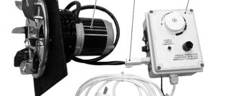
Kindling is carried out as follows:
- The air damper opens and the draft regulator is fixed in the raised position using a cable.
- Firewood is laid in layers. As a rule, large logs are placed in the center of the firebox, small ones at the edges.
- The top layer is filled with sawdust and wood chips. It will not be possible to add firewood until the already stored fuel has burned out, due to the internal structure and operating principle of the unit. Therefore, it is immediately necessary to fill the firebox completely (with the exception of the first kindling).
- The reason for the lack of draft may be the accumulation of soot in the smoke exhaust manifold, as well as insufficient heating of the chimney. Therefore, it is recommended to leave the damper open until the wood burns. This will provide good traction and reduce the formation of condensation.
Requirements for connecting the boiler to the heating system
GENERAL INFORMATION
The boiler must be installed by qualified specialists who provide guarantees for their work.
When installing additional elements, please read the manufacturers' requirements and follow them:
Following the recommendations of the thermal valve manufacturers, install the pre-flow control valves in accordance with the heating system design instructions.
Do not exceed the temperature of the flow into the heated floor using automatic floor heating elements (strictly follow the recommendations of the heated floor manufacturer, as a rule, the temperature recommended by the manufacturer is 28–35 °C).
To avoid bypassing the boiler and heating elements, install three-way or four-way valves and a circular pump in a large ring of the home heating system. Preferably on the return flow pipe.
Do not bypass the boiler and heating elements using a parallel connected boiler to the boiler (if the boiler is connected in parallel, be sure to use a balancing valve).
Maintain sufficient temperature for good boiler operation (65–85 °C). It is not allowed to install a damper to close the chimney. To reduce its traction, use a standard clamp. Make sure there is sufficient ventilation in the boiler room.
Every time you install a boiler, review the technical data sheet (useful additions or recommendations are possible).
For the correct operation and installation of Stropuva solid fuel boilers, regardless of the rated power, it is necessary to comply with the technical conditions:
To regulate the coolant flow passing through the boiler and simplify the boiler settings, it is necessary to install a balance valve with a flow meter before connecting the return circuit to the boiler. We recommend using balancing valve SRV-IG DN 25, BP 1″ Watts.
After setting on the valve passing through the technical. flow condition, when setting up the boiler, you only need to set the coolant supply temperature using the support bolt (2) on the bithermal draft regulator.
To light the boiler, as well as to increase the temperature of the return flow of coolant, it is necessary to mix the return flow with the supply coolant using a flow mixing unit (mechanical three-way valve, thermostatic three-way valve or hydraulic separator).
Is Stropuva good?
To the above disadvantages, of which the main one is slow heating (20 minutes for the boiler itself, but the whole system?), it is necessary to add the following:
- Impossibility of technological shutdown: the fuel load must burn out completely, only then can any work be done on the boiler and system.
- Impossibility of reloading fuel without re-ignition.
- The efficiency declared by the manufacturer (91.5%) does not correspond to both the values declared by dealers (85-87%) and the results of statistical processing of fuel consumption from real users, 76-78%
- A separate boiler room is required for the boiler according to the requirements of the Ministry of Emergency Situations (from 8 cubic meters, ceiling from 2.2 m, made of non-combustible materials, an openable window, an unobstructed supply window for air, a separate smoke duct).
Nevertheless, “Stropuva” is taken very willingly. The reasons are by no means marketing and advertising tricks:
Do-it-yourself piping of a solid fuel boiler
Tying a solid fuel boiler with your own hands is not a difficult task. If, of course, the hands grow from the right place. Every person who has bought a solid fuel boiler faces a problem: how to connect the boiler to the heating system. First thought: take a soldering iron for polypropylene pipes and tie the boiler. But you can’t do that!
Solid fuel boilers are tied only with metal.
And if you are a sensible person, you have a choice:
- buy factory boiler piping
- hire plumbers to plumb the boiler
- make the boiler piping yourself
Factory boiler piping
Many manufacturers of solid fuel boilers make piping for their boilers. The main disadvantage of such a harness is the high price. Or the complexity of factory wiring despite the simplicity of your system. We recommend that you think several times before buying a factory boiler piping.
Boiler piping done by plumbers
This is a good solution, if the plumbers are of course competent and can perform such work. Among the advantages, it is worth noting the design of the boiler piping, which best suits your heating system.
If you have the time and desire, then this is a great solution. You won’t need many tools to make the piping; in this article I will tell you how to make a boiler piping using two pipe wrenches or two adjustable pliers.
We have prepared a video instruction on how to piping a boiler, watch the video if you don’t like to read.
I should immediately note that using cast iron fittings is two, sometimes three times more profitable than brass ones. Therefore, if the goal is to reduce the cost of the piping, use cast iron fittings. In the video clip we showed how to make a piping for a solid fuel boiler yourself from scraps purchased at a hardware store. As an example, the piping was assembled on a long-burning STROPUVA boiler. But the principle of the piping scheme itself is suitable for any solid fuel boiler.
Top combustion boiler
In the post-Soviet space, these heat generators are known in two varieties:
- Baltic units (Stropuva) and their derivatives from other manufacturers.
- Wood-burning stoves of the “Bubafonya” type.
It is not known which of the heaters appeared first, but the Bubafonya stove has gained wide popularity as a heater for cottages, garages and other buildings with low requirements for the aesthetics of the product. The same cannot be said about top-burning boilers, although many for some reason consider them to be the only possible version of continuous-burning solid fuel heat generators. In fact, their only trump card is still the same - a large firebox.
The principle of operation of such boilers is to burn fuel, pressed down by a load, in a direction from top to bottom. Moreover, air is supplied to the combustion zone from above, through a telescopic pipe connected to the load. The operating diagram of the unit is shown in the figure:
Original boiler diagram, taken from the website stropuva.ru
During the operation of Stropuva boilers, many shortcomings appeared, as evidenced by reviews from owners on the forums:
- You cannot add logs to the firebox until the previous one has burned out. Physically this is possible, but then the principle of top combustion will be violated, the flame will engulf all layers of fuel.
- When working on fresh sawdust and other small debris, fuel residues “hang” on the walls.
- The efficiency of a TT boiler is not very high because it does not have a heat exchanger. Due to the air heating chamber and the large firebox, there was no room left for the heat exchanger.
The heat generator has no other critical shortcomings, and some things in the homemade version can be corrected according to your own understanding. For example, install a bottom and grates, organizing an ash chamber. You can also get rid of the problem with additional loading if you install an additional door between the loading and ash opening. This idea of upgrading a top combustion boiler belongs to another of our experts, Vladimir Sukhorukov, which he talks about in his video:
Preparation of materials
A round body creates some inconveniences in manufacturing, but you can’t make it square either - the fuel will “hang” in the corners. There is also a problem with assembling the telescopic pipe with a load, so it is better to take this part from the Bubafonya stove. A drawing of a long-burning boiler, comparable in size to the classic version, looks like this:
Before making a boiler, we select materials according to the drawing:
- pipe DN 400 with a wall of 5 mm - for the firebox;
- the same, DN 50 – for air supply and water pipes;
- the same, DN 100 – for the chimney;
- a round blank made of 10 mm thick sheet with a diameter of 38 cm;
- strip 40 x 4 mm – for air distributors;
- reinforcement with a diameter of 16-20 mm of a periodic profile - on grates;
- basalt wool 3 cm thick and density 100 kg/m³;
- thin sheet metal with polymer coating.
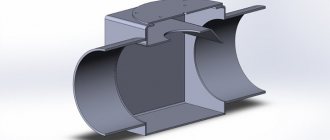
The choice of water jacket material depends on the method of its installation, because a home craftsman is unlikely to have rollers in stock that can give 3 mm thick metal a cylinder shape. The options are (shown in the diagram below):
- Scheme No. 1. Take a thin-walled pipe of larger diameter, although it is not easy to find one, and a regular one will make the boiler much heavier.
- Scheme No. 2. Bend two sheets of metal in 2 places at an angle of 60°, and then weld the two halves together. You will need a sheet press.
- Scheme No. 2 in a different design. Cook a shirt from 6 sheets - segments on clips.
- Scheme No. 3. Weld a rectangular box, which will increase the volume of the boiler tank.
Scheme No. 2 can be implemented in two ways - welded from 2 bent halves or 6 flat sheets.
You will also need 3 mm sheet metal for the frame of the doors, the bottom with a lid and the air damper.
Manufacturing of heat generator
The work begins with cutting out blanks and openings in the pipe wall according to the dimensions in the drawing. Doors are made from the cut out parts, and awnings and purchased handles are attached to them. The grate shown in the photo is made from the reinforcement:
In general, the algorithm for assembling a top combustion boiler looks like this:
- Cut a hole in a round blank for the load, insert a pipe into it and weld it.
- Weld 6 curved strips to the bottom of the load to serve as air distributors.
- Attach the bottom to the firebox and install grates inside.
- After cutting a hole in the center of the cover for the air pipe, attach it to the firebox. Before this, you need to put the pipe with the load in place.
- Weld the chimney pipe.
- Install the water jacket according to the chosen scheme, seal all joints.
- Make connections for coolant pipes.
- Perform insulation and casing of the boiler, install doors.
- Place a damper on the top of the air pipe.
Six distribution strips are sufficient to distribute air.
It is difficult to install automation and pressurization on a long-term top-burning boiler, since you cannot attach a fan to a moving pipe. It is necessary to make a flexible hose, and provide a submersible sleeve for the temperature sensor. It cannot be placed under the insulation, because the combustion zone in this type of heater is constantly moving downward.
It is better, of course, to test the boiler outside
Checking the serviceability of the sling boiler
Before using the boiler permanently, it is necessary to test its serviceability. This is necessary to ensure that the boiler can be operated in a safe manner in the future.
So, you will need to fill up to a third of the barrel of the device with firewood. It is covered with a lid on top, and before that you need to throw a match into the barrel so that the fire begins to flare up. For better ignition, be sure to add kerosene there.
Ideally, the wood should ignite immediately. There should be no draft, no smoke, no smell. If any of the above is observed, then you should not use such a boiler. It is highly likely to harm the owners of the house. However, if everything was done correctly, then there should not be such problems.
The specified amount of firewood is enough to heat a small room for a day. If the room is medium-sized, then it is worth doubling the amount of firewood.
Thus, the boiler is ready with your own hands. Perhaps today's option is not so successful for the home. However, it will be quite good for heating a garage or some non-residential premises. Let such a do-it-yourself device become a reliable source of heat for a garage or other room. Warmth and comfort for your home!