Industrial buildings, public institutions and residential buildings are equipped with complex air conditioning and ventilation networks. To organize the operation of a system that combines many technical devices, a ventilation control panel - SHCHUV - is used.
We will tell you how to assemble a shield that allows you to control the ventilation system and set the optimal mode for work or rest. The article we presented shows the components and describes the features of their connection. Taking our recommendations into account will help you competently automate the startup and shutdown of equipment.
What is automation for ventilation systems
Today, automatic ventilation control systems are represented by a large complex of various technical devices. All of them, from thermostats to complex computerized modules, are designed to facilitate the management and control of the operation of forced ventilation systems. The variety of equipment makes it possible to solve automation problems at any facility, regardless of its characteristics and purpose.
Based on operational and technical requirements, different approaches to the manufacture of automated ventilation control panels are possible:
- At some facilities, you can get by with standard modules produced in the form of cabinets with control devices installed in them.
- In other cases, installers have to manually assemble complexes adapted for complex supply and exhaust ventilation systems, taking into account specific tasks.
The difference in approaches is due to the need to ensure effective ventilation and create comfortable conditions for residents or workers in the interior of the building, regardless of the time of year and external weather conditions.
Important! In large shopping and entertainment complexes, in educational and administrative buildings, in large industries, the installation of equipment for automation of ventilation systems allows you to eliminate possible operational failures and minimize the influence of the human factor.
The operation of ventilation mechanisms is controlled using a set of sensors installed indoors. Some of them operate on the principle of a thermostat - as the temperature inside the building rises, fans automatically turn on, thereby ensuring a flow of fresh air.
Modern automated systems are equipped with elements of artificial intelligence and more complex instrumentation.
Structurally, similar modules consist of three groups of nodes:
- Sensors are devices that transmit information about the environment - thermostats, air humidity meters, gas analyzers. They transmit the collected data to the analyzing center.
- The control center collects and processes information coming from control sensors and, based on the analysis obtained, issues commands to control mechanisms to change the operating mode.
- Actuators are units that perform mechanical actions. This group includes: fan speed converter, servo drives for adjusting the position of valves, etc.
Control centers analyze the ratio of oxygen and carbon dioxide in the air, the percentage of humidity, and, if necessary, issue a command to ventilate the room. When a fire is detected, highly intelligent electronics independently block the flow of fresh air, preventing the spread of fire.
In normal mode, automation ensures the smooth functioning of all components and mechanisms of ventilation systems without the involvement of an operator.
Computerized modules transmit information about the operating mode and sensor readings to a single control panel. This allows the operator, if necessary, to adjust the operation of the automation and change settings remotely.
Note! Thanks to the use of automation, a much smaller number of technical specialists can control the operation and maintain ventilation with installed automation.
Depending on the specific situation, one of 3 device control modes is used:
- Manual. Ventilation control is carried out by an operator located directly in the control room or at a remote control panel.
- Autonomous. The equipment operates in accordance with the established settings, regardless of other engineering systems installed in the building.
- Auto. Control devices are integrated into the overall control of all engineering complexes of the building. The ventilation operation is synchronized with other devices and sensors located in the house - for example, with a fire alarm and other emergency sensors.
Thus, the automated complex plays the role of a control center. It starts the ventilation, stops it, processes sensor readings and sets the desired mode depending on temperature, humidity and other parameters.
Advice from professionals
The efficiency and trouble-free operation of a ventilation unit or hood largely depend on the correct choice of control cabinet
Therefore, it is better to entrust the purchase of such an important and technically complex unit to professionals. Before purchasing a cabinet, the master will carry out full monitoring of all components of the ventilation system and decide on the contents of the cabinet
After selecting the configuration, the specialist will test the installation and determine the maximum possible load on a particular device and on the network as a whole. Based on the data received, the wizard will select the optimal connection diagram, determine the operating mode of all devices in order to increase their efficiency, and only after that will specifically indicate the necessary equipment.
When choosing equipment yourself, you need to focus on the current strength in the circuit, the power of the units and the size of the wire cross-section. This is due to the fact that if the wire and current strength do not match, severe overheating of the terminals and contacts occurs, which can lead to breakdown and even fire of the equipment. When purchasing and connecting a cabinet yourself, you need to remember that for each square millimeter of copper wire there should not be more than 10 amperes, and connecting terminals, one of which is made of copper and the other of aluminum, is unacceptable. This can lead to a galvanic effect and weaken the contact.
To learn how to install a simple ventilation control cabinet, see the following video.
Purpose of the ventilation control panel
If it is necessary to turn on or configure a household split system or supply ventilation devices fixed in the ventilation duct opening, then no control units are required - each device is adjusted manually or from the remote control.
But if the length of the networks is large, and the devices are installed in inaccessible places: in shafts, on the roof or attic, in specially designed niches inside the walls, then it becomes necessary to install a remote control unit.
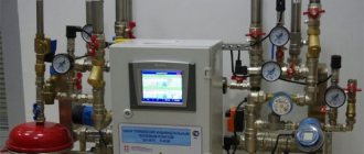
All information about the operation of air heaters, convectors, and individual fans goes to a single center - SHCHUV. Automatic machines responsible for the operation and adjustment of devices are also located here.
Modern control panels are panels with indicator control devices or metal cabinets that are installed on the floor or suspended from the wall. To protect the internal contents, there are hinged doors that can be locked. In addition to the abbreviation SHUV, you can also find SHUV (cabinet).
Main functions of the SHCHUV:
- control over equipment included in ventilation and air conditioning systems;
- protection of units from overheating, incorrect installation and connection, short circuit;
- adjustment of the most important equipment parameters, such as productivity or power;
- programming the operation of the entire system or individual units for a given time period - day, week, month;
- providing an indication that facilitates monitoring and adjustment;
- maintaining a certain temperature in various rooms, the ability to quickly change its parameters;
- control over the internal walls of air ducts and the degree of filter contamination;
- preventing failures in the operation of seasonally dependent equipment, for example, water heaters, which can freeze at too low temperatures.
Installing an electrical panel at an enterprise or in a residential building allows maintenance personnel to monitor the operation of equipment from one place and quickly respond to breakdowns and shutdowns of individual devices. Devices that control fire extinguishing and partial heating devices can also be located in the same cabinet.
SHUPVV installation diagram. Cabinets can be common, combining all the devices in the building, and serving a separate floor, wing, workshop, section, etc.
If an emergency occurs, for example, a fire in one of the rooms, the ventilation equipment is stopped automatically or manually - from the control panel.
Which power actuators do not require integrity monitoring.
1. Intermediate relay.
Relays must consume minimal power and switch maximum voltage. That is, it is best to use an electronic relay.
In turn, the relay controls something.
There are 220V intermediate electronic relays, the operating current of which is up to 0.25A and therefore they can be controlled by switching power with low-current addressable relay modules “Rubezh”.
The intermediate relay PK-1P costs 680 rubles, switches 16A 220V and consumes 0.05A when 220V is activated.
This is what I understand as a relay amplifier!
2. Independent release.
The fire alarm energizes the release and the release switches off the circuit breaker.
But how can a fire alarm send a 220V signal to the release?
Using any relay capable of switching 220V.
But it is worth remembering that an independent release is a device that performs mechanical work and its current consumption is greater than that of the relay coils.
Here are the control signal parameters for the most common S2C-A independent releases.
We see that the operation current of S2C-A2 at 230V is 1A. That is, weak relays of low-current relay modules are not suitable for all.
It is tempting to control the low-current independent release S2C-A1, whose response voltage is 12..60V.
But the response current... for 12V is 2.2A. It is doubtful that the response current for 24V 4.5A is greater than for 12V, although it should be less.
Triggering such a release using the S2000-KPB will be on the verge of a foul, since the maximum switching current of the unit is 2.5A. Switching current “S2000-SP2 ISP.02” is 3A.
It is reassuring that the operating time of the release is 10ms.
An independent release is a good control method if additional attention is required to start a complex ventilation system: the ventilation system will not start simply after the alarm is removed. To turn on the system, you need to walk with your feet to the circuit breaker that is turned off by the release.
To turn on the system, you need to walk with your feet to the circuit breaker that is turned off by the release.
But there is one interesting point. Let me quote from the regulatory framework:
SP 60.13330.2012 Heating, ventilation and air conditioning. Updated version of SNiP 41-01-2003
12.3 For buildings and premises equipped with automatic fire extinguishing installations or automatic fire alarms, automatic blocking of electrical receivers of air heating, ventilation, air conditioning systems, autonomous and window air conditioners, fan coils, air-heat curtains and internal air conditioning units (hereinafter referred to as ventilation systems) should be provided. , as well as electrical receivers of smoke ventilation systems with these installations (or fire alarms) for:
a) shutting down ventilation systems in the event of a fire, except for the air supply systems to airlocks of premises of categories A and B, as well as to the machine rooms of elevators in buildings of categories A and B. Shutdown can be carried out:
centrally, stopping the power supply to the distribution boards of ventilation systems;
individually for each system.
When using equipment and automation equipment supplied complete with ventilation system equipment, shutdown of supply systems in case of fire should be done individually for each system while maintaining power supply to the frost protection circuits. If it is impossible to maintain power to the frost protection circuits, it is permissible to turn off only the fan by sending a signal from the fire alarm system to the remote control circuit of the supply system fan. When organizing a shutdown in case of fire using a circuit breaker with an independent release, the signal transmission line must be checked for shutdown.
The highlighted phrase about checking the signal transmission line contains a big problem. The independent release will most likely be 220V! And we have the problem of continuous monitoring of the integrity of the 220V control circuit.
3. Contactor (starter).
The dry contacts of the relay open the self-retaining circuit of the magnetic starter.
The advantage of this approach is that when relieving an alarm, you don’t have to go to the control panels.
So, for example, it makes sense to control the fire-retarding valves of the OZK: the alarm was removed - the OZK opened on its own.
The current on the PME 211 coil is only 0.1A. But still, the use of a low-current addressable relay module for some addressable systems is questionable, since this is a continuous current.
The main tasks of automation for ventilation
Since the modern market offers a large number of various technical devices for ventilation automation, the range of their functions is also extremely wide.
Main functions of the control module equipped with elements of electronic intelligence:
- Maintaining the specified parameters of the microclimate of the interior - air temperature and humidity, carbon dioxide saturation, etc.
- Possibility for the operator to remotely control the fans, turn them on and off remotely.
- Implementation of automated control over the sensors of all components and assemblies of ventilation equipment.
- Independent transfer of equipment to summer or winter mode.
- Monitoring the level of contamination of filter devices with the function of signaling the need for cleaning.
- Opening and closing air duct dampers, adjusting the performance of supply and exhaust fans.
- Cutting off the fresh air supply when the fire alarm is activated.
- Turning off the power supply in emergency situations - sudden surges or drops in voltage. This allows you to prevent failure of devices, sensors and individual components of the ventilation system.
Note! The exact list of functions that a particular automated module is equipped with should be obtained from the seller or manufacturer.
Additional functions
Modern manufacturers, in order to fully satisfy customer requests, pay special attention not only to the reliability of the equipment they produce. An important factor in the competition for consumers is equipping products with as much additional functionality as possible.
Today, highly intelligent functions such as:
- Connecting ventilation to a single electronic “smart home” control controller.
- Manage settings via Internet applications, using Wi-Fi and Bluetooth.
Equipped with modern functionality, automatic equipment becomes clear and easy to operate, like other household appliances.
General information
Ventilation control system is designed to monitor and control supply and supply and exhaust ventilation systems of buildings with a different set of equipment, which may include: recuperator, cooler, heater, control valves and pumps in the cooler and heater circuit, air dampers, filters.
Problems solved during the implementation of automatic control systems:
- automatic maintenance of the set temperature and air exchange rate in the serviced room;
- ensuring fire safety - controlling fire-retarding valves;
- timely diagnosis of ventilation equipment failures.
- maintaining the air temperature in the serviced premises within the limits specified by the controller program;
- continuous automatic protection of the water heat exchanger from freezing based on water temperature and supply air temperature, monitoring air filter contamination in the supply system;
- operation of ventilation systems in the “Day”/“Night” and “Winter”/“Summer” modes;
- monitoring the condition of controlled equipment.
The ventilation ACS exchanges information with the dispatch console, providing the following capabilities:
- transmission of technological parameters, messages about emergency situations and data on the operation of actuators to the control panel;
- remote control for individual mechanisms if necessary, while maintaining automatic control for the system as a whole, and incorrect operator actions are blocked;
- receiving commands from the dispatch console for unscheduled switching on and off, as well as temperature assignments in the serviced premises.
In addition to the main control mode from the dispatch console, it is possible to control ventilation systems locally from push-button control stations (CPC) located in the serviced premises.
The ACS hardware and software platform provides high configuration and programming flexibility. As a result, the following characteristics of the self-propelled gun are provided, distinguishing it from similar products:
- the ability to connect small ventilation systems to controllers of large ventilation systems without installing additional control cabinets;
- the ability to connect actuators of other engineering systems (fireproof valves, smoke removal fans, water pumping stations, etc.) to the controllers of ventilation units;
- the ability to implement modifications to the controller and control programs in a short time and at low cost in the event of changes in the original project for automation of engineering systems;
- flexibility of control algorithms, which allows them to be easily modified during the design of engineering systems if appropriate customer requirements arise;
- the ability to transfer information to the upper level using any standard protocols required by the dispatch system supplier.
Features of the SHCHUV device
Installation and configuration of control panels is carried out according to the rules and regulations dictated by government documents, such as GOST R 51321.1. Cabinets for pumps and electrics, panels for ventilation and air conditioning systems are mounted in corridors, utility rooms or in specially designated rooms - switchboards.
If the building has the capabilities, then all control units, including ventilation and fire protection, are installed in control rooms.
In the room where the switchboard is located, room temperature and normal humidity levels must be maintained. All devices must be protected from direct UV rays and dust, as well as from magnetic vibrations and radio interference
Manufacturers of electrical equipment offer a variety of configurations that vary in size, functionality, degree of protection and level of programming. The simplest modifications are intended for servicing private residential real estate, while complex modifications are intended for enterprises and public buildings.
Requirements for the configuration of control panels
When choosing a SHUV, they are guided by the size of the working area, the ability to install the necessary devices, ergonomics and safety. The last point applies both to the installers themselves, who regularly service the networks, and to people who may be nearby.
The main requirements for SHUV and SHUV are as follows:
- the panel must accommodate all control devices for the ventilation and air conditioning system;
- important components must be equipped with an indication, light, digital or connected to a PC;
- devices responsible for the most important equipment must have dual control - automatic and manual.
All devices are neatly placed on the same plane. The package should be as simple and easy to understand as possible. If the ventilation panel is assembled according to all the rules, then, if necessary, even a person ignorant of electricity will be able to turn off emergency devices.
Modern control units are manufactured taking into account the possibility of saving energy. Let’s assume that properly selected automatic devices can reduce costs by 50-65%
The content and functionality of the shields may vary. For example, some systems require a frequency converter, while others do without it. The most convenient for use are cabinets and panels with automation and remote controls.
Work Item Overview
Structurally, the SHUV is a rectangular plastic or metal case with the required protection class IP 45. If operating conditions are associated with an increased risk, then the protection class is higher.
Inside the case there are devices such as a power supply, controller, and converters. Several circuit breakers are responsible for individual devices: air heaters, recuperators, fans, cooling units, etc.
A mandatory element is a manual control panel. An alarm unit is also required, which is triggered in an emergency and produces warnings with light or sound signals.
Strips and terminal blocks for installing electrical devices and connecting them with wires look the same as analogues for electrical distribution boards
Control elements also include sensors. These are a kind of receptors that collect various information about the state of the system and its environment.
They measure the temperature of the air and the devices themselves, the degree of concentration of gases or contamination of system elements, measure the speed of air movement, etc. The data obtained is sent to automatic regulators, and the operation of the system elements is adjusted.
Based on their functions, sensors are divided into the following types:
- temperature;
- humidity;
- speed;
- pressure, etc.
Temperatures can be either digital or analogue. A signal about a sharp increase or decrease in indoor temperature may cause the system to switch to another mode.
Humidity sensors operate on the same principle. The movement of air masses inside ventilation ducts can be determined using speed and pressure sensors. Based on their installation location, sensors are divided into internal and external. The first ones take data indoors, the second ones, which are also called atmospheric or street data, take data from outside buildings.
Ventilation sensors can also be ducted, that is, installed inside air ducts: either on the walls or across the air flow. They are universal and can transmit a large amount of information: temperature, pressure, air speed
Some sensors are fixed on the surface of parts that need to be monitored. They take parameters of the devices themselves, for example, winding temperature, rotation speed, etc.
The installation of sensors requires careful selection. On the one hand, the more information, the more accurately the system operates, but on the other hand, the operation and maintenance of the network becomes costly in terms of energy consumption.
Controllers work in conjunction with sensors. These are the devices that receive information and process it automatically. They can be called intermediaries, since the signal is then transmitted to actuators: air flow switches, fans, refrigeration units, heaters.
Controllers with microprocessors are more suitable for installation inside SHUV. They are compact in size and do not require a large area for installation
Particularly popular are universal type controllers, which are capable of simultaneously processing information coming from various systems: ventilation, heating, etc.
Recommendations for assembling SHUV
Installation and testing of control panels should be carried out by specialists with appropriate qualifications; independently installing and connecting elements inside a switchboard or cabinet is not only not recommended, but also prohibited.
The housings are not made by hand, but purchased ready-made or ordered taking into account the specifics of the ventilation system. A set of devices is supplied with the case: switches, controllers, power supplies, switches, protection elements and wires.
It often happens that the set of instruments and parts is not fully equipped - there are not enough wires or circuit breakers. When selecting spare parts, it is necessary to maintain compliance with the technical characteristics (for example, the cross-section of wires or the current strength of the machine).
The set of SHCHUV elements is accompanied by a diagram according to which the assembly is carried out. Any deviations from the diagram may lead to improper operation or equipment breakdown.
Before ordering, you must make a list of all devices that are included in the ventilation system, as well as express your wishes regarding switching operating modes, the type of controller, and the presence of certain sensors. In some control panels, relays are installed instead of controllers.
An example of a ShchUV can be a sample with the following technical characteristics:
- nom. frequency – 50 Hz;
- voltage – 380 V;
- voltage of the connected fan – 220 V;
- engine power – 22 kW;
- protection level – IP65;
- dimensions – 400x800x180 mm;
- service life – 10 years.
Ready-made models are marked with symbols that contain information about the modification and its standard size, degree of protection, type of climatic modification, technical specifications or GOST number. In the latter case, manufacturers are guided by GOST 14254 and GOST 15150.
Automation functions and capabilities
The automation of the ventilation system performs several important tasks. Let's get to know them.
- Thanks to automation, the entire system works properly and is always under control. Usually a special accident analyzer is installed. Modern developments make it possible to control automatic systems remotely - the operator only monitors the operation of the existing device, and can also make his own adjustments by setting certain modes.
- Using automatic equipment, it is possible to analyze individually and monitor the functioning of each existing mechanism. In addition, it is possible to monitor the overall activity of the ventilation circuit. The unit’s sensors provide certain data, the automatic system examines the position and makes its own adjustments to the operation of the equipment. If an accident occurs, a corresponding shutdown signal is sent to a special start button.
- Automation in ventilation systems is also designed to save valves and water heating circuits from the harmful effects of low temperature values. In addition, automatic equipment prevents the temperature from dropping to dangerous levels.
- The automatic control system allows you to regulate the ventilation in the room. Thanks to this addition, it is possible to switch various modes. Thus, in conditions of sudden changes in loads and temperatures, automation can reduce the rotation speed of existing fans, as well as deactivate the equipment completely.
- If there is such a nuisance as a short circuit or other similar problems, then the automation simply blocks certain mechanisms to prevent fire and electric shock to people.
As you can see, the automation that comes with the ventilation system performs many functions and allows you to avoid many serious problems. In addition, it is much easier to regulate ventilation with automatic components.
Model overview
SHUPN-2
Typical cabinet for controlling two pumps (including standby). Used to interact with submersible units used in fire extinguishing and agricultural irrigation systems. Power up to 55 kW, operating temperature from -10 to +50 degrees. The manufacturer sets special requirements for the environment. The air should not contain aggressive gases and not be saturated with conductive dust. Relative humidity up to 80% is acceptable. The cabinet is designed for a service life of ten years. Retail price 31,600 rubles.
SCHOON
Produced, representing the product on the domestic market since 2005. The equipment warranty is two years.
The cabinets are designed to work with drainage pumps and sewage pumping stations. Can control fire tanks. The unit is controlled in two modes - automatic and manual.
You can connect two pumps - backup and main. If the main pump fails, the backup pump will be activated automatically. Automatic alternation of pumps is provided to ensure uniform operating time and prevent winding overheating. At the request of the customer, the unit is modernized. For example, a GPRS module is installed, which ensures the forwarding of SMS messages in the event of an emergency. The permissible power of each pump is from 4 to 11 kW, depending on the cabinet model. The average cost of a budget model is from 10,900 rubles.
SHKANS-0055
If you are the owner of a country house or cottage with an autonomous water supply, then you have probably at least once wondered how to make pumping equipment work more efficiently and longer, and also have several convenient operating modes. In addition, sometimes two pumps are used at once to provide the house with water and water the garden, so it is necessary to coordinate and automate their operation. You will get the answer to all your questions when you find out what a pump control cabinet is and why it is needed.
The main purpose of distribution cabinets is to control the electric motor of one or several pumping units at once. In this case, the type of pump does not matter. This can be submersible equipment or a well or drainage pump.
Moreover, the purpose of pumping equipment may be different. For example, a submersible type unit is needed for the efficient operation of a heating system, arranging the water supply of a country house, or creating a fire extinguishing system. But the drainage pump, together with the control cabinet, is useful for pumping liquid.
If you install a control cabinet to coordinate the operation of the well pump, you will finally find long-awaited peace and relaxation, since from now on you do not need to monitor the operation of the equipment, all this will be done by the automation located in the cabinet. In this case, this device will be able to perform the following functions:
the equipment will ensure safe and smooth starting of the pump unit engine; automation will be able to regulate the operation of the frequency converter; in addition, the device will monitor the pressure in the system, the water level, as well as its temperature, which is very important for the timely switching on and off of pumping equipment.
The functions of control cabinets for two or more pumps are even more extensive:
- if the unit notices that one of the pumps is operating in emergency mode, it will immediately connect the second pump to operation;
- since the automation of the control cabinet will regulate the alternating operation of each pump, the overall wear and tear of the pumping units will occur later;
- if one of the pumps is left idle for a long time, the equipment will be able to protect it from silting;
- Thanks to this device, you can manually block the operation of one of the pumps;
- cabinet automation has different programs for controlling several pumps;
- if necessary, you can obtain complete data on the operation of each unit separately.
Sensors and Transducers
Sensors are elements of ventilation automation systems that serve to obtain information about the real state of the controlled object. With their help, feedback is provided between the control system and the object according to the following parameters: temperature, pressure, humidity, etc.
In order for information from the sensor to be transmitted to the system in the form of a digital code, each sensor is equipped with a converter.
The optimal locations for installing the sensors are indicated in the instructions supplied with them.
Temperature sensors can be for indoor or outdoor use; overhead on the pipeline (for monitoring the surface temperature of the pipeline) or duct (for measuring the air temperature in the air duct). Indoors, temperature sensors are installed in neutral places relative to sources of heat or cold, outside the building in places where the sensor will be protected from wind or direct sunlight.
Humidity sensors are a unit with an electronic device that measures relative humidity and converts the data into an electronic signal. There are external and internal versions. They are installed in places with stable humidity conditions; they are not allowed to be installed near heating radiators, air conditioning units, or near sources of moisture.
Pressure sensors are divided into pressure switches (mechanical measurement of differential pressure and electrical conversion) and analog pressure sensors (conversion of pressure directly into an electrical signal, for example, using piezo elements). Both are used to measure pressure at one point and the difference in pressure at two points.
It is advisable to install both external and internal sensors in twos or more, for example, on the north and south sides of the building. In modern systems, all external climate sensors are combined into a single weather station.
Flow sensors measure the speed of a liquid or gas in a pipeline or duct. Liquid flow is calculated using a formula inside the processor unit based on the pressure difference and other parameters (temperature, pipeline cross-section, density).
Accessories
The fan control cabinet is equipped with a power supply, controllers, converters and a large number of on/off switches. The switches, in turn, are connected to electric heaters, heat recovery devices, fans, water heaters and refrigeration units. A mandatory element of the switchboard is a manual control unit, which assumes the functions of regulation and control in the event of a failure or malfunction of the automation. In addition, all cabinets are equipped with emergency alarm sensors that are triggered in the event of an emergency or pre-emergency situation.
A special role in monitoring the operation of ventilation systems is played by sensors, which are a kind of receptors and collect information about the performance of each node. With their help, you can get a clear picture of the pollution of air flows, their temperature and humidity, as well as the speed of movement of air masses and the speed of rotation of the fan blades. Temperature sensors are available in both digital and analogue versions, and when the temperature inside the system changes, they help switch the entire installation to another mode. Humidity sensors work on the same principle. The information received by the sensors is sent to automatic regulators, which, in turn, adjust the operation of key components of ventilation systems.
Based on their location, sensors are divided into external and internal. The first ones are often called atmospheric and are installed on the outside of buildings. Internal ones, in turn, are divided into channel and surface models. Ducts are installed inside air ducts on the walls or across the movement of air masses. Surface ones are placed on the surface of the nodes and remove parameters from these devices.
An equally important element of control cabinets are controllers. The devices receive information coming from sensors and process it automatically. After processing the parameters, the controllers send a signal to the main units of ventilation units, such as fans, heaters, refrigeration units, after which they change their operating mode. Functionally, the controller can either serve several devices or interact with only one of them. Universal models are often equipped with microprocessors, which makes them less bulky and can be easily placed in a small cabinet or stand.
Another element of the shield configuration is fan blade speed converters. Thanks to these devices, it is possible to regulate the number of engine revolutions, thereby significantly reducing the amount of electricity consumed by the installation. In addition to saving money, this leads to a significant reduction in wear on fan parts and extends the overall service life of the ventilation unit.
Regulators
Regulators are one of the main elements of an automation system for ventilation, providing control of actuators based on the readings of various sensors.
According to their functional purpose, these elements of ventilation systems are divided into speed regulators and temperature regulators.
Speed controllers can be single-phase or three-phase (just like motors). They also come with smooth or step control, and the choice of control method depends on the power of the fans. The most modern and economical method is to speed up the rotation of pumps and fans using frequency converters (FCs). Despite their high cost, inverters are economically justified even on motors with a power of more than 1 kW.
Temperature regulators, depending on the control method, are threshold ones, controlling the temperature using a fully open or fully closed damper (for example, a car thermostat), and with proportional differential control (PID), allowing smooth control of the temperature in the operating range.
Regulators in ventilation automation systems are controlled from control panels.
Popular models
The following brands have proven themselves very well on the domestic market:
- The range of Grundfos brand cabinets is quite extensive. It contains products with different configurations and technical characteristics. Some models have protection against dry running, low voltage and phase failure. However, they all can:
- manage pumping equipment;
- automatically start the unit after a long period of inactivity;
- control the water level and display data on the display panel;
- regulate the operation of equipment;
- such products can be used in the temperature range from -20 to +40°C;
- All equipment of this brand comes with a two-year warranty.
- Alpha Control brand cabinets reliably protect pumping equipment from negative factors that cause units to fail. They can work with any pump models. These products are designed for connection to a 220 and 380 V network. The “D” marking in the designation will indicate that the model can be used to control two pumps.
Automation boards
The operation of the automated system, its convenience, reliability and safety of operation directly depend on the process control algorithms (specialists who performed the design and commissioning), as well as on the capabilities of the components. Algorithms are implemented at the software level and “hardwired” into freely programmable controllers installed in automation panels .
When connecting sensors to the automation panel, the type of signal transmitted by the converter (analog, discrete or threshold) is taken into account. Expansion modules that control device drives are selected in the same way.
Ventilation system panels can be power, control or combined if the system is small.
Automation panels for ventilation provide:
- Turning the ventilation system on and off;
- Equipment status indication;
- Protection against incorrect connection of supply voltage and short circuit;
- Ventilation unit performance control;
- Indication of the status of air filters;
- Protection against overheating of electric motors;
- Protection of the air heater from freezing;
- Maintaining and controlling the air temperature at the inlet of the ventilation unit and in the room;
- Possibility of using temporary manual control algorithms.
Description of the functional diagram
The functional diagram shows the principle of automated control of supply and exhaust ventilation, drawing DP AT061 K897 E2.
During operation of the system, outside air enters the air supply unit through the air intake grille, passes through the open air valve, and then passes through the silencer into the pocket filter section. After this, the purified air passes through the heating section and is heated to a temperature of 22°C during winter operation. The air then passes through the cooling chamber and is cooled during summer operation. Then the air enters the fan section, where pressure is created and, after the silencer section, it enters the serviced premises through air ducts.
The supply air temperature is measured by sensor (16a). The measured temperature is transmitted to the control panel, and the controller generates a signal to the shut-off and control valves (8a, 11a).
The system provides filter clogging monitoring. When the pressure difference before and after the filter exceeds 100 Pa, the sensor (4a) will close its contacts and this signal will turn on the light alarm and if the filter is not cleaned or replaced within 72 hours, it will stop the system.
The system provides protection for heaters from freezing. When the water temperature in the return pipeline drops below 20°C, a signal from the sensor (5a) is sent to the control panel. Protection for air temperature after the heater is also provided. Sensor (9a) will generate a signal at a temperature of 5°C which will be sent to the control panel. When one of the signals is received, the fan stops, the external air valve interlocked with it closes and the three-way valve (8a) fully opens to maximize the coolant flow. Thus, the movement of cold air stops, and the circulation of coolant through the heater continues. Due to the lack of heat removal, the temperature of the cooled coolant begins to rise. When the coolant temperature reaches 50°C, the fan turns on, the outside air valve opens, and the operation of the air heater resumes.
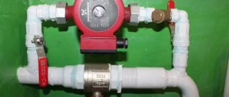
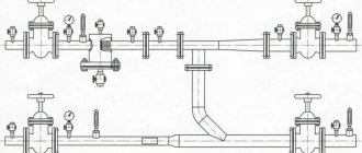
The outside air temperature sensor (1a) switches between winter and summer operating modes. Depending on the operating mode, the air is either heated or cooled. To regulate the temperature of the supply air, a control unit for the supply of coolant to the air heater is used. The diagram of the control unit УУ1 is shown in Figure 3.
Figure 3 - Diagram of the control unit УУ1.
- 1 — Surface-mounted thermostat to protect the heater from freezing in water.
- 2 - Circulation pump.
- 3 - Indicating dial pressure gauge.
- 4 - Indicating dial thermometer.
- 5 - Filter.
- 6 — Surface-mounted return water temperature sensor.
- 7 - Balancing valve.
- 8 - Shut-off ball valve.
- 9 — Three-way valve with electric drive.
Water from the heating network passes through a balancing valve and filter and enters the heat exchanger, gives off some of the heat and returns to the heating network. The circulation pump mixes supply water with return water, which enters the supply pipeline depending on the position of the control valve. The control valve increases or decreases the flow of return water into the heat exchanger depending on the supply air temperature or the return water temperature, which is measured by a clamp-on temperature sensor. An overhead thermostat protects the heat exchanger from freezing of the coolant. If the water temperature is below 0°C, the coolant will freeze and lead to rupture of the heat exchanger tubes, which cannot be repaired and is expensive to replace.
In the summer operating mode, the coolant supply control unit is used to control the coolant supply to the air cooler. The control unit for the supply of coolant to the air cooler UU2 is shown in Figure 4.
Figure 4 — Coolant supply to air cooler УУ2.
- 2 - Circulation pump.
- 3 - Indicating dial pressure gauge.
- 4 - Indicating dial thermometer.
- 5 - Filter.
- 7 - Balancing valve.
- 8 - Shut-off ball valve.
- 9 — Three-way valve with electric drive.
Water from the refrigeration machine passes through the balancing valve and filter and enters the cooling section, is heated and returned to the heating network. The circulation pump mixes supply water with return water, which enters the supply pipeline depending on the position of the control valve. The control valve increases or decreases the flow of return water into the heat exchanger depending on the supply air temperature.
How to choose and install
When choosing control equipment for ventilation devices, special attention should be paid to the operational and technical characteristics.
An important role in the correct selection of equipment is played by the complexity of the ventilation duct system, the number of rooms and their internal volumes, as well as the number of people in the room.
Preference should be given to products from companies that have proven themselves in the electronics market.
It is important to find out what the warranty obligations are and whether free service is provided. The higher the quality level of the equipment, the higher its cost. However, you should not spare money on high-quality equipment, since it will recoup all costs with many years of trouble-free service. The ideal option would be to find an electronic control module that combines build quality, a large number of functions and an affordable price. As practice shows, such equipment is now found among the products of new companies just entering the world market.
It is important! Installation and connection of ventilation automation systems should only be carried out by technicians with special approvals.
Specialists who have undergone the necessary training install the equipment in full compliance with the requirements of technical regulations.
When connecting independently, errors are possible that can lead to failure of both individual components and the entire equipment. Also, self-installed control systems are not subject to service, and in the event of a breakdown, the buyer will have to repair them at his own expense.
Manufacturing materials
When designing the design of venous system equipment, the operating conditions in which they will function uninterruptedly are taken into account. Cabinet interiors are rarely installed outside the panel.
When developing a project, the following are taken into account:
- ambient temperature during operation. If the temperature regime is not observed, the performance characteristics will deteriorate. The material will quickly melt, wear out, and the power equipment located inside will become unusable;
- the humidity regime must also be ensured within standard values so that short circuits do not occur on electrical parts;
- providing altitude relative to sea level. This indicator affects the forced ventilation device, since heat exchange conditions worsen when atmospheric pressure parameters change.
When installing equipment, the environment inside the cabinet, compared to the outside air, changes. Based on the results of the research, cabinets for equipping ventilation systems with opening lids are produced. But they often use the current climate control standards for the corresponding external operating parameters, while taking into account:
- working temperature;
- temperature indicators inside the cabinet and outside the technical device;
- indicator of the radiated power of the equipment;
- specified altitude above the level of the Baltic Sea.
When choosing a material, you should take into account the dimensions of the designed cabinet, the type of installation, and then select one of the existing materials, set the height relative to sea level, taking into account the environmental indicators and the design power, which exceeds the nominal by 5%.
Installation of ventilation systems
Before installing ventilation systems with automatic components, proper design planning is required. To do this, you need to have certain engineering skills, so it is best to entrust such work to professionals.
Current technologies make it possible to design quite complex automatic control systems for ventilation systems. For this reason, their installation and subsequent commissioning, even with a well-designed project, should only be carried out by experienced specialists. It is not recommended to carry out such work with your own hands, especially if we are talking about a very complex scheme. Any shortcomings and errors made during installation can provoke a serious disruption of air exchange, which will result in conditions in the existing space that are impossible for people to stay in.
An equally important stage in carrying out such work will be commissioning. At this point, the operation of the assembled ventilation system as a whole is checked, and all the necessary indicators are provided in accordance with the project developed in advance.
As a result, proper operation of ventilation will contribute to the formation of a comfortable microclimate in the existing room or designated area. The use of modern technical devices provides many advantages, guaranteeing faster execution of the required commands.
Exhaust unit operating modes
Installation Modes Screen
M1 – auto/off – Fan 1 – on – off
M2 – auto/off – Fan 2 – on – off
If we first turn on switch SA1 in the auto, then fan M1 becomes the main one. When switch SA2 is turned on in auto, fan M2 becomes a backup fan. If we turn on SA2 first, then the main fan will be M2, and M1 will be the backup. If one of the fans fails, the system automatically switches to the backup one.
Accident. Stopping the system
This mode is activated when a fire alarm is triggered, the outside air damper is faulty, or the inlet temperature sensor is faulty.
Setup
In the setup mode, you can turn on all mechanisms separately. When this mode is enabled, the green indicator on the PLC lights up.
Hood settings screen
Setpoint. Honored Vozd St. — The setting for the street air damper MAM3 is the setting for the PID controller to regulate the damper according to the inlet temperature sensor.
Setting T min – setting the minimum temperature according to the temperature sensor
Setting Tmax – setting the maximum temperature according to the temperature sensor
When the Tmin and Tmax settings are exceeded, it goes into Emergency mode. System stop.
Dead zone MAM3 – Dead zone of the MAM3 damper. The MAM3 outdoor air damper is always controlled. We submit the task\receive a return signal. The dead zone is the zone in which the damper has no sensitivity. You can set it to 2-5 degrees.
Prop. coefficient (МАМ3) – proportionality coefficient of the PID controller
Integral coefficient I (MAM3) – integration coefficient of the PID controller
Proportionality and integration coefficients are coefficients for the PID controller of the street damper. Selected empirically.
Setting min M1 – Minimum fan control range M1
Setting max M1 – Maximum control range of fan M1
Setting min M2 - Minimum fan control range M2
Setting max M2 – Maximum fan control range M2
Fans M1 and M2 operate directly proportional to the damper PID output. The min and max settings set the fan control range. (min- 15, max- 1015). That is. 15 - 0 hertz, 1015 - 50 hertz.
Setting Motor hour M1, Setting Motor hour M2 – set the time in hours after which the main fan will turn off and the backup fan will start working.
Hood parameters screen
The screen displays various installation parameters - the position of the street air damper, the state of the hood M1 and M2, the position of the dampers MAM1 and MAM2, the operating time of the fans M1 and M2.
Screen Filters
Filters – response delay. The response delay in seconds is set for a particular accident, or for turning on fans or dampers.
Resetting system alarms - switches SA1 and SA2 are set to off. Press the F1 button on the PLC.
Setup and management
Newly installed ventilation systems must be properly configured. Of course, the correct distribution of air flows must be taken into account at the project development stage, when a number of required engineering calculations are carried out. However, in this case it is important to consider that:
- when designing, standard-type air duct sections are more often used, and the air itself can flow through them at different speeds;
- The lion's share of schemes have certain areas where it is possible to correctly distribute the air only manually.
Taking into account these features, we can conclude that it is also better to entrust the installation of a ventilation system with automation to specialists. The procedure for carrying out this work is as follows:
- first, using an anemometer, the average speed of air passage through the ventilation grille is determined and calculated;
- then, using the value of the open cross-section of the grille, the volume of air is calculated based on a special formula;
- with the help of a control valve, the volume of air entering the grille decreases or increases;
- the air flow valve is built into both the air outlet and the grille;
- having changed the angle of the control valve flap, again carry out all the required measurements of the speed of air masses on the grilles;
- all identified parameters are checked against the project, and in case of discrepancies, the system is adjusted further.
The main control capabilities of a properly installed ventilation system with automation are:
- sequential start;
- sequential stop;
- reservation and addition.
Advantages
- Creation of a full-fledged supervisory control and management system with the ability to continuously monitor the operation of the ventilation system
- Timely provision of high-quality information to operational personnel about the progress of the technological process, the condition of engineering equipment and technical controls
- Reducing the likelihood of operator errors due to timely presentation of information in a visual form
- Increasing the operational life of ventilation equipment due to immediate response to system failures
- Reducing energy consumption through the implementation of automatic regulation and control functions
- Possibility of scaling and increasing the functionality of the system, including by the Customer
- Minimization of costs for the execution of engineering work by the Customer, only project setup is required
- Long-term storage of received data
- Optimal price-quality ratio of the system.
Equipment for automatic ventilation control system
A number of types of instruments, devices and sensors are produced to create automatic ventilation control. Control mechanisms are designed to control a separate process. But the devices not only control the entire process, but also control the operation of one section of the circuit.
Automated supply ventilation control system
Therefore, automation includes dozens of different relays, sensors and other devices.
Important. As a rule, electronic devices are used to maintain ventilation. But to control the heating or cooling temperature of the air, a mechanical piping unit is installed.
The automatic ventilation system control device necessarily includes the following devices:
- air temperature regulator;
- fan speed control device;
- a water and air heating sensor is installed in the piping unit;
- shut-off valve control drive.
But these devices locally regulate the operation of the system or take measurements. Monitoring and determination of the overall level of safety, the entire operation cycle of the ventilation system, is carried out using the central control cabinet of the ventilation device.
The complexity of the system can be understood by reviewing the complete equipment list of this device. The number of specific sensors or relays can be significant, and some devices are presented in the singular. Let's look at the design of some automatic control panels.
Kinds
A typical/standard control cabinet for smoke removal fans, supplying outside air, contains a control unit for starting 1 to 4 exhaust fans for removing flue gases or supply air boost fans.
Therefore, for the normal functioning of a smoke protection installation, it is necessary to include in the design diagram at least two cabinets for controlling smoke removal fans and supplying clean outside air, and commands to operate fire dampers must be supplied from alarm system devices and fire extinguishing installations.
Multifunctional, as well as non-standard smoke protection control cabinets/panels, ordered according to developed designs for smoke removal and air pressurization systems for large public and industrial construction sites, in addition to the standard set of the above equipment, contain in the product housings additional control units, starting actuators, and electric drives:
- Fire-retarding valves installed on the air ducts of general ventilation of the protected object.
- Smoke removal valves, which are receiving devices for volatile, gaseous products of the combustion process before transportation through fire-resistant boxes and shafts for release into the atmosphere.
- Fireproof transoms.
- Anti-aircraft lights, smoke exhaust hatches.
Types of smoke protection control cabinets at the installation site:
- In fire stations, control rooms, security rooms, centralized surveillance control rooms, where security system equipment is installed.
- In rooms located outside fire compartments of the protection facility served by smoke removal systems.
Clarifications:
Smoke ventilation cabinet - when control is carried out from a multifunctional cabinet not only for smoke removal, but also for air pressure and fire dampers.
But, if the cabinet controls only 1 smoke exhaust fan, 1 fire suppression valve - this is the smoke exhaust control cabinet.
Manufacturers do not name their products as soon as they are:
- smoke control cabinets;
- cabinets/blocks/smoke ventilation control devices;
- fire automatic smoke removal cabinets, etc.
Control cabinet for smoke removal or air supply fan SHUV-1
Construction of a ventilation panel for a system with the installation of an electric heater
Supply ventilation control panel with electric heater
To set up this switchboard, the following automation components are used:
- temperature control regulator (one of the best options would be to use Swedish parts from Regin);
- control group for fans of the supply and exhaust system. The best option is to install devices that provide stepwise or smooth adjustment;
- ventilation unit usage indicators;
- a group of devices to maintain the nominal temperature in the room;
- turning off the electricity supply to the heater when the supply fans are turned off;
- a group of devices for shutting down and indicating air filter contamination;
- protective shutdown device when the system overheats;
- automatic shutdown system for peak short circuit currents and significant overloads.
Variety of controllers
The controller is a multifunctional device
Even at the stage of developing a ventilation system project, when automating it, it is worth calculating everything. So that in the end there are no difficulties with the operation of the device and its components as part of the overall air circulation control system in the room
It is also important to look into the future - perhaps in a few years there will be a need to modernize the control of the ventilation system. It is worth considering this possibility, because sometimes the need for scaling cannot be avoided
Against the general background, we can distinguish models of controllers that control the operation of the ventilation unit:
- with electric air heater;
- with water air heater, electric;
- with an electric or water air heater, as well as an air cooler;
- with an air cooler and an air heater, configuration of such controllers can be done from a computer (dispatching);
- with a recuperator, as well as an air heater and air cooler. It is possible to connect to dispatch.
Modern controllers can maintain a certain temperature, both in air ducts and in rooms. During installation, some models have a certain testing mode, which helps to start and check how the automation in the ventilation system works
Also, an important feature is that programmable controllers can store several programs in memory. If necessary, the device uses one of them
Modern models with a liquid crystal screen display information in Russian, and some - foreign controllers - show graphic images.
An important feature is not only the technical characteristics, country of origin, but also the design of the device
Manufacturers pay special attention to the front part of block bodies. This allows you to choose not only a multifunctional controller with or without a display, but also a neat, small-sized housing
Modern devices can control and regulate the air exchange system in a comprehensive manner. Not everyone knows that the controller for supply ventilation is based on microprocessors. The amount of memory, execution speed and program switching depend on its power. All logical operations written in machine code are performed accurately. Programming is done using a computer. Parameters are protected using passwords of different levels. Some models are programmed in such a way that in the event of a spontaneous power outage, the dampers on the supply ventilation close automatically.