Home page » Articles about boiler equipment. Reviews. Comparisons. Ratings.
Instructions
To the DE boiler catalog
SaveSavedDeleted 0
Editor Kotlotorg 10/15/2020
3820 Views
DE boiler circulation principle
? DE steam boilers are designed to produce saturated or superheated steam used for the technological needs of industrial enterprises, as well as heating, ventilation and hot water supply systems. Main characteristics and parameters...
? DE steam boilers are designed to produce saturated or superheated steam used for the technological needs of industrial enterprises, as well as heating, ventilation and hot water supply systems.
The main characteristics and parameters of the boilers are given in Table 1.
Design
Double-drum vertical water-tube boilers are made according to the “D” design scheme, a characteristic feature of which is the lateral location of the combustion chamber relative to the convective part of the boiler.
Compound
The main components of the boilers are the upper and lower drums, the convection beam and the left combustion screen (gas-tight partition), the right and rear combustion screens that form the combustion chamber, as well as the screening pipes for the front wall of the firebox.
In all standard sizes of boilers, the internal diameter of the upper and lower drums is 1000 mm. The length of the cylindrical part of the drums increases with increasing boiler steam production from 2250 mm for 4 t/h boilers to 7500 mm for 25 t/h boilers. The distance between the drum axes is 2750 mm.
Materials
The drums are made of sheet steel grade 16GS GOST5520-79 with a thickness of 13 and 22 mm for boilers with an operating absolute pressure of 1.4 and 2.4 MPa (14 and 24 kgf/cm2), respectively.
For access to the inside of the drums, there are manholes in the front and rear bottoms.
Characteristics of convective beams
The convective beam is formed by vertical pipes Ø51x2.5 mm located along the entire length of the cylindrical part of the drums, connected to the upper and lower drums.
The width of the convective beam is 1000 mm for boilers with a steam capacity of 10; 25 t/h and 890 mm - for other boilers.
The longitudinal pitch of the convective bundle pipes is 90 mm, the transverse pitch is 110 mm (except for the average pitch located along the axis of the drums, equal to 120 mm). The pipes of the outer row of the convective bundle are installed with a longitudinal pitch of 55 mm; When entering the drums, the pipes are separated into two rows of holes.
In convective bundles of boilers 4; 6.5 and 10 t/h, longitudinal cast iron or stepped steel partitions are installed. Boilers 16 and 25 t/h do not have partitions in the bundle.
The convective beam is separated from the combustion chamber by a gas-tight partition (left combustion screen), in the rear part of which there is a window for gases to enter the beam.
The pipes of the gas-tight partition, the right side screen, which also forms under the ceiling of the combustion chamber, and the pipes of the front wall screening are inserted directly into the upper and lower drums.
Combustion chamber
The cross-section of the combustion chamber is the same for all boilers. Its average height is 2400 mm, width - 1790 mm. The depth of the combustion chamber increases with increasing boiler steam production from 1930 mm for DE - 4 t/h to 6960 mm for DE - 25 t/h.
| Factory designation of boiler | Steam productivity, t/h | Boiler operating pressure MPa (kgf/cm2) | State or temperature of steam, °C | Total heating surface, m2 | Boiler water volume, m3 | Boiler steam volume, m3 | Dimensions of the transportable unit | Boiler dimensions by boiler cell | Weight of transportable boiler block, kg | Boiler weight as supplied by the plant, kg | Type of gas and oil burner | Estimated fuel consumption for separate combustion | Accessories | |||||||
| length | width | height | length | width | height | economizer | fan | smoke exhauster | ||||||||||||
| Fuel oil, kg/h | Gas, m3/h | |||||||||||||||||||
| DE-4-14GM-O/R/ | 4 | 1,3 (13) | saturated | 67,9 | 4,2 | 1,05 | 3526 | 2970 | 4028 | 4200 | 9980 | 5050 | 11140 | 12250 | GM-2.5 | 273 | 291 | EB2-94I (BVES-1-2) | VDI-8-1000 | VDN-9-1000 |
| DE-4-14-225GM-O | overheated 225(+25;-10) | 73 | 4,6 | 1,2 | 11350 | 13898 | 282 | 301 | ||||||||||||
| DE-6.5-14GM-O/R/ | 6,5 | 1,3 (13) | saturated | 91,5 | 5,6 | 1,18 | 4276 | 4800 | 13015 | 13940 | GM-4.5 | 443 | 442 | EB2-142I (BVES-2-2) | VDN-9-1000 | VDN-11.2-1000 | ||||
| DE-6.5-14-225GM-O | overheated 225(+25;-10) | 101 | 5,4 | 1,3 | 13325 | 14380 | 457 | 488 | ||||||||||||
| DE-10-14GM-O/R/ | 10 | 1,3 (13) | saturated | 149 | 8,4 | 2,00 | 5706 | 3078 | 6530 | 16309 | 17721 | GM-7 | 673 | 718 | EB2-236I (BVES-3-2) | VDN-10-1000 | VDN-10-1500 | |||
| DE-10-14-225GM-O | overheated 225(+25;-10) | 156 | 2,10 | 6056 | 3202 | 16469 | 17841 | 695 | 742 | |||||||||||
| DE-10-24GM-O | 2,3 (23) | saturated | 149 | 2,00 | 5799 | 3078 | 4040 | 6579 | 18742 | 20412 | 673 | 718 | ||||||||
| DE-10-24-250GM-O | overheated 250(+25;-10) | 156 | 2,1 | 6084 | 3202 | 19045 | 20811 | 695 | 742 | |||||||||||
| DE-16-14GM-O/R/ | 16 | 1,3 (13) | saturated | 202,13 | 13,3 | 2,3 | 7460 | 3026 | 4032 | 8655 | 5205 | 6072 | 19290 | 21872 | GM-10 | 1087 | 1137 | EB2-330I (BVES-4-1) | VDN-9-1500 | VDN-11.2-1500 |
| DE-16-14-225GM-O | overheated 225(+25;-10) | 202 | 2,5 | 7822 | 19070 | 21935 | 1086 | 1144 | ||||||||||||
| DE-16-24GM-O | 2,3 (23) | saturated | 202,13 | 2,3 | 7630 | 24440 | 26940 | 1087 | 1137 | |||||||||||
| DE-16-24-250GM-O | overheated 250(+25;-10) | 202 | 2,5 | 7822 | 22150 | 25290 | 1086 | 1144 | ||||||||||||
| DE-25-14GM-O/R/ | 25 | 1,3 (13) | saturated | 270 | 16,4 | 2,6 | 8875 | 3136 | 10195 | 5315 | 6117 | 23105 | 27355 | GMP-16 | 1682 | 1778 | EB2-808I (BVES-5-1) | VDN-11.2-1500 | DN-12.5-1500 | |
| DE-25-14-225GM-O | overheated 225(+25;-10) | 271 | 16,5 | 2,8 | 23765 | 27361 | 1794 | |||||||||||||
| DE-25-15-270GM-O | 1,4 (14) | overheated 270(+25;-10) | 256,1 | 12,66 | 3,49 | 9830 | 3086 | 5480 | 26210 | 29200 | 1803 | DN-13-1500 | ||||||||
| DE-25-15-285GM | overheated 285(+25;-10) | 261,46 | 13,01 | 4,87 | 8875 | 5315 | 25200 | 32026 | 1879 | 2023 | ||||||||||
| DE-25-24GM-O | 2,3 (23) | saturated | 270 | 16,5 | 2,6 | 8960 | 3136 | 4043 | 27000 | 31423 | 1682 | 1778 | DN-12.5-1500 | |||||||
| DE-25-24-250GM-O | overheated 250(+25;-10) | 271 | 2,8 | 9045 | 3086 | 27440 | 31430 | 1791 | ||||||||||||
| DE-25-24-380GM-O | overheated 270(+25;-10) | 274 | 3,1 | 8875 | 3185 | 4032 | 5570 | 28221 | 32756 | 2000 | 2126 | VDN-12.5-1500 | DN-13-1500 | |||||||
To the table
- The minimum steam load of boilers, depending on the state of the burner, is 20-30% of the calculated one.
- The maximum steam load of boilers, taking into account sufficient blast and draft (short-term) for boilers DE-4-10GM-120% of the calculated one; for boilers DE16-25GM-110% of the calculated value.
- Feed water temperature - 100°C (+10; -10).
- The temperature of the blast air in front of the burner is not lower than 10°C.
- The letter “O” in the factory designation of boilers means: a boiler with casing and insulation.
When equipping boilers operating on fuel oil with a steel economizer, in order to increase the service life of the latter, it is necessary to provide additional feedwater heaters that ensure heating of the water in front of the economizer to 130°C (to increase the temperature of the wall of the economizer coils). This is due to the low-temperature, sulfurous corrosion that occurs under these conditions, which occurs intensively when sulfurous acid condenses onto colder metal walls below the dew point.
The plant can equip boilers with a steam capacity of 4; 10 t/h compact steel economizers supplied as one unit with the boiler and feedwater heaters installed in the lower drum. Fit in two rows of holes.
The shielding of the front wall is made of pipes Ø51x2.5 mm.
The gas-tight partition is made of pipes Ø51x2.5 mm or Ø51x4 mm, installed at 55 mm intervals. At the entrance to the drums, the pipes are also separated into two rows of holes. The vertical part of the partition is sealed with metal spacers welded between the pipes. The pipe distribution areas at the entrance to the drums are sealed with metal plates and chamotte concrete welded to the pipes.
Great Encyclopedia of Oil and Gas
Page 2
For industrial steam boilers, as a rule, convective superheaters are used, located after the festoon or the first convective bundle of pipes of the heating surface, to produce superheated steam with a temperature of up to 450 C. Low pressure steam boilers usually produce steam with a temperature of about 250 C and do not have a superheat regulator . Steam boilers with a pressure of 4 MPa produce superheated steam with a temperature of about 450 C and have surface or injection desuperheaters installed intersected. [16]
In furnaces of the GN type, the coil is made in the form of a wall-mounted one-sided irradiation screen in each radiation chamber and a convective bundle of pipes in the convection chamber. A design feature of these furnaces is the presence of a floor wall, which divides the radiation chamber into two chambers with independent thermal conditions. The burners are placed on the side walls of the furnaces at an angle of 45 to the floor wall. These furnaces operate as follows: the torch formed by burning fuel at an angle on both sides is laid on a wall located in the center of the furnace. The heat from the hot wall and the torch is transferred to the radiant pipes. [18]
In furnaces of the GN type, the coil is made in the form of a wall-mounted one-sided irradiation screen in each radiation chamber and a convective bundle of pipes in the convection chamber. A design feature of these furnaces is the presence of a floor wall, which divides the radiation chamber into two chambers with independent thermal conditions. The burners are placed on the side walls of the furnaces at an angle of 45 to the floor wall. These furnaces operate as follows: the torch formed by burning fuel at an angle on both sides is laid on a wall located in the center of the furnace. The heat from the hot wall and the torch is transferred to the radiant pipes. [19]
In table 140 presents the author's data on the content of free sulfuric acid in sediments taken from the economizer and convective pipe bundle when boilers operated on sulfur and low-sulfur fuel oils. [20]
In the oven shown in Fig. The combustion gases pass through a double-row ceiling screen and then enter the convective tube bundle located in the upper part of the furnace. On the top row of ceiling pipes, shaped refractory bricks are laid with gaps, which facilitates better flushing of the second row of pipes by gases. [21]
The tube screen consists of 24 tubes and is located at the bottom of the furnace. The convective bundle of tubes is located at the top. Twelve tubes of the convective bundle are ribbed, sixteen are smooth. [22]
In front of the boiling beam there is a combustion chamber, which consists of a firebox itself with gas burners and an afterburning chamber. The afterburning chamber is designed to prevent possible drawing of the flame into the convective bundle of pipes, as well as to reduce losses from chemical underburning of the fuel. [23]
| Vertical water tube boiler E-1/9. [24] |
TsKTI created the lowest-power vertical water tube boilers of the E-1/9 series (Fig. IV.26) with a steam capacity of 1 t/h and a pressure of 0–9 MPa. The boiler consists of two drums (lower and upper), a convective bundle of pipes and a combustion screen. The convection beam and combustion screen pipes have the same diameter 51 X 2 5 mm. The convective bundle of pipes is separated by a metal partition, which ensures the required gas flow rate. To include the combustion screen into the circulation circuit, the boiler is equipped with four side and one front collectors. [25]
In them, gaseous combustion products pass through a single-row screen raised from the furnace bottom, branch and enter the convective bundle of pipes from two opposite sides. Here, as in the furnace shown in Fig. 56, is placed on beams mounted on the gratings of the convection chamber, and the axes of the nozzles and pipes are parallel. The bottom screen supports of these ovens are attached to the convection beam grids. [26]
| Scheme for transferring the DKVR boiler to hot water mode. [27] |
DKVR-10-13 boilers with a shortened upper drum (Fig. 35) have a low combustion chamber layout. The upper and lower drums are connected to each other by a bundle of boiling pipes. The convective bundle of pipes is divided by a cast iron partition into two gas ducts. Pipes of the radiation heating surface, connecting the upper and lower collectors, form the ceiling and side screens of the combustion chamber. [28]
TsKTI created the lowest-power vertical water tube boilers of the E-1/9 series (Fig. IV.26) with a steam capacity of 1 t/h and a pressure of 0–9 MPa. The boiler consists of two drums (lower and upper), a convective bundle of pipes and a combustion screen. The convection beam and combustion screen pipes have the same diameter 51 X 2 5 mm. The convective bundle of pipes is separated by a metal partition, which ensures the required gas flow rate. To include the combustion screen into the circulation circuit, the boiler is equipped with four side and one front collectors. [29]
When converting low-capacity steam boilers with low-screen furnaces, previously operating on low-grade fuels and with low loads, to natural gas heating, difficulties arise with the stability of the furnace masonry and thermal overload of the first rows of pipes facing the furnace. If the feed water is poor, pipes may burn out. To avoid this, it is recommended to increase the surface of the combustion screens. At the same time, the operating conditions of the furnace lining and the first rows of the convective pipe bundle are improved, the heating surface and the productivity of the boilers are increased. [thirty]
Pages: 1 2 3
www.ngpedia.ru
The design of the rear firebox screen is possible in two versions:
- Pipes of the rear furnace screen Ø51x2.5 mm, installed with a pitch of 75 mm, are welded to the upper and lower screen collectors Ø159x6 mm, which in turn are welded to the upper and lower drums. The ends of the rear screen collectors on the side opposite the drums are connected by an unheated recirculation pipe Ø76x3.5 mm; to protect the recirculation pipes and collectors from thermal radiation, two pipes Ø51x2.5 mm are installed at the end of the combustion chamber, connected to the drums by rolling.
- C-shaped pipes Ø51x2.5 mm, forming the rear screen of the firebox, are installed in increments of 55 mm and connected to the drums by rolling.
Boiler superheaters 4; 6.5 and 10 t/h are made of coils from pipes Ø32x3 mm.
Convective block of hot water boiler
The invention relates to boiler technology and can be used in rectangular hot water boilers.
A convective block of a hot water boiler is known, including a convective flue equipped with heat exchange surfaces containing tube bundles transversely flowing around combustion products (see Boilers of low and medium power and combustion devices. Directory catalog. - M.: NIIE INFORMENERGOMASH, 1983. - 200 p. (p. 108, Fig. 90 - Boiler type KV-TS-4-150 and p. 110-111, Fig. 91 - Boiler type KV-TS-6.5-150).
A convective block of a hot water boiler is also known, containing two convective gas ducts equipped with heat exchange surfaces containing transversely streamlined tube bundles hydraulically connected to the longitudinal collectors of the boiler (see Hephaestus hot water boilers: OJSC Biysk Boiler Plant).
The main disadvantages of these designs are:
— technological complexity of manufacturing tubular elements, requiring a separate template for each part, made in the form of a frame structure, welded into the vertical risers of the convective flue;
— irrational use of the volume of the convective flue shaft, in the form of the presence of voids along the height of the gas flue, between blocks of convective surfaces;
— the presence of vertical sections of pipes in frame pipe structures in convective flues and, as a consequence, their longitudinal flow of flue gases, reducing the intensity of heat exchange on their surfaces
The problem to be solved by the proposed technical solution is to simplify the manufacturing technology of convective flues and intensify heat transfer in the design solutions of gas ducts.
The technical result is the intensification of heat transfer while simplifying the manufacturing technology of convective flues and increasing their maintainability, and the efficient use of shaft volume.
To solve the problem, a convective block of a hot water boiler containing two convective gas ducts equipped with heat exchange surfaces containing transversely streamlined tube bundles hydraulically connected to the longitudinal collectors of the boiler is characterized in that the heat exchange surfaces located in the convective gas ducts contain rectilinear transversely streamlined corridor tube bundles containing vertical risers, each of which is connected to the corresponding upper and lower longitudinal collectors of the boiler, and each vertical riser is divided by horizontal partitions into vertical sections, each of which is connected to horizontal pipe bundles, the ends of which are connected to a freely sliding riser, the ends of which are connected to a second pair of longitudinal collectors of the boiler, while its upper and lower connections with the mentioned collectors are blocked by end partitions, and at least one cut is made on the sliding riser, plugged by second end partitions placed with a gap to each other, in addition, in the next pair of heat exchange surfaces the vertical riser and the freely sliding riser change places; in addition, the convective gas ducts in the lower part are connected to each other by the cavity of the fly ash settling chamber. In addition, the upper and lower parts of the free-sliding pine riser to each other. In addition, the length of the pipes in horizontal tube bundles is the same.
A comparative analysis of the features of the claimed solution with the features of the prototype and analogues indicates that the claimed solution meets the “novelty” criterion.
Features of the invention provide solutions to the following functional problems.
The features “...heat exchange surfaces located in convective gas ducts contain rectilinear transversely streamlined corridor tube bundles containing vertical risers, each of which is connected to the corresponding upper and lower longitudinal collectors of the boiler...” minimize ash precipitation on the elements of the convective part.
Features: “...each vertical riser is divided by horizontal partitions into vertical sections, each of which is connected to horizontal tube bundles, the ends of which are connected to a freely sliding riser, the ends of which are connected to the second pair of longitudinal collectors of the boiler, with its upper and lower interfaces with the mentioned collectors covered with end partitions, and at least one cut is made on the sliding riser, plugged by second end partitions placed with a gap to each other, in addition, in the next pair of heat exchange surfaces, the vertical riser and the freely sliding riser change places..." ensure the "uniformity" of the side combustion screens and eliminate the occurrence of thermal stresses in their structural elements.
The signs “...convective gas ducts in the lower part are connected to each other by the cavity of the fly ash settling chamber...” contribute to the release of outgoing gases from ash particles.
Signs indicating that "the upper and lower parts of the free-sliding pine riser towards each other" ensure the "flatness" of the side combustion screen.
The features of the third claim of the invention simplify the manufacture of the boiler, because minimize variations in lengths of tubular blanks.
In fig. 1 shows a general view of the convective block of a hot water boiler; Fig. 2 shows a section Α-A of the convective block of a water heating boiler.
The drawings show gas ducts 1 and 2, pipe bundles 3, longitudinal upper 4, 5 and lower 6, 7 boiler manifolds, vertical risers 8, horizontal partitions 9, sliding riser 10, upper 11 and lower 12 connections, end partitions 13, section 14 , second end partitions 15, cavity 16 of the settling chamber.
The convective block includes two convective flues 1 and 2 (the first of them, closest to the firebox, is downward for gas flow, and the second is upward). Its heat exchange surfaces contain transversely streamlined tube bundles 3, hydraulically connected to the longitudinal collectors of the boiler. They contain vertical risers 8, each of which is connected to the upper 4 and lower 6 longitudinal collectors of the boiler. Each vertical riser 8 is divided by horizontal partitions 9 into vertical sections, each of which is connected to horizontal tube bundles 3, the ends of which are connected to a freely sliding riser 10, the ends of which are connected to the second pair of longitudinal collectors 5 and 7 of the boiler, with its upper 11 and the lower 12 interface with the mentioned collectors is blocked by end partitions 13, and on the sliding riser 10 itself there is at least one cut 14, plugged by the second end partitions 15, placed with a gap to each other. In addition, in the next pair of heat exchange surfaces, the vertical riser 8 and the freely sliding riser 10 change places, i.e. “contact” with other pairs of longitudinal collectors, which ensures longitudinal transverse rigidity of the convective section of the boiler.
The upper and lower parts of the freely sliding riser 10 and the vertical riser 8 are coaxial to each other. In addition, the length of the pipes in the horizontal tube bundles 3 of the convective part is the same.
Convective flues 1 and 2 in their lower part (and, accordingly, in the lower part of the convective block) are connected to each other by the cavity of the fly ash settling chamber 16.
The convection block of a hot water boiler works as follows.
Flue gases, containing ash particles in their volume, enter the convective block from the furnace space. Its convective flues 1 and 2 provide them with, first, downward and then upward movement of gases to the outlet gas window. In the process of moving gases, the latter give up their heat to water pumped through horizontal pipe bundles 3 vertical risers 6.
Gas ducts 1 and 2 provide downward and upward movement of gases to the outlet gas window 17, which ensures that when the gases pass through a turn in motion from downward to upward (carried out through the cavity of the fly ash settling chamber 16), fly ash falls out of the gas flow. This, in turn, reduces the volume of falling ash in convective flues 1 and 2.
Mechanical cleaning of the pipe surfaces of convective flues 1, 2 is carried out through the upper removable hatches and the hatch located at the rear front of the boiler (not shown in the drawing). There is an opening in the side screens of the firebox (not shown in the drawing) for manual maintenance and control over the operation of the firebox. Removal of slag from the furnace and ash deposited in convective flues 1 and 2 can be carried out in various ways depending on the design of the combustion device (for example, if there is a firebox with a rustling strip, the slag is discharged into the ash removal channel (not shown in the drawings).
The horizontal pipes that make up the tube bundles 3 are of the same length and do not require individual templates. They are welded into vertical risers 8 with a given pitch and allow rational use of the volume of the convective flue 1 and 2, and also simplify the manufacture of the convective block. The absence of vertical sections of tube bundles 3 makes it possible to improve the heat transfer characteristics in the presented design solution.
1. A convective block of a hot water boiler containing two convective gas ducts equipped with heat exchange surfaces containing transversely streamlined tube bundles hydraulically connected to the longitudinal collectors of the boiler, characterized in that the heat exchange surfaces located in the convective gas ducts contain straight transversely streamlined corridor tube bundles containing vertical risers, each of which is connected to the corresponding upper and lower longitudinal collectors of the boiler, and each vertical riser is divided by horizontal partitions into vertical sections, each of which is connected to horizontal pipe bundles, the ends of which are connected to a freely sliding riser, the ends of which are connected to the second pair longitudinal collectors of the boiler, while its upper and lower connections with the mentioned collectors are covered with end partitions, and at least one cut is made on the sliding riser, plugged by second end partitions placed with a gap to each other, in addition, in the next pair of heat exchange surfaces there is a vertical riser and the freely sliding riser change places, in addition, the convective gas ducts in the lower part are connected to each other by the cavity of the fly ash settling chamber.
2. Convective block of a hot water boiler according to claim 1, characterized in that the upper and lower parts of the freely sliding pine riser are towards each other.
3. Convective block of a hot water boiler according to claim 1, characterized in that the length of the pipes in the horizontal tube bundles is the same.
www.findpatent.ru
Superheater
The superheater is a single-stage one, installed behind the first part of the convective beam at the point where the convective flue turns. Saturated steam from the upper drum is directed by one bypass pipe to the upper inlet manifold of the superheater Ø159x6 mm. The superheated steam exits from the lower collector.
On boilers of 16 and 25 t/h at a pressure of 1.4 and 2.4 MPa with steam superheating of 225°C and 250°C, the superheaters are vertical, made of two rows of pipes Ø51x2.5 mm. The outer row of pipes when entering the Ø159x6 mm collectors are cased up to Ø38 mm. The two-stage superheater is located at the beginning of the convective beam (opposite the exit window from the furnace). The outer row of the superheater, made of cased pipes, simultaneously serves as part of the enclosing wall of the boiler block. Saturated steam from the upper drum is directed by bypass pipes Ø108x4.5 mm to the upper manifold of the first superheating stage, located second along the gas flow. Having passed the pipes of the first stage, the lower manifold Ø159x6 mm and the pipes of the second stage of superheating, the steam is supplied to the outlet of the manifold Ø159x6 mm.
The steam superheater of the DE-25-24-380 GM boiler is made of coil pipes Ø38x3 mm, two-stage and is located at the beginning of the convective beam across the entire width of the flue. To regulate superheat, a surface desuperheater located in the lower drum of the boiler and two control valves are used.
Convective beam calculation
The thermal calculation of the boiler is carried out in order to determine the volume of thermal energy that the beam is capable of absorbing in order to prevent overheating of the boiler heating surfaces and exceeding the operating parameters of the steam. It is performed by drawing up a heat balance for this heating surface and a heat transfer equation.
Moreover, the second calculation is performed to compare heat indicators. The calculation will be considered reliable in the case when, when comparing two results, the discrepancy in the calculations will not be more than 5%.
Algorithm for calculating CP:
- Using reference data or drawings of the steam boiler, the structural dimensions of the convection shaft of the flue and the gas window are specified.
- The temperature and enthalpy of the gases at the entrance of the first convective beam are taken according to the calculation data of the screen pipes at the exit from the furnace.
- The temperature of the heating medium is taken from the table of saturated steam at the operating pressure of the steam boiler.
- Initially, the first control point is calculated, then the second one is calculated in the same way.
- In the initial calculation of the convective heating surface, 2 temperature parameters at the outlet of the flue are initially taken: 700 C and 400 C.
- Both calculation options are carried out synchronously.
- After performing the calculations, the real temperature of the flue gases downstream of the flue is determined graphically by the amount of heat transfer calculated using the heat balance and heat transfer coefficients at previously accepted temperatures.
Convective heating surfaces of steam boilers play an important role in the process of steam generation. They affect the efficiency of the boiler as a whole, increase its efficiency and reduce thermal emissions into the atmosphere from flue gases.
Second stage
Having passed the second stage, the steam is supplied to the outlet through the upper manifold. The superheater collectors are made of pipes Ø159x6 mm.
Boilers with steam capacity 4; 6.5 and 10 t/h are made with a single-stage evaporation scheme. In boilers 16; 25 t/h – two-stage evaporation scheme. The second stage of evaporation, using transverse partitions in the drums, includes the rear part of the left and right furnace screens, the rear screen and part of the convective beam located in the zone with a higher gas temperature.
The second stage of evaporation is fed from the first stage through a Ø108 mm bypass pipe passing through the transverse partition of the upper drum. The circuit of the second stage of evaporation has unheated downpipes Ø159x4.5mm.
Lowering link of circulation circuits of boilers 4; 6.5 and 10 t/h, and the first stage of evaporation of boilers 16 and 25 t/h are the last least heated rows of convective bundle pipes along the gas flow.
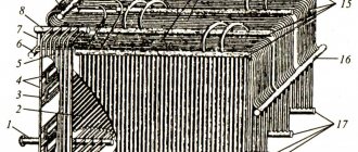
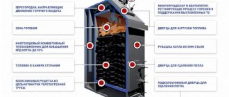
Metal frame with grate device
Fig.5. Metal frame with grate device
(Notations on the diagram: 1 - intermediate screen; 2 - lining of the rear part of the firebox; 3 - pipe D=133 mm; 4 - firebox hatch for working on coal; 5 - firebox hatch for working on wood; 6 - fire-resistant brick; 7 - frame made of m/c; 8 - mounting unit for the boiler and frame; 9 - grate; 10 - hole for supplying air to the boiler; 11 - window for cleaning the boiler furnace; 12 - casing of the convection block; 13 - gas-oil burner.)
The boiler is installed on a metal frame with a grate, which is an all-welded structure. The advantages of this type of design include:
1. Reducing the installation time of the installation, as well as reducing the total cost of the boiler
2. Water coming from inside cools the pipes on which fuel (wood) is burned.
3. On all sides, the structure of the installation is sheathed with metal sheets, in which special windows are made, providing uniform access of air into the firebox and allowing it to be cleaned of ash directly from the inside. Between the pipes there is a free space of 50 mm wide, thanks to which the air is distributed evenly throughout the entire space of the firebox, and ash, slag and other combustion products can freely fall onto the floor of the firebox.
Seporators
As primary separation devices, fender shields and guide visors installed in the upper drum are used, ensuring the supply of the steam-water mixture to the water level. A perforated sheet and a louvered separator are used as secondary separation devices.
The fender shields, guide visors, louvered separators and perforated sheets are made removable to allow complete inspection and repair of the rolling connections of the pipes with the drum and the drum itself. All separation devices are attached to half-clamps welded to the drum using studs and nuts. Disassembly and assembly of louvered separators and perforated sheets is carried out element by element. Dismantling of fender shields begins with the lower shield. Assembly of separation devices is carried out in the reverse order.
When assembling steam separation devices, you should pay attention to creating a tightness in the places where the fender panels are connected to each other and in the places where they are attached to the half-clamps, as well as in the places where the guide visors are connected to the strip with studs: install new paronite gaskets, lubricated with graphite.
If it is necessary to adjust the water chemistry of boilers, the introduction of phosphates should include a line between the economizer and the boiler.
Drainage and air pipes
The boiler design includes drainage pipes, which are necessary to drain water from the installation’s pipe system during its repair, conservation and long-term downtime; moreover, air escapes through them when the system is filled with network water during the boiler startup process. There are three lower points of the vertical collectors, to which the fittings necessary for drainage of water and drainage pipes measuring 28x4 mm are welded. For the manufacture of pipes, steel grade ST 3 was used. At the ends of the pipes, brought out on the right side through the frame casing, there are cylindrical pipe threads. During installation, the ends of the pipes are connected to ball valves DN20.
Purging
On boilers with steam capacity 4; 6.5 and 10 t/h, continuous blowing is provided from the lower collector of the rear screen (in the case when the rear screen has a collector). On boilers with steam capacity 4; 6.5 and 10 t/h in which the rear furnace screen is made of C-shaped Ø51 mm, periodic boiler blowing is combined with continuous blowing, carried out from the front bottom of the lower drum: it is recommended to insert the periodic blowing pipeline in the gap between the shut-off and regulating body on the line continuous blowing.
Boilers with a steam capacity of 16 and 25 t/h have continuous blowing from the second evaporation stage (salty compartment) of the upper drum and periodic blowing from the clean and salty compartments of the lower drum and the lower collector of the rear screen (in the case where the rear screen has a collector).
Flue gases
Flue gas output from boilers with steam capacity 4; 6.5 and 10 t/h are carried out through a window located on the rear wall of the boiler. On boilers with a steam capacity of 16 and 25 t/h, the exit of flue gases is through a window in the left side wall of the boiler at the end (along the gas flow) of the convective beam.
To clean the outer surface of the convective beam pipes from deposits, the boilers are equipped with stationary blowers or a wave generator (GUV).
The blower has a pipe with nozzles that must be rotated when blowing. The outer part of the apparatus is attached to the casing of the left convective wall of the boiler. The blower pipe is rotated manually using a flywheel and chain.
For blowing, saturated or superheated steam from operating boilers is used at a pressure of at least 0.7 MPa.
Comparison of convection and condensing boilers
In searching for a suitable option, users are faced with the need to choose from various types of boilers. Now we need to take a closer look at the convection boiler - what it is and how it works:
- Small amount of condensate formed during operation.
- You can choose from wall-mounted or floor-mounted options.
- They can use a cast iron heat exchanger, which is excluded when using a condensing boiler.
- A convection boiler uses an open combustion chamber, thanks to which it takes air from the room where it is installed, cooling the air.
- Such boilers require simple installation. During operation, problems almost never arise with them.
- They have a relatively simple and straightforward design.
- During operation, the noise level remains insignificant.
- The industry offers many single or dual circuit models. The first of them are designed to ensure heating operation. The latter additionally supply the house or apartment with hot water.
The disadvantage of using such boilers is that the power is limited to 100 kW. They are used for houses with a total area of no more than 300 square meters. meters.
A gas convector can be considered as an element of room design Source cosmo-frost.ru
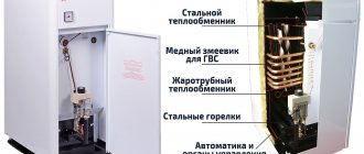
It should be noted that condenser boilers also have their advantages. One of them is the high efficiency of such equipment. Their design has significant differences. The main features are considered to be the following:
- To heat the coolant, not only the combustion chamber is used, but the heat generated by hot steam.
- Before going into the chimney, the smoke is cooled, creating a chemically aggressive condensate that affects the device. In this regard, it cannot be made of cast iron, but stainless steel is used instead.
- The heating efficiency is significantly higher than that of a convection boiler.
- Such boilers cannot provide sufficient traction force, so they use a fan.
- This equipment uses a closed combustion chamber.
- At a power below 30 kW, combustion products can be discharged through the wall. When this value is increased, it is necessary that the pipe be laid through the roof.
- During operation, liquid condensate occurs, which requires drainage to the sewer system. It forms an acidic environment that must be neutralized before draining.
- The formation of condensation does not have a strong impact on the chimney, but it is recommended to make it from acid-resistant materials. When using brick chimneys, inserts from special ceramics are made for such equipment.
This type is more expensive, but a condensing boiler has much greater efficiency. It is important to note that for such a device to operate effectively, it is necessary to use more powerful radiators so that the coolant has time to cool down before it enters the boiler again for warming up. If this condition is not met, then the operating efficiency will not be maximum. You need to know exactly if you choose a condensing or convection boiler: what it is and how it works.
Using a coaxial chimney Source cosmo-frost.ru