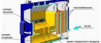
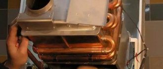
Despite the variety of heating equipment, solid fuel boilers are still in great demand, especially in places where gas supply is difficult, there are difficulties in organizing the storage of liquid fuel, and power outages often occur. Let's consider the principle of operation and piping diagrams of solid fuel boilers.
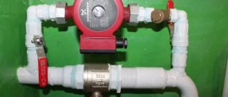
Connection diagram of a solid fuel boiler with a heating system
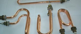
Features of solid fuel boiler operation
This heating system generates heat by burning solid fuel (wood, coal, peat, pellets). It is distinguished by its features, which directly affect its effectiveness and safety:
- Inertia. A solid fuel boiler cannot be stopped immediately. After the oxygen supply is stopped, the system continues to operate until the oxygen inside the firebox runs out, or until the fuel burns out. This can lead to overheating of the coolant and the formation of a large amount of steam. The result is destruction of the boiler body or parts of the heating system.
- Condensate. Appears when the boiler is connected directly, low-temperature coolant passes through the boiler tank. Leads to corrosion of the steel walls of the fuel tank. At the same time, when mixed with ash, it turns into a sticky mass that is difficult to clean off.
To eliminate the problems listed above, it is necessary to properly organize the boiler piping with the obligatory inclusion of a safety group in it. Let's take a closer look at why the piping of a solid fuel heating boiler is needed and the basic installation diagrams.
General installation instructions
Before purchasing a heating unit, you need to determine where it will be installed. The furnace room is designed for this, but often there is not enough free space in it, since it is occupied by an existing gas or other heater. Then the installation of a solid fuel boiler in a private house can be done behind the wall of the furnace room, in an extension. A frame made of metal structures is installed and covered with sandwich panels or profiled sheets with insulation. This option is convenient for those who plan to burn with coal; there will be no dirt inside the house.
All inexpensive solid fuel boilers for low-power homes can be placed directly on the rough floor screed. They are light in weight and do not exert vibration loads on the base, since they are not equipped with a fan or screw conveyor for feeding pellets. For units with a power of over 50 kW, it is recommended to build a concrete foundation, which should rest on the ground and compacted crushed stone bedding. The foundation is made 80-100 mm above the level of the screed, and it should not be connected to it. Foundation devices also require long-burning boilers, which have a mechanism for lifting and lowering heavy loads.
Projects for private houses usually provide for the installation of a chimney shaft in the thickness of the wall with a pipe exiting through the roof. If the shaft is missing or occupied by an existing gas heater, you will need to install a chimney for a solid fuel boiler. To do this, it is better to use metal double-walled chimneys with insulation. They are lightweight, assembled from sections of the required length and are easily attached to the wall of the house. For turns and branches, the same double-walled tees and bends are made. Methods for installing chimneys with and without an exhaust shaft can be seen in the figure.
Chimney installation
The furnace room must have natural exhaust ventilation. When heating boilers are installed in a private house, the exhaust is provided through a shaft in the wall. The shaft is parallel to the chimney, only with a smaller cross-section. If it is not available, a transfer grille is installed in the outer wall; it should be located under the ceiling of the room. The role of the hood is as follows:
- A vacuum is created in the furnace room, as a result of which fresh air from other rooms is sucked in and used for combustion. Boiler systems with a power of 50 kW and above require the organization of separate supply ventilation.
- Removing combustion products that accidentally entered the room.
The approximate layout of the equipment and the installation diagram of a solid fuel heating boiler are shown in the figure.
Solid fuel boiler installation diagram
Often in boiler rooms of country houses there is no sewerage outlet. This is not entirely correct, since sometimes it is necessary to empty the system or the water jacket of the boiler. The safety valve discharge is directed into the same drain.
Installation procedure
To perform the work, the following instructions for installing solid fuel boilers are proposed:
- Release the product from its original packaging.
- If there is not enough space in the furnace room, then it is better to assemble the product outside. Install all doors and ash pan drawer, as well as other elements supplied separately. There is no need to install a fan and automation devices; this is done after installing the boiler.
- Move the unit indoors and install it on the foundation or floor so that the gas outlet pipe is on the same axis with the chimney pipe. At home, installing a solid fuel boiler yourself must be done with an assistant; the weight of the equipment is rarely less than 50 kg.
- Secure the boiler to the foundation or screed so that there are no distortions.
- Connect the chimney, install a fan with a control unit and a safety group.
- Connect the boiler to the heating system according to the selected scheme.
Piping of a solid fuel heating boiler. Purpose. Elements
The most important purpose of the piping is to ensure efficient, safe, economical operation of the boiler. This means:
- protect equipment from overheating, sudden pressure changes, maintain the most acceptable temperature;
- control the amount of coolant in the system, remove excess liquid, excess steam;
- remove air from the system;
- distribution function - to divide the coolant between all heat consumers in the system.
The piping elements of a solid fuel boiler and their correct installation in one way or another work to ensure the safety of heating equipment. The main ones include:
- safety group (pressure gauge, air vent, safety valve);
- expansion tank;
- heat accumulator;
- three-way mixing valve.
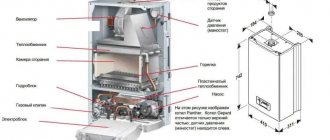
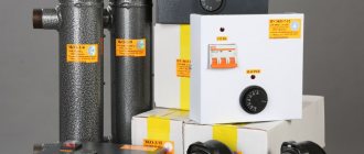
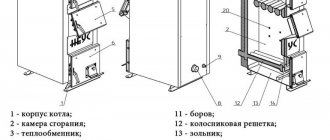
Heating boiler
Piping rules that must be followed when independently connecting a solid fuel heating system:
- to avoid the appearance of condensation, the temperature difference between the supply and return should not exceed 20 ⁰C;
- protective devices should be installed that will regulate the coolant pressure throughout the entire circuit;
- It is also recommended to include automatic devices in the piping that are responsible for regulating power and fluid temperature in the system.
These rules work best in systems with forced coolant movement. Let's briefly look at the wiring diagrams for solid fuel boilers. But before that, a few words about the safety group in the heating system.
What else is needed in the system
The boiler piping will be incomplete if it does not have a tap to drain and fill the system. And it is better if they are separate. The specific installation location depends on the structure of the system, but there are certain rules:
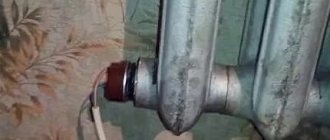
- The drain tap is installed at the lowest point. This is very important if the heating system needs to be preserved for the winter - it is necessary that as little coolant remains in it as possible. If the system will operate constantly in winter, a tap (with or without a pipe) is usually attached to one of the radiators. This will be the place where the system drains. Such a valve for draining the system can be installed in any convenient place (on the return pipeline)
- If the heating system will use water, an inlet from the water supply is usually connected. In the case of a wall-mounted gas boiler, there is a special pipe with a stationary tap for this. Cold water is connected to this input; if refilling is necessary, the tap is opened for a short time. If a boiler without a special pipe is used, a tap is also installed in the supply pipeline (preferably higher). Alternatively, on a section of pipe that goes to the expansion tank.
One of the options for installing a tap for filling the heating system
In some systems, the drain and fill of the system are made from one tap. This is possible if there is a pump that pumps the coolant and there is a pressure gauge by which you can control the pressure created. If there is a separate tap for filling the system at a high point, it can be filled by gravity.
Security group
Includes elements:
- pressure gauge (shows the pressure level in the system) - safety valve (automatically relieves pressure if it exceeds the permissible value of 2 Bar, usually triggers at 3 Bar), - automatic air vent (removes air from the coolant).
Heating scheme
It is installed on the supply pipe of the boiler itself, immediately at the outlet. It is important to remember that no locking mechanisms should be installed between the safety group and the boiler. These devices must be installed in any heating system piping circuit.
Thermal mixing unit from a trusted manufacturer with express delivery throughout Russia
If you set out to ensure the most comfortable microclimate in your home at any time of the year, visit the online catalog of the Kpdsklad.ru store. From us you can buy all the necessary equipment for arranging and automating an individual heating system. Including thermo-mixing unit. All products are supplied directly from the official manufacturer. They undergo thorough testing before being put up for sale and have an official guarantee.
Our store specialists will help you select and buy a mixing unit for a boiler of any model. You can pick up your purchase at one of our pickup points in Moscow, Borisoglebsk, Perm and Yekaterinburg. We also offer express delivery to your place of residence using trusted postal services.
Order high-quality components for the boiler at Kpdsklad.ru! Experience the maximum comfort, benefits and benefits of an individual heating system!
Open type with natural circulation
The simplest wiring with a minimum number of devices, complete independence from electricity. The movement of fluid through the system occurs naturally due to the general arrangement of the pipes at a slight slope. The boiler is installed half a meter below the level of the radiators. Minimum number of locking mechanisms, control devices, etc.
This type of piping is effective for a small house with a small number of heat consumers. An open type expansion tank is installed as high as possible, in the attic, for example.
In this case, the coolant temperature cannot be adjusted. And air often enters through an open expansion tank, which has a detrimental effect on the inner surface of the pipes.
Closed type with natural circulation
It is also a fairly simple piping scheme with a small number of heat consumers. The scheme is very similar to the open type. It is distinguished by the inclusion of a closed expansion tank with a membrane, which is installed on the return pipe. In addition, do not forget about the security group. Some models are already equipped with it in production.
The expansion tank is designed for a volume of more than 10% of the total coolant volume.
There are several important points when lining a heating boiler with polypropylene. The pipe from the heat generator to the safety group is made of metal, then it is laid from polypropylene. Also, the section of the return pipe with an installed three-way valve and sensor is made of metal. Polypropylene has low thermal conductivity. If you install a three-way valve on it, it will respond with a delay to an increase in temperature, and the sensor will provide information incorrectly.
In general, the polypropylene piping system for a heating boiler is beneficial and quite practical.
Installation location
For proper installation of hydraulic arrows, follow 5 general rules:
- For proper operation of the distributor, it does not matter in what position the hydraulic arrow is installed. The only important thing is the direction of the end pipelines, on which the operation of the automatic air vent and the sludge removal system depend.
- The distributor is installed after the boiler valve. The installation location is determined by the heating circuit; it is located as close as possible to the unit.
- If a collector circuit is used, the distributor is placed in front of the boiler unit.
- If it is necessary to connect an additional electric pump, the distributor is placed between it and the outlet pipe for the heating circuit.
- In order to properly connect the solid fuel unit, the hydraulic arrow is connected to the coolant outlet and inlet, then you can adjust the individual temperature for each circuit.
Closed type with forced circulation
A simple circuit with a circulation pump that moves coolant throughout the system. The slope as such is no longer required to be observed. The pump, as well as a temperature sensor (controls the operation of the pump) are installed on the return line (between the expansion tank and the boiler) and connected to the electrical network.
Closed heating circuit with forced circulation
This harness is characterized by greater productivity due to the use of a temperature control device. Can be used where the power supply is stable. Otherwise, if there is a power outage, the heating system will stop.
Gravity circuit
Let's consider a circuit with natural circulation - gravitational. When drawing up a plan, we avoid bends and try to minimize the number of bends so as not to create unnecessary resistance. Based on the size of the pipes of the boiler used, we select the diameter of the pipes for the circuit. The standard option is no more than 1.5 inches.
The coolant circulates within the gravity circuit without the help of a pump due to the temperature difference created. If the circulation of hot water stops due to a power outage or for another reason, the solid fuel boiler will boil. To avoid this dangerous situation, an additional gravity circuit is used to prevent an accident if the pump stops.
Sometimes the temperature of a solid fuel boiler increases and can exceed the limit of 100 degrees. For this reason, we tie the circuit with metal pipes. We add a pump to the intended circuit. To do this, we are planning a workaround, where we install a safety leaf check valve on a dedicated section of the gravity circuit. We select a valve with minimal resistance. An adapter with standard resistance may interfere with coolant circulation.
In normal mode, the circulation pump creates pressure on the valve, keeping it closed. In this case, water circulates freely along the usual path. When the pump stops, the boiler continues to heat the water, but the built-in valve will work and will not allow water to flow through the main circle.
Manifold piping with forced circulation
Circulation pump + collectors. This is a characteristic difference between the manifold piping system.
The pump moves liquid through the pipes. Collectors (so-called combs) are connected to the heating system. They are pipes with a large cross-section. They have one common input and several outputs for connecting the required number of heating elements (for example, radiators, underfloor heating system, heated towel rail). Connect to the supply and return pipes of the system.
Heating wiring diagrams
The specificity of such a connection is characterized by a separate supply of coolant to each element of the system with the same temperature and pressure. It features more efficient regulation of the heating system.
It should be taken into account that such piping will take a lot of time, effort, and material costs (high pipe consumption, financial expenses).
Why are emergency and control systems needed?
The heating system can be protected by including emergency and control units in the circuit.
Their purpose:
- Protection against high pressure.
- Thermoregulation.
- Protecting equipment from excess heat.
- Prevents condensation.
How to connect
In order for the units to perform their purpose efficiently, they must be installed correctly.
The emergency unit includes:
- Safety valve. Used to relieve excess pressure. Installed at the feed outlet from the boiler.
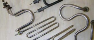
- Heat exchanger. Used to prevent boiler overheating. It is installed either in the boiler structure by the manufacturer or on the hot water supply pipe.
- Bypass. Serves to prevent overheating and boiling of the coolant. Must be installed in units with pumps and auxiliary equipment.
The operation of the system is regulated by a thermostat (installed on the return line) and a pressure regulator. They serve to maintain a constant temperature in the system and protect against pressure build-up.
Harness with hydraulic arrow
The piping system uses a vertical pipe with a large cross-section - a hydraulic arrow. This element is connected to the boiler by supply and return pipes. It is installed in the same place as the collectors: after the expansion tank, in front of the heating elements (radiators, heated towel rail, etc.).
Diagram of a heating system with a hydraulic arrow
It differs from collectors in that it can be connected to the hydraulic arrow at different heights. This directly affects the temperature of the coolant, and with it the temperature of each heating element in the house. Thus, using a harness with a hydraulic arrow, you can create an optimal thermal regime for each device separately.
Insulation of fittings
Let's consider the issue of the need to insulate the fittings. Long pipe lengths, many fittings and high operating temperatures in the system lead to heat loss. At finished facilities, heating equipment that is not properly insulated overheats the surrounding space. In the room where the boiler and heat accumulator are installed, the temperature can reach plus 27 degrees in severe frost. Fuel is wasted and system efficiency decreases. After insulating the pipes, it is possible to gain a few degrees and reduce fuel consumption.
When insulating the fittings, you must remember that when working from the side of the boilers, the pipes become very hot, since they can transport water hotter than 100 degrees. Polyethylene foam insulation is not suitable in this case. It can only be installed in another part of the circuit on the side of the radiators of the heating system. In a boiler room, it is better to put rubber insulation that is more resistant to heat on hot pipes. It is also worth additionally insulating fittings and other fittings.
For safety reasons, it is not recommended to insulate pumps. This equipment is limited to exceed ambient temperature limits. If you insulate the pumps from the boiler side, you can insulate them too much, and this is unacceptable.
Connecting a solid fuel boiler with a heat accumulator
For equipment operating on solid fuel, it is recommended to install a heat accumulator. It is a buffer tank for accumulating and then storing the heat generated by the boiler.
A very profitable device, because it allows you to increase the efficiency of solid fuel equipment and at the same time save heating material.
The wiring diagram for a solid fuel boiler with a buffer tank is as follows. The inlet and outlet pipes from the heat generator are connected to the heat accumulator, and from it to the heating elements. Now two contours are formed at once:
- between the heat buffer and the boiler;
- between the buffer and the heating devices of the house.
As the coolant passes through the heating system, it fills the buffer tank. In this case, cooled liquid from the heating elements passes below, and hot liquid from the boiler passes above. The buffer accumulates heat when the firebox is operating at full power. After the fuel burns out, the accumulated heat from the tank is released through the heating system for a certain period of time. After the storage buffer, a pump and a three-way valve are installed to adjust the temperature of the heating fluid.
The wiring diagram of a solid fuel boiler with a battery tank saves fuel, allowing you to add coal and firewood much less frequently. It must be taken into account that with such piping, the boiler power should be sufficient for heating and warming up the buffer tank.
Recommendations for choosing and connecting radiators
An ordinary homeowner, going to a heating equipment store and seeing a wide selection of different radiators there, can conclude that choosing batteries for his home is not so easy. But this is the first impression; in fact, there are not so many varieties of them:
- aluminum;
- bimetallic;
- steel panel and tubular;
- cast iron
Sectional batteries made of aluminum alloy have the best heat transfer rates; bimetallic heaters are not far behind them. The difference between the two is that the former are made entirely of alloy, while the latter have a tubular steel frame inside. This was done for the purpose of using the devices in centralized heat supply systems of high-rise buildings, where the pressure can be quite high. Therefore, installing bimetallic radiators in a private cottage makes no sense at all.
It should be noted that heating installation in a private home will be cheaper if you purchase steel panel radiators. Yes, their heat transfer rates are lower than those of aluminum ones, but in practice you are unlikely to feel the difference. As for reliability and durability, the devices will successfully serve you for at least 20 years, or even more. In turn, tubular batteries are much more expensive, in this respect they are closer to designer ones.
Steel and aluminum heating devices have one useful quality in common: they lend themselves well to automatic control using thermostatic valves. The same cannot be said about massive cast iron batteries, on which it is pointless to install such valves. This is due to the ability of cast iron to heat up for a long time and then retain heat for some time. Also because of this, the rate of heating of the premises is reduced.
If we touch on the issue of appearance aesthetics, then the cast-iron retro radiators currently offered are much more beautiful than any other batteries. But they also cost incredible amounts of money, and inexpensive Soviet-style accordions MS-140 are only suitable for a one-story country house. From the above, the conclusion suggests itself:
Wiring a solid fuel and gas boiler (electric boiler)
This harness is relevant and in demand among residents of country houses. It allows you to organize year-round comfort in the house, including several heating sources in the overall system. As a rule, steam from a gas heating boiler with a solid fuel device is installed, as well as solid fuel equipment with an electric boiler.
Solid fuel boiler+electric
The wiring diagram for gas and electric devices with wood is the same , it is quite simple, because it uses a heat accumulator at the same time as a hydraulic arrow. This allows you to efficiently supply heat to a large number of heating points at once (radiators, heated floors, boiler, heated towel rail, etc.). In this case, the heat from the gas heating boiler (electric) and wood-burning boiler charges the buffer tank, and then it supplies thermal energy to the heating end points.
There is also another option for connecting a gas heating boiler (electric boiler) and a solid fuel boiler together, without using a buffer tank, because this is quite expensive. Here the main source of heating is a wood-burning boiler, with a gas boiler as an auxiliary one.
Operating principle. After solid fuel burns out, the air temperature decreases. This detects the sensor installed in the room and immediately starts the gas boiler. When the main boiler cools down, it switches off automatically. The gas one operates until the wood-burning unit begins to process the next portion of fuel. Now, in reverse order, the room temperature sensor turns off the gas heating device.
The scheme with such a harness is simple, you can install it yourself.
Basic requirements for the boiler room
Domestic solid fuel heat generators are installed in separate dry rooms, outbuildings or separate buildings. The dimensions of the boiler room are determined by the dimensions of the unit, as well as the features of its maintenance, however, the smallest allowable area is 7 square meters. In this case, it is necessary to provide a place protected from atmospheric influences for storing the fuel supply - it must be dry before loading.
3D diagram of a heating system with a solid fuel boiler
If the walls of the boiler room are made of flammable materials, they must be covered with a 2.5-3 cm layer of plaster or thermal insulation in the form of an 8 mm layer of asbestos and sheet iron. If there is no fire protection for the ceiling, the distance from it to the boiler body must be at least 120 cm.
The normal operation of a solid fuel boiler is ensured by a stable air flow. Therefore, it is necessary to provide supply and exhaust ventilation in the boiler room. The first channel, measuring 30x30 cm, should go to the bottom of the wall opposite the chimney, and the exhaust hole, whose dimensions should be 40x40 cm, should be located no more than 40 cm from the ceiling. The boiler room ventilation must ensure normal draft. If there is a shortage of it, the boiler’s performance drops, and if there is an excess, it becomes difficult to regulate the fuel combustion process.
Supply and exhaust ventilation and smoke removal in the boiler room
The solid fuel boiler must be installed on a strictly horizontal fireproof (concrete or brick) platform about 7 cm thick. On a wooden floor, such equipment can only be installed with an intermediate brick layer covered with a 3-4 mm metal sheet or at least 5 cm cement screed . The base of a solid fuel boiler should be 10-20 cm wider than the external dimensions of the body, but the sides of the firebox should be additionally equipped with a safety zone at least 40 cm wide.
Piping with connection of an indirect water heater
The wiring diagram for a solid fuel boiler with a boiler is quite common due to its cost-effectiveness and efficient operation. This is especially relevant during the heating season, when you can save a significant amount on electricity.
This piping is designed in such a way that the heated liquid is supplied simultaneously to the boiler and radiators. In this case, the boiler circuit is connected to the heat exchanger of the water heater, which heats the water indirectly.
Often, an additional method of heating liquid (gas, heating element) is installed in the boiler in case the heating is turned off (warm season).
The considered piping can be used with all heating devices with both natural and forced circulation of liquid.
Buy or make it yourself
A ready-made set of European-assembled hydraulic guns with auxiliary equipment in the retail chain costs from 200 to 300 US dollars.
The user who purchases such a design will receive all the advantages of its operation in the heat supply system: fuel economy, reliable thermal and hydraulic conditions in the network and durability of the main boiler equipment.
Simple diagram of a hydraulic separator
Factory assembly solves not only distribution issues, but also protection of the system from water hammer, corrosion and sludge deposits in internal heating surfaces. All structural components are carefully calculated, manufactured using modern technology and adjusted in the factory.
Those home craftsmen who want to save money on distributors have plumbing experience and all the necessary equipment can be advised to make the hydraulic switch themselves, fortunately today there are quite detailed manufacturing methods and schemes on the Internet. The device belongs to complex hydraulic products and when performing them, the following must be taken into account:
- The drives must have a symmetrical, well-cut thread.
- The wall thickness of the pipes is chosen to be the same.
- The quality of welds must be high.
How to choose a hydraulic gun
The hydraulic arrow works effectively only if it is selected correctly. The basic characteristics when choosing a distributor are the thermal power of the boiler and the total hourly water consumption for all boilers. It should not exceed the hourly water flow through the boiler circuit.
Next, pay attention to the design features of the hydraulic arrow:
- cross-sectional shape - square or round
- number of pipes: 4, 6 or 8 inputs/outputs;
- water supply/discharge option;
- method of installation of pipes - on a common axis or with alternation.
Experts advise purchasing ready-made structures with pressure gauges, an air vent and a sump for cleaning the water circuit from sludge for wall-mounted boilers and hydraulic taps.