Automation of production, technological processes, operation of household and other appliances is often associated with monitoring temperature changes; high-precision sensors with low inertia - thermocouples (TC) are used there. Differences from other temperature meters, for example, from thermistors: the principle is based on the generation of current when the soldered electrodes are heated, the temperature range is much wider. There are also disadvantages: the need for amplifiers, converters, sometimes certain conditions are needed to reduce errors. With a multimeter, the TP is used to study the heating of electronics and other objects. Let's consider what a thermocouple is, advantages and disadvantages, features, types. We will describe where thermoelectric converters are more appropriate and how to assemble them yourself.
Thermocouple concept
Thermocouples (thermoelectric converters, TC) are sensors for measuring t°, based on the principle of transforming heat into electrical processes.
The thermoelectric converter itself does not process the readings, but transmits them to a separate unit for this purpose, to the application chip (serviced or special measuring equipment).
The thermal converter sensor has sufficient accuracy and low inertia. The operating temperature range is wider than that of thermistor sensors, as well as better resistance to mechanical and other loads (these are the main advantages).
Measurement speed
The performance is determined by the ability of the primary converter to quickly respond to temperature surges and the subsequent flow of input signals from the measuring device.
Factors that increase performance:
- Correct installation and calculation of the length of the primary converter;
- When using a converter with a protective sleeve, it is necessary to reduce the mass of the assembly by selecting a smaller diameter of the sleeves;
- Minimizing the air gap between the primary converter and the protective sleeve;
- Using a spring-loaded primary converter and filling the voids in the sleeve with a heat-conducting filler;
- A fast moving or denser medium (liquid).
Where are thermocouples used?
TP is more often used than other sensors for equipment associated with high positive temperatures: fuel boilers and stoves, other equipment with burners, boilers, soldering irons, pyrometers, furnaces, metallurgy.
The term "thermoelectric converter" reflects the nature of the sensor - a differential meter that makes measurements by converting heat into electricity.
Thermocouples are simple and effective sensors for high-precision thermoelectric thermometers operating at elevated temperatures.
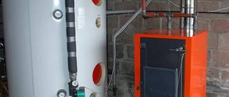
A striking example of application: in automatic components for fuel boilers and heating. The activation of the equipment is initiated by an electrical signal from the sensor node with the TP.
Thermocouples, along with NTC and PTC thermistors, are the most popular temperature meters for equipment; the latter have their advantages (they are considered more accurate in their ranges), but do not cover such a wide temperature range as TCs.
Design features
If we take a more scrupulous approach to the process of measuring temperature, then this procedure is carried out using a thermoelectric thermometer. The main sensitive element of this device is a thermocouple.
The measurement process itself occurs due to the creation of an electromotive force in the thermocouple. There are some features of the thermocouple device:
- The electrodes are connected in thermocouples to measure high temperatures at one point using electric arc welding. When measuring small indicators, such contact is made using soldering. Special connections in tungsten-rhenium and tungsten-molybdenum devices are made using tight twists without additional processing.
- The elements are connected only in the working area, and along the remaining length they are isolated from each other.
- The insulation method is carried out depending on the upper temperature value. With a value range from 100 to 120 °C, any type of insulation, including air, is used. At temperatures up to 1300 °C, porcelain tubes or beads are used. If the value reaches up to 2000 °C, then insulating material made of aluminum oxide, magnesium, beryllium and zirconium is used.
- Depending on the environment in which the sensor is used, in which the temperature is measured, an external protective cover is used. It is made in the form of a tube made of metal or ceramics. Such protection provides waterproofing and surface protection of the thermocouple from mechanical influences. The material of the outer cover must withstand high temperatures and have excellent thermal conductivity.
You might be interested in Kilowatt - a derived unit of measurement of power
The design of the sensor largely depends on the conditions of its application. When creating a thermocouple, the range of measured temperatures, the state of the external environment, thermal inertia, etc. are taken into account.
What is a thermocouple and its device
TP is regulated by GOST 6616, R 8.585 and IEC 62460, 60584. Clause 2.2 of the latter defines a sensor: a pair of different alloy conductors with a connection (solder) at one end to initiate a thermoelectric effect for measuring t° with this segment. TP measures the connection point (head) of its electrodes, the so-called “hot junction”.
You need to understand that the thermocouple device may consist of unsightly pieces of thin wires soldered at one end, but despite this, the sensor is extremely effective. Often contains precious metals.
Device:
- two conductors, soldered at one end, less often twisted. This is the hot junction, the sensitive segment that takes measurements;
- the other ends are a place where there is no heating, connections to extension wires, a cold junction. They are connected to the indicator receiver.
A closed circuit is created; if a galvanometer, microvoltmeter, or multimeter is connected to its break, they will show the thermoEMF of several milli- or microvolts that has arisen there. The value depends on the degree of heating at the wire connection and on the temperature indicator in the segment where there is none.
That is, the magnitude of the EMF depends on the difference in t° between the cold and hot junctions and on the thermoelectric properties of the alloys of the conductors themselves.
If the hot point of the connection is heated, then a potential difference will appear between their unconnected (cold) ends.
Next, a separate converter or on the control unit of the device being serviced calculates the temperature, since the strength of the EMF and it are interdependent, then converts the received data into numbers and/or into commands for control.
Design and principle of operation
It is known that in a closed circuit, which consists of two conductors of different metals (for example, chromel and copel), a thermoelectromotive force (EMF) arises, provided that their hot and cold junctions have different temperatures (Seebeck effect). The value of the EMF depends on the materials of the conductors, the temperatures of their cold and hot junctions.
Typically, the voltage of a household thermocouple is in the range of 20-60 millivolts (mV), which is enough to open the gas valve, but, of course, not enough to operate complex automation and other modules that already require an electrical connection.
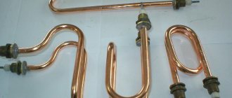
This is what a standard thermocouple looks like in the photo.
The module is not limited to a pair of junctions, but the thermocouple device is quite simple and understandable:
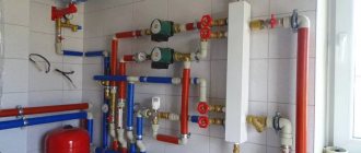
- The sleeve, inside of which there are thermoelectrodes with the “hot” junction of the conductors, is what is attached to the burner module of the boiler, next to the pilot burner (igniter).
- An extension cord, protected by a copper tube from external influence of electromagnetic fields, is used to connect the working part (hot junction) with the electromagnetic gas valve.
- A dielectric washer with a “cold” junction, it is this that is inserted into the socket of the gas solenoid valve.
Most often, thermocouples of domestic gas boilers use junctions made of chromel and alumel (TCA), chromel and copel (TCC), and iron and constantan (TLC). All alloys used, their markings and characteristics are listed in the table below.
| Thermocouple type (European classification) | Junction conductor materials | Russian markings | Temperature range, °C |
| K | chromel-alumel | THA | -200 – 1 300 |
| L | chromel-copel | THC | -200 – 850 |
| J | iron-constantan | TZHK | -100 – 1 200 |
| N | nikhrosil-nisil | TNN | -200 – 1 300 |
| T | copper-constantan | TMKn | -200 – 400 |
| E | chromel-constantan | THKn | 0 – 600 |
| S | platinum-rhodium-platinum | TPP10 | 0 – 1 700 |
How does a thermoelectric thermometer work as part of a gas boiler?
The operating principle of a thermocouple in a gas boiler is the same everywhere:
- First, a person mechanically opens the gas supply valve by holding the solenoid valve button for 15-30 seconds.
- Then the piezo ignition button is pressed once, a spark appears and the pilot burner lights up.
- The magnetic valve button is held down for another 30-60 seconds until the working junction of the thermocouple, located next to the igniter, heats up and produces the required voltage.
- After 30-60 seconds, the solenoid valve button is released, but combustion continues as the heated thermocouple produces enough voltage to hold the gas valve open. The boiler operates normally, without human intervention.
- Once combustion stops, the flame no longer heats the thermocouple, causing the voltage to be insufficient to hold the gas solenoid valve open and it closes, stopping the flow of gas.
What is KHS
For particularly accurate measurements, the temperature in the cold segment must remain constant, but this is difficult to achieve under normal conditions, so special compensation circuits are used. The voltage recorded at the specified section of the TP depends on the difference in t° on it and on the hot segment. Therefore, you need to know the heating level of the first to calculate that of the second. Such calculations are called cold junction compensation - CJC and it is often used for emergency shutdowns or to control other pulse generation units.
They always strive to measure (calculate) CHS closer to the point of intended measurements with a thermocouple, since extended wires are sensitive to electrical interference (the signal deteriorates). This circumstance is significant for manufacturers when designing temperature sensors.
Principle of operation
The thermocouple, whose operating principle is based on the effect discovered by T. Seebeck in 1822, is a purely differential sensor.
This principle is as follows: in a closed circuit of two conductors of different types, if there is a temperature gradient between the junctions, an electric current appears. Thermocouples create an electrical signal that is proportional to the temperature difference between two different points. Thus, the junction used to measure the required temperature is called the “hot” junction, and the other junction is called the “cold” junction.
Typically, the temperature being measured is higher than the temperature at which the measuring device is located. Difficulties in using pairs relate to the use of cold junction voltage. Basically, what is required is to measure the temperature at a specific point, rather than the difference in temperature between two points, which is what a thermocouple does.
Operating principle
In short, the TC consists of wires made of 2 different alloys with their own electrical characteristics under thermal influences: a certain potential difference and a weak current are created, which is recorded by the receiver of such readings.
But if you delve deeper into the study of a thermocouple, then you need to talk about significant special nuances of how it works.
The operating principle of a thermocouple uses thermoelectric response, first described by the scientist T. Seebeck. The connected conductors have a contact potential difference. Structurally, the sensor consists of 2 cores made of different alloys.
The ends form a head - a contact, the so-called hot junction (red in the diagram below), created by twisting, and more often by welding (seam, butt). The free ends go to the processing data, control units of the equipment being serviced, they are closed by compensation wires to the contacts of such devices, and at the connection points with the TP there is a cold junction (blue in the figure below).
Electrodes made of different metals, conventionally A and B, are also shown in different shades in the drawing above. They are protected by a sealed capsule (may contain an inert gas or liquid), ceramic cylinders (shown in the image below).
Explanation from Wikipedia:
The action is based on an effect with thermoelectric properties (named after the scientist T. Seebeck). If the circuit is closed, for example, with a millivoltmeter, thermo-EMF (electromotive force) appears at the junction points. If we used electrodes from the same alloys, then they would heat up equally (equivalently), the EMF would be mutually compensated, and no current would arise.
A thermocouple, how it works, what it is in simple terms: different conductors heat up differently, their junctions have non-identical temperatures, so a potential difference arises between them, initiating a thermo-EMF, which maintains a weak current in such a circuit. The value is proportional to the difference in t° of the junctions. It must be emphasized that it is this that needs to be taken into account, and not other indicators.
Another simple explanation of how a thermocouple works: if you connect 2 different metal conductors, creating a closed electrical circuit, and heat the point of this connection, an electromotive force (thermoEMF) and a small electric current will appear. The TP transmits this data to the microcircuit of the serviced or measuring device, which processes it, calculating t°.
Related topics:
Thermocouple (thermoelectric temperature transducer) is a thermoelement used in
measuring and converting devices, as well as in automation systems.
The international standard for thermocouples IEC60584 (clause 2.2) gives the following definition of a thermocouple:
Thermocouple - a pair of conductors made of different materials connected at one end and forming
part of a device that uses the thermoelectric effect to measure temperature.
To measure the temperature difference between zones, one of which does not contain a secondary converter
(thermo-EMF meter), it is convenient to use a differential thermocouple: two identical thermocouples,
connected towards each other. Each of them measures the temperature difference between its worker
solder with a conventional junction formed by the ends of thermocouples connected to the terminals of the secondary
converter, but the secondary converter measures the difference. their signals are thus two
thermocouples together measure the temperature difference between their working junctions.
The operating principle is based on the Seebeck effect or, in other words, the thermoelectric effect.
When the ends of the conductor are at different temperatures, a potential difference arises between them, proportional to the temperature difference. The proportionality coefficient is called the thermopower coefficient. Different metals have different thermopower coefficients and, accordingly, the potential difference arising between the ends of different conductors will be different. By placing a junction made of metals with excellent thermoelectric coefficients in a medium with a temperature T1, we will obtain a voltage between opposite contacts located at a different temperature T2, which will be proportional to the difference in temperatures T1 and T2.
Features, nuances of accuracy
The voltage at the cold tips is proportionally dependent on t° in the area of the hot junction. In a certain temperature range, a linear thermoelectric property is observed, showing the dependence of the voltage on the level of difference t° between the points of the warm and cold element of the TC. Linearity is conditional - we can talk about it only when t° at the latter is constant. This nuance must be taken into account if calibration is being done: when changing the heating at the cold ends, there is a possibility of a significant error
When high measurement accuracy is required, the cold ends are placed in special capsules, where the stability of one selected temperature level is maintained by special electronic devices that process the resistance thermometer readings. With this approach, accuracy up to ±0.01 is achieved. But this is required only for a few technological processes. In most cases, for example, when operating thermocouples in refrigerators, water heaters and other household appliances, the requirements are less stringent and allow deviations an order of magnitude lower.
Recommendations for use
The accuracy and integrity of a thermocouple sensor-based measurement system can be increased if certain conditions are met. Avoid vibrations and mechanical tension on thermocouple conductors. When using a miniature thermocouple made of thin wire. It should only be used in a controlled location, and extension leads should be used beyond that location. It is recommended to use large diameter wire that does not change the temperature of the measured object. Use the temperature sensor only within the operating temperature range.
Table - Calibration and testing of thermocouples.
Avoid sudden temperature changes along the length of the temperature sensor. When working with long temperature sensors and extension conductors, it is necessary to connect the voltmeter screen to the wire screen. For auxiliary control and temperature diagnostics, special temperature sensors with 4 thermoelectrodes are used, which allow auxiliary measurements of temperature, resistance, voltage, interference to check the reliability and integrity of thermocouples.
Carry out electronic recording of events and constantly monitor the resistance value of thermoelectrodes. Use extension conductors within the operating range and at the smallest temperature differences. Use a quality protective cover to protect the thermocouple leads from harmful conditions.
Differences between thermocouples and thermistors (NTC PTC)
Differences between thermoelectric converters and thermistors (resistance sensors):
- principle of operation. A small current appears on the thermocouple, changing with different heating of its head, and the thermistor (semiconductor) reacts to such processes by changing its resistance;
- constructive. Thermocouple design: two soldered conductors (the current flows from them) made of different alloys in a protective casing and with compensation wires, the thermistor is a solid piece of semiconductor with conductors (the current flows to it), the resistance of which is sensitive to temperature.
The thermocouple has the following advantages:
- operating range t° is much higher: the typical one reaches +600...+800° C, thermistors have a standard maximum positive limit of about +200...+600° C. There are thermocouples made of special alloys that operate at +2500° C, which cannot be called anything for them - outstanding, these are, in general, ordinary parameters. But thermal sensors also have special families of high-temperature models. But these are more special devices, and yet their range is smaller;
- thermistors are more accurate, but with some caveats. At high temperatures, errors, as well as degradation, their calibration may be higher than that of TP. That is, at particularly high temperatures, thermocouples can be more accurate. This minus for them is also leveled out if there is a converter that calculates errors;
- often a normalizing amplifier is required, which is needed for a thermocouple, to increase sensitivity so that its signal is stronger for better operation of the receiver processing the information so that it “sees” it;
- The thermistor is cheap due to the fact that it does not require the specified additional components. For TP such devices are often required, so in the end the cost of their use is higher;
- resistance to mechanical influences and vibrations of thermocouples is better, they have reliable protective covers;
- the reaction speed of TCs is higher than that of thermistors;
- When working at elevated temperatures, thermistors are more susceptible to wear and miscalibration. But this minus is relative - such a sensor is often simply thrown away and a new one is bought, since the product is cheap;
- Thermistors degrade faster over time. Manufacturers usually provide a warranty of only 1000 hours for such detectors. Thermocouples are more durable.
So, measuring temperature with a thermistor and a thermocouple differs fundamentally, although in both cases it is based on electrical parameters: the second creates and changes the EMF, the first - its resistance.
There is a rule: if the temperature is above +300° C, then a thermocouple should be used. Thermistors are more common on simpler and cheaper devices. Expensive and complex equipment uses thermocouples, which are also more common when working with high temperatures. Thermistors under such conditions may have the same errors as TCs, but in typical ranges (−50...+300° C) they have superior accuracy.
If we talk about special narrowly focused areas - laboratories, special research, industry - then TP is more often used there.
Let's summarize:
- advantages of a thermocouple: the operating temperature range is much wider, the response is faster, the service life is much longer than that of thermistors, TCs are less susceptible to miscalibration, degradation, and mechanical damage. In the temperature range from +300° C, thermocouples are often irreplaceable;
- disadvantages: the peculiarities of using TCs increase costs (partially offset by survivability), and it is also generally accepted that the accuracy of thermocouples is slightly worse than that of thermistors.
Let us separately highlight an absolute plus: only thermocouples are used as temperature meters of the objects under study (radio components, etc.) together with a multimeter. It must also be said that unsuitable t° ranges always increase errors and the likelihood of failure, but the TP is resistant to such conditions.
Features of the use of the most common thermocouples
Technical characteristics depend directly on the materials from which they are made.
Type J (Iron Constantan Thermocouple)
- It is not recommended to use below 0°C, because Moisture condensation on the iron terminal leads to the formation of rust.
- The most suitable type for rarefied atmospheres.
- The maximum temperature of use is 500°C, because Above this temperature, rapid oxidation of the leads occurs. Both terminals are quickly destroyed in a sulfur atmosphere.
- The readings increase after thermal aging.
- Low cost is also an advantage.
Type E (chromel-constantan thermocouple)
- The advantage is high sensitivity.
- Thermoelectric homogeneity of electrode materials.
- Suitable for use at low temperatures.
Type T (copper-constantan thermocouple)
- Can be used below 0°C.
- Can be used in atmospheres with slight excess or deficiency of oxygen.
- Use at temperatures above 400°C is not recommended.
- Not sensitive to high humidity.
- Both leads can be annealed to remove materials causing thermoelectric inhomogeneity.
Type T thermocouples.
Type K (chromel-alumel thermocouple)
- Widely used in various areas from -100°C to +1000°C (recommended limit depending on the diameter of the thermoelectrode).
- In the range from 200 to 500°C, a hysteresis effect occurs, i.e., readings during heating and cooling may differ. Sometimes the difference reaches 5°C.
- Used in a neutral atmosphere or an atmosphere with excess oxygen.
- After thermal aging, the readings decrease.
- It is not recommended to use in a rarefied atmosphere, because... chromium can be released from the Ni-Cr terminal (so-called migration), and the thermocouple changes the thermoelectric force and shows a low temperature.
- A sulfur atmosphere is harmful to a thermocouple because affects both electrodes.
Type K thermocouple.
Type N (nicrosil-nisil thermocouple)
- This is a relatively new type of thermocouple, developed from the K-type thermocouple. The K-type thermocouple can be easily contaminated by impurities at high temperatures. By fusing both electrodes with silicon, the thermocouple can be precontaminated and thus reduce the risk of further contamination during operation.
- Recommended operating temperature up to 1200°C (depending on wire diameter).
- Short-term operation is possible at 1250°C.
- High stability at temperatures from 200 to 500°C (significantly less hysteresis than for a type K thermocouple).
- Considered to be the most accurate base metal thermocouple.
Type N thermocouple.
General Tips for Selecting Base Metal Thermocouples
- Application temperature below zero – type E, T
- Room temperatures for use – type K, E, T
- Application temperature up to 300°C – type K
- Application temperature from 300 to 600°C – type N
- Application temperature above 600°C – type K or N
Precious metal thermocouples
Recommended maximum operating temperature 1350°C. Short-term use is possible at 1600°C. It becomes contaminated at temperatures above 900°C with hydrogen, carbon, and metallic impurities of copper and iron. When the iron content in the platinum electrode is 0.1%, TEMF changes by more than 1 mV (100°C) at 1200°C and 1.5 mV (160°C) at 1600°C. The same picture is observed with copper contamination. Thus, thermocouples should not be reinforced with steel tube, or the electrodes should be insulated from the tube with gas-tight ceramics. Can be used in oxidizing atmosphere. At temperatures above 1000°C, the thermocouple may become contaminated with silicon, which is present in some types of protective ceramic materials
It is important to use ceramic tubes consisting of high purity aluminum oxide. It is not recommended to use below 400°C, since the thermoelectric force in this region is small and extremely nonlinear.
Precious metal thermocouples
Type B (platinum-platinum-rhodium)
Recommended maximum operating temperature is 1500°C (depending on wire diameter). Short-term use is possible up to 1750°C. Can be contaminated at temperatures above 900°C by hydrogen, silicon, copper and iron vapor, but the effect is less than for S and R thermocouples. At temperatures above 1000°C the thermocouple can be contaminated by silicon, which is present in some types of protective ceramic materials
It is important to use ceramic tubes consisting of high purity aluminum oxide. Can be used in oxidizing environments. Application is not recommended at temperatures below 600°C, where the emf is very small and nonlinear.
Types of thermoelectric type converters
The types of thermocouples are extremely extensive. There are two main separation factors: by type of alloy and by soldering option. Multipoint transformer stations are also a separate type.
Type of electric couples depending on conductor alloys
A thermocouple creates an EMF, the principle is always the same, but the alloys heat up differently, so the operating ranges, response speed, and errors may fluctuate.
Different combinations of metals have their own parameters that determine the output voltage pulse, but the main thing is the temperature range in which one or another type of sensor can be used
As the output voltage amplitude increases, the measurement resolution improves. Repeatability increases and, accordingly, accuracy increases.
There are different ratios of resolution and t° range for specific types of TC, which makes them suitable for certain conditions.
There are 9 types of thermocouples based on the composition of the conductor alloys:
Varieties are designated by letters. (J, K, T, E, N, R, S, B, C).
The thermocouple type K (another designation is TXA) is important for us: it is the most common, suitable for use in household and other devices and for tasks that do not have any special requirements.
Traditionally, TXA is always recommended unless there is justification for using other types. Below is a description of a type K thermocouple from a highly specialized electronics site:
Thermocouple operating principle of resistance thermal converter TSPT (TSMT)
Resistance thermal converters TSPT (TSMT) with a two-wire connection circuit are manufactured only with tolerance class B or C and have restrictions on installation lengths and lengths of extension wires. In accordance with the requirements of GOST 6651-2009, for sensors with a two-wire connection circuit, the resistance of the internal wires should not exceed 0.1% of the nominal resistance of the vehicle at 0°C. In this regard, for various NSH there are restrictions on installation lengths:
– for sensors with a terminal head, the maximum installation length is Lmax= (500÷1250) mm, depending on the design modification, – for sensors with an extension wire, the maximum wire length is ℓ max= (500÷1000) mm, depending on the design modification.
Sensors with a three- and four-wire connection scheme, depending on design modifications, are manufactured according to tolerance classes AA, A, B, C. There are no restrictions on installation lengths and lengths of extension wires during manufacturing. It should be taken into account that the secondary devices to which the sensors are connected may have limitations on the input resistance of the measuring line, which in turn depends on the length of the sensor wire.
Table 1. Nominal resistance R0
| Designation of vehicle version | Pt | P | M |
| Temperature coefficient a, °С-1 | 0,00385 | 0,00391 | 0,00428 |
| Nominal resistance R, Ohm | 100, 500; 1000 | 50, 100 | 50, 100 |
Measurement uncertainty of resistance thermometers
A resistance thermal converter can be recognized as acceptable by the manufacturer (or a calibration center) if the deviation of the vehicle resistance from NSX, taking into account the expanded uncertainty of measurement in the manufacturer’s or verifier’s laboratory, calculated in the temperature equivalent (R–Rinx ± Upr)/(dR/dt), is within tolerance interval ±Δt (see TS No. 1 in Fig. 3).
A resistance thermal converter can be rejected by the consumer only if the deviation of the resistance of the vehicle from NSX, taking into account the expanded measurement uncertainty under the conditions of use of the thermometer by the consumer, calculated in the temperature equivalent (R–Rinx ± Uin)/(dR/dt), is completely outside the interval tolerance ±Δt.
This acceptance rule, on the one hand, reduces the risk of a consumer who may purchase a low-quality resistance thermometer only due to large measurement errors in production; on the other hand, this rule encourages the manufacturer to use high-precision measuring equipment when accepting thermometers. The rule is also very important when establishing a defect by the Customer, since the Customer is also obliged to assess the uncertainty of his measurements and only after that make claims to the manufacturer.
The scope and sequence of primary and periodic vehicle verifications are established in accordance with GOST R 8.624, while the list of mandatory controlled parameters is the same. Primary verification, carried out by the accredited metrological service of our enterprise, is combined with acceptance tests.
The uncertainty of temperature measurement results with thermocouples and resistance thermometers is influenced by many factors, the main ones being:
– random effects during measurement; – measurement uncertainty of the recording device; – tolerance class of thermocouple or resistance thermometer; – change in the characteristics of the TP or TS during the interverification interval (MPI); – for TP, additionally, the accuracy class of the extension wires connecting the thermocouple to the recording device and the error of temperature compensation of the reference junctions;
Characteristics of sources of uncertainty in temperature measurement by a thermoelectric converter are presented in Table 3. The uncertainty budget is compiled in accordance with the Guide to the Expression of Uncertainty and regulatory documents.
The contribution of random effects, instability characteristics of the measured temperature and thermal contact with the medium were not taken into account in the calculations, based on the fact that these values depend on the conditions of use.
The choice of measuring current also affects the accuracy of temperature measurement. Since the SE is made of very thin wire or film, even a small current can cause significant heating of the SE. To avoid a significant increase in error due to heating of the SE by the measuring current, for 100-ohm vehicles it is recommended to use currents of 1 mA and lower. In this case, the error will not exceed 0.1 °C. To reduce the heating effect of the SE, a pulsed measuring current is sometimes used.
Junction options
Junctions are created with different specific configurations for specific purposes of thermocouples. There are 1 and 2-element options, with or without grounding to the body of the protective capsule.
Grounding to the housing (not always present) reduces the inertia of the thermocouple, and this improves sensor performance and real-time accuracy. Also, to achieve better efficiency, some models have a hot junction outside the protective flask (casing, housing).
Hot (working) junctions in thermocouples
There is also a so-called working (aka hot) junction, which is exposed to the influence of the technological process. Its temperature will change. Since the voltage that a thermocouple generates is directly proportional to its temperature, more voltage will be generated during heating of the hot junction and, conversely, less during cooling.
Multipoint thermoelectric converters
Sometimes it is necessary to measure t° at different points simultaneously. A multipoint thermocouple type solves this problem. Such sensors record data along the axis of the transducer. For standard, everyday tasks, such products are rare - they are used in the chemical and petrochemical industries, where it is necessary to study how the temperature is distributed in containers, reactors, etc. The number of points can reach 60. Such a thermocouple does not require complex maintenance; one capsule and one input are used into the installation.
Other design options
The different design solutions are shown below:
Below are several options for thermal converters with cable leads:
Difficulties in measuring temperatures with a thermocouple
Small output signal
The voltage is extremely low and therefore additional signal amplification is required. Thermocouple measurement circuits are very complex because extremely precise signal amplification is required. For such purposes, special microcircuits are manufactured, with which you can build a fairly compact temperature meter.
Reference junction compensation
The first thermocouples of their kind were immersed with a reference junction in an ice bath to keep the temperature constant. But now this is not suitable for modern measurement systems, although maintaining the junction temperature is still necessary. At the moment, reference junction compensation technology is used. For these purposes, another temperature-sensitive element is used. For example, thermistors, resistive sensors or remote thermal diodes.
Nonlinearity characteristic
The thermocouple voltage response is not linear and varies in slope depending on the magnitude of the signal. There are such ways to solve the problem:
- Approximate the slope as linear (works especially well for K- and -J-type thermocouples);
- Correlate a set of thermocouple voltages with its relative temperature by storing the characteristic in the memory of the lookup table;
- Model the behavior of a thermocouple using high-order equations.
Depending on the pair of materials used, thermocouples are divided into:
- Pure metal;
- Alloy.
The role of extension (compensation) wires
An extension, also known as a compensation wire or cable for a thermocouple is needed so that it can connect to remote equipment chips, to a secondary or serviced device, a receiver that processes data, and also to study remote areas.
Any wires are not used for extension (we will indicate an exception below). This is another difference from thermistors. It is necessary to use the same material as in the thermocouple. For example, for a K-type sensor with chromel-alumel conductors, the same wiring marked XA is used.
The compensation cable can be omitted only when the TP has a converter that calculates and removes the error. The most common form of this is a “pill” inside the terminal segment of the detector with a 4-20 mA signal of a unified type.
Advantages and disadvantages
The key advantages of thermocouples include the following:
- simplicity of design;
- low manufacturing cost;
- wide range of measured temperatures (from absolute zero to over 2000 degrees Celsius);
- reliability (allowed to be used in aggressive environments, in chemical solutions);
- high measurement accuracy, with the correct gradation you can take measurements in increments of up to 0.01 degrees;
- small size of the sensor capsule (in digital electronics, models the size of a microtransistor are used).
Disadvantages worth mentioning:
- the need to determine the exact value of the compensation coefficient (since measurements are made not only at zero temperature), this is carried out individually for each individual type of thermocouple;
- the presence of a range in which the change in EMF occurs nonlinearly (it is different for each type of conductor), which does not allow the sensor to be used beyond its limits;
- the error of the measured thermocouple values worsens over time due to a decrease in calibration values (regular temperature changes literally “wear out” the sensor);
- the need to use only compatible measuring instruments (or use compensation wires).
In summary, a temperature sensor (thermocouple) is one of the simplest, most accurate and cheapest temperature sensors, the operating principle of which is to measure the value of electromotive force (indicated in Volts, but should not be confused with voltage).
How thermoelectric converters are connected
At each new mark of the connection of different alloy cores, a cold junction is formed, and this, as we have already described, affects the correctness of the measurements. It is advisable to make the connection with wires similar in composition to the electrodes.
As a rule, manufacturers initially equip sensors with such compensation cables; they can also be purchased in specialty stores. But, as we noted above, this is not relevant if there is a normalizing converter, a correction circuit based on a thermistor. The TC wires are simply plugged into the sockets of such nodes according to polarity.
It is advisable to place the measuring systems closer when connecting the TP in order to reduce the cable length to the minimum possible. Any wire has a risk of interference, and the longer it is, the greater the deviation. If radio interference can be eliminated by shielding, interference is more difficult to level out.
The thermocouple connection circuit may include a compensation thermistor between the receiver contacts and the cold segment point. External t° affects these elements in a similar way, so such a part will correct errors:
Having connected the TP to the meter, it is necessary to perform calibration; there are special tables on the network.
Designation of thermocouples in the diagrams:
Designations from GOST standards:
Example:
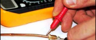
How to check functionality
Use a voltmeter or multimeter , which is set to mV. At the connection, remove the nut that presses the thermocouple to the solenoid valve socket, and remove the working device of the converter. The working area of the couple is heated so that voltage arises in it. When heated, the flame envelops the conductors; a candle or gas burner fire is suitable for this.
Keep in the flame for 30 - 50 seconds , then the first probe of the tester is applied to the thermocouple box, the second to the output contact. Measure for 40 - 60 seconds, without ceasing to heat the working solder. A working element produces a voltage above 20 mV or 0.02 V , some samples show 50 - 55 mV. If the readings are within these limits, the thermocouple is suitable for use.
Making a thermocouple for a multimeter yourself
A thermocouple, created by yourself, is a sensor that is basically structurally similar to the factory one: two soldered electrodes of different composition.
List of materials, tools:
- Konstantin. Available in old Soviet low-resistance ceramic resistors PEV-10 or similar;
- wire, copper;
- lighters: turbo (“stove”) and regular.
The data receiver can be any digital or analog tester. Using such a TP for a multimeter, you can measure the temperature of the objects under study.
Where to get wire
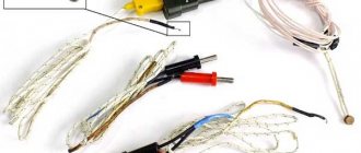
The smaller the wire cross-section, the lower the TP errors, since the very influence of the core array on heat transfer is reduced.
In our example, 2 wires are taken from the following alloys:
- Constantine. We take it from an old ceramic resistor PEV-10. The alloy also contains the foreign analogue 1R00JSMT and similar types of radio components. Some of these radio components are made with nichrome - it will not work;
- copper wires: from the windings of used transformers from household appliances, from cables, for example, twisted pair.
Twisting, welding
We make a twist of 2 wires. Then we weld this end: since the wires are thin, a turbo lighter, popularly known as a “stove,” will do. You should get a round droplet head. The remaining turns must then be untwisted so that there is no short circuit.
We have already described the principle of operation: when heated at the hot junction, that is, the droplet head, a potential difference arises, initiating a small current that will flow through the wiring to the receiver (multimeter). The values of such electricity will characterize a certain temperature.
Other welding methods
Wiring can also be soldered using handicraft welding, for example, using laboratory autotransformers or a car battery. To one pole (“+”) of such a source we connect both ends of the thermocouple, twisted or mechanically connected with wire. To the other we connect the terminal (“−”) connected to a piece of graphite. An electric arc will occur and welding will occur.
The voltage for welding is selected experimentally: they start with low values of 3–5 V and gradually increase to the desired result. The optimal value depends on the metal of the wire, its cross-section, length - it usually does not exceed 40–50 V. Be safe: do not touch bare areas, do not apply too much voltage. For convenience, dangerous segments are insulated with electrical tape, cambric, and ceramic tubes.
A good connection is obtained by heating the wiring with an arc discharge, igniting it between them and a strong (ropa) solution of table salt.
Other alloys for electrodes
Above we showed an example with constantine-copper electrodes. A thermocouple for measuring temperature with your own hands can also be created using wire from other materials (see table above for alloys). Such materials are sold on highly specialized trading platforms, but they are still more difficult to obtain; the most accessible of them are chromel and alumel.
Checking a homemade thermocouple for a multimeter
We connect the electrodes of the assembled sensor to the multimeter in the same way as probes. Then you measure the environment: heat the head with a lighter and observe the tester display. In our case, the multimeter showed a voltage of 50 mV and a current of 5 μA, this is the maximum value for this homemade product.
Calibration
You can calibrate a homemade thermocouple and create a database of which value corresponds to which temperature by lowering the TC into a liquid with a previously known temperature (you will need to heat it up significantly). All that remains is to compare t° with the multimeter readings and write down the digital correspondences.
Accuracy and speed of measurements
The size of the operating error of thermoelements depends on the structure, properties of the alloys, operating conditions and operating environment.
Reasons for inaccuracies:
- heterogeneity of insulation (chemical, presence of inclusions, sagging, internal stresses);
- deformation of electrode elements during manufacturing and operation.
Based on the speed of response to voltage, there are different types of thermocouples:
- high inertia - 210 seconds;
- medium inertia - up to 60 seconds;
- small - up to 40 seconds.
Other homemade products
We have described a method for creating a “bare” sensor; the processing device was already ready - a multimeter. With your own hands, you can create other receivers for such a thermocouple on Arduino, ATmega microcontrollers, as well as amplifiers on similar microcircuits - they will be required, since the EMF is very low.
For homemade products, a popular microcontroller amplifier for thermocouple LM358P/LM358D for the range 0…+70° C.
There are many drawings on the net on how to make a thermocouple for various tasks with Arduino, ATmega microcontrollers and with a digital display.
Feature of the device intended for gas boilers
All thermocouples for a gas boiler are made mostly from non-precious metals. To provide reliable protection from an aggressive external environment, they were placed in a pipe with a movable flange - this ensures reliable fastening of the structure. It has the following components:
- cast, sealed housing with lid;
- Shoes made of porcelain that are attached to the head using screws and floating clips.
The material of manufacture depends on the specific temperature ranges for which the device will be used.
Checking, repairing and replacing the thermocouple
Let's consider malfunctions using the example of a thermocouple in a gas boiler sensor; in such devices it is also called a flame sensor. Along the way, we will reveal some of the nuances of operating thermoelectric detectors, how they are designed, and what such a device consists of.
Signs of damage:
- fading of the wick at the moment when the ignition button is released at the same time;
- the light remains, but after the main burner is ignited, the fuel supply is shut off again and the boiler goes out altogether.
Causes:
- electrodes, hot junction are covered with soot, do not warm up enough. Therefore, the voltage on the circuit drops below the critical minimum required for the device to operate;
- burnout of the protective capsule of the TP;
- broken contacts at the junction point, broken wire;
- the fastening nuts have come loose;
- distortion of the working rod and, as a consequence, poor heating by the igniter;
- The traction sensor is broken or its electrical circuit is broken.
Repair, restoration
Thermocouples are sensitive to any damage and contamination: these factors can reduce the voltage output by the sensor below a critical limit. A typical common cause of poor performance is carbon deposits and soot on the working (heated) segment. To restore it, it is enough to clean it with a soft brush or cotton wool with alcohol. It is important to prevent scratches and mechanical damage. After cleaning, you need to check with a multimeter.
Often the cause of malfunctions is oxidized contacts; they can be cleaned with fine-grain sandpaper, but without excessive force.
Thus, if there is carbon deposits, soot, oxidation, loose or broken contacts, fasteners, etc., then the TP can be repaired. But if deep black dents or burnouts (holes) are found, then such an element is usually not restored. Theoretically, you can build a new protective casing and try to re-solder the ends if they have come apart, but there is no guarantee that such a repair will be of high quality. And from ineffective operation there is a risk of significant deterioration in the service life of the device, the likelihood of emergency situations increases. Almost always, sensors with such critical listed failures are replaced with new ones without hesitation.
Spare parts are sold in specialty stores and service points. Selecting one will not be difficult - just select a detector that is similar or has parameters that are suitable for a specific equipment model. Replacement is simple - snap off the old TP and connect (plug) the new one into the seats.
The only difficulty may be that the device will have to be disassembled, covers removed, assemblies with burners, and so on.
Troubleshooting
If a thermocouple is giving inaccurate temperature readings and it has been checked that there are no loose connections, then the cause may lie either in the recording device or in the thermocouple itself, the recording device is usually checked first, since devices fail more often than thermocouples. Moreover, if the device shows at least some readings, even if inaccurate, then most likely the problem is not the thermocouple.
If the thermocouple is faulty, it will usually not produce any voltage at all and the meter will not give any readings. If there is no reading on the device at all, then the problem is probably the thermocouple. If the thermocouple fails, check its output signal using a device called a millivolt potentiometer, which is used to measure small voltages.
Different types of thermocouples.
FAQ
What does Temperature Class mean?
The ignition temperature is the minimum temperature at which a flammable gas mixture can ignite when in contact with a flame, hot surface or spark. Gases and vapors are divided into classes in which the surface temperature must always be less than that of the mixture. (T1 > 450 °C, T2 > 300 °C, T3 > 200 °C, T4 > 135 °C, T5 > 100 °C, T6 > 85 °C).
What is intercrystalline corrosion?
Intercrystalline corrosion (IC) is a form of corrosion that can occur in most alloys under the right conditions. It is also known as "break grains" or "chrome depletion". Corrosion occurs along grain boundaries.
What is thermo-EMF (or Seebeck effect)?
The Thomas Johann Seebeck effect is that in a closed circuit consisting of dissimilar conductors, a thermo-EMF arises if the contact points are maintained at different temperatures. A circuit that consists of only two different conductors is called a thermocouple or thermocouple.
Which thermometer to choose: with a thermocouple or with a thermistor
The design and principle of operation of a thermocouple in a thermoelectric meter and a thermistor in a resistance thermometer:
It is impossible to unambiguously recommend for all situations which detectors are the best: a thermometer with a thermocouple or with a thermistor (TC, also known as a resistance thermometer), since the environment must be taken into account and compared with the properties of these types of temperature sensors - each has its own pros and cons. We examined them in detail. Now let's describe an example of selection.
First of all, compare the characteristics, compare:
- with the required accuracy. For not particularly demanding purposes, a deviation of 1–2 degrees will not be critical. But for devices that require precision, this parameter is important. In most cases, thermistors are more correct, but this parameter can also be equal for different sensor models, as we see in the table;
- with operating temperature range. Here the TP is undoubtedly better, it covers the scope t° much wider;
- The reaction speed is better with thermocouples, but this is a general rule. This parameter can also be compared (see table);
- thermoelectric converters are better able to withstand vibrations, mechanical loads, and aggressive environments.
It is necessary to determine the best version of the device, taking into account all the nuances and goals. Let's describe this with an example:
- serviced area - a pipeline segment with constantly changing conditions and vibrations. Temperature −200…+300° C;
- the goal is maximum accuracy, and this is the most important condition;
- You can select both types of temperature sensors. At first glance, the TP is more suitable, since it is more resistant to loads and vibration;
- In the end, a thermistor device was chosen, since the goal is accuracy, and this type of sensor has higher accuracy. In addition, a thin-film thermistor was used; this version of the sensor is more resistant to vibration and loads.
Second example:
- environment - reactor, +550...+900° C, low vibration level;
- target - accuracy ±5° C;
- TCs provide consistently accurate measurements, especially at low vibrations, but we must not forget about the t° range. Thermistors should not be used at temperatures above + 850° C. Since our environment is +900, a thermometer with a thermocouple was chosen.
Thermocouple junctions and requirements for them
As a rule, the design of a thermocouple implies the presence of only one junction. Sometimes another one is provided - if the thermocouple needs to be connected to the electrical circuit (directly at the connection points).
In the diagram, the circuit includes three wires - A, B, C. The twisted wires are designated D and E. The junction is presented as an additional one, formed when a thermocouple is connected to the electrical circuit. In the above case, the junction is called cold (free), and the junction designated by the letter E is called hot (working).
Since there is a directly proportional relationship between temperature readings and the voltage that the thermocouple generates, both junctions will generate the same amount of voltage - if the temperature readings on them are the same.
If the junction on the thermocouple is heated, the voltage value begins to increase in direct proportion. Accordingly, a stream of negatively charged particles from the heated junction flows through the second junction, passes through the measuring device and passes back to the hot junction. Accordingly, the device begins to record and demonstrate the voltage difference at these junctions. This difference can be converted both by the operator through special tables into the corresponding temperature values, and by the device itself - depending on what model of thermocouple meter was used.
The requirements for materials for the manufacture of thermocouples and junctions for them are strict, since the operation of these devices is expected in harsh environments:
- The thermoelectromotive force indicators for alloys in thermocouples must be large in order to ensure the necessary accuracy of the measurements. Manufacturers select materials in such a way that the values of thermoelectromotive forces are linearly dependent on temperature values.
- The melting temperatures of substances must be significantly higher than the measured temperature values. The difference is at least 50 degrees Celsius.
- Alloys must be resistant to corrosion. If this requirement cannot be met for one reason or another, then they resort to protection with the help of covers.
- Materials must not change their physical parameters.
- They must have good ductility and strength.
- Finally, the materials must be of low cost to enable the production of thermocouples on an industrial scale.
DIY repair
Being able to fix any thing in the house is a sign of a true owner. But you need to be careful when it comes to gas equipment.
Repair of gas equipment must be carried out by a certified specialist.
But not everything in such a device is gas. Replace burners, burners, clean parts - you don’t need a specialist with permission to do this. First of all, you need to identify the malfunction.
A malfunction of a thermocouple for a gas stove looks like this. The gas only lights up when the button is pressed. As soon as you let it go, the flame goes out. To find out the reason, you need to carefully examine both the device itself and the stove as a whole.
Work to eliminate a thermocouple malfunction begins with turning off the gas supply and inspecting the equipment.
- We disassemble the gas stove.
- Remove the divider from the burner.
- We remove the reflector.
- We check the condition of the thermocouple.
Frequent causes of thermocouple failure are contamination or damage to the sensor.
There are two devices near the gas burner. One of them resembles a spark plug in a car. This is for igniting the stove. The second is a thermocouple. The reasons for its failure may be:
- pollution;
- damage;
- changing the type of gas;
- sensor or valve failure.
If the thermocouple element in a gas stove is dirty, it needs to be cleaned properly. The thermocouple is two pieces of metal and cleaning it involves running fine sandpaper over the surface.
The wiring of the device may be damaged. Scuffs due to improper installation, rodents or pets, other possible causes of damage.
After eliminating the gas control malfunction, you must carefully check the device.
After checking and, if necessary, replacing the wiring, the thermocouple should be connected correctly. Otherwise, the “cold” and “hot” contacts of the circuit will not be in antiphase. All positive wires are connected to the positive terminal. Negative - to negative.
A correctly installed thermocouple is the key to safety when operating gas equipment.
Depending on the type of sensor, the color of the wiring changes. In some cases, the insulation may be double and of different colors. But the primary layer will always remain unchanged. The table shows the colors of the main insulating layer.
| Thermocouple type | Insulation color | |
| Plus | Minus | |
| J | white | red |
| K | yellow | red |
| T | blue | red |
| E | crimson | red |
| S | black | red |
| R | black | red |
It is easy to remember that the color of the negative wire is always red.
How to lay nanoisol
Installation of the material is carried out strictly according to standardized rules. In order to protect the insulation, the vapor barrier material is placed in the interior of the room between the sheathing and the thermal insulation layer.
How to remove a thermocouple from a gas water heater
In order to be able to quickly repair a geyser with my own hands and always have warm water, taking into account the experience of long-term operation of gas water heaters of different models, I always have a set of spare parts on hand. Rubber gaskets, tubes, thermal relay and thermocouple included. Therefore, within half an hour the thermocouple was replaced with a new one, and the column again began to properly heat the water.
The thermocouple is secured to the left on the common bar with the igniter and spark plugs using a nut. Before unscrewing the nut, you need to slightly unscrew the left self-tapping screw holding the bar so that it does not interfere with the wrench turning.
Next, use an open-end wrench to unscrew the nut by rotating counterclockwise until it completely comes off the thread on the thermocouple body. After this, the thermocouple will easily come down from the bar.
In the next step, you need to use an open-end wrench to unscrew the contact screw from the gas-water regulating unit. The screw is located on the opposite side of the gas control knob.
All that remains is to remove two terminals from the thermal protection relay, and the thermocouple, complete with wires, will be removed from the gas water heater.
Installation of a new thermocouple is carried out in the reverse order, and it is desirable that the current-carrying wires do not touch either the internal metal parts of the gas column or the casing after its installation.
Advantages and disadvantages
Like any device, thermocouples have both advantages and disadvantages. Among the advantages of the devices are their low cost, which is due to a fairly simple design, and a long service life. The durability of the devices is explained by the absence of complex components and moving elements subject to friction. An important advantage is the wide range of measured temperatures, as well as easy installation and dismantling of the device. The versatility of thermocouples cannot be ignored, allowing the device to be used both as a flame control sensor and as a thermometer.
Disadvantages include the voltage limit, which is limited to 50 mV. This is one of the reasons for errors in readings that occur when measuring temperatures. The lack of a linear relationship between temperature values and potential difference is also a disadvantage of the device. In addition, the part cannot be repaired, and if it fails, it is replaced with a new one. However, sometimes the thermocouple stops working due to poor contact. To resume boiler operation, you need to remove the thermocouple, clean the conductors and reinstall the device.
Options for installing TSP-N and KTSP-N on pipelines:
Installation type A: For pipelines with a diameter of up to 25 mm, temperature sensors of a special design KTSP-N version 6 (type DS-cable) (TSP-N version 6) with a short immersed part and installed in the corresponding fittings - expanders, which are included in delivery kits for heat meters and flow meters.
Installation type B : In pipelines with a nominal diameter of no more than DN 50 according to GOST R EN 1434-2, installation of temperature sensors in a bend (in an elbow) is also allowed. Temperature sensors on the measuring sections of pipelines can be installed both before and after the flow converters.
Installation type C : If perpendicular (radial installation) of temperature sensors is not possible, then they can be installed obliquely, at an obtuse angle (from 120 to 150 °) to the direction of flow. Moreover, the angles of inclination of the longitudinal axes of the temperature sensors included in the kit to the direction of flow on the supply and return pipelines should differ by no more than three degrees.
Installation type D : For resistance thermometers, perpendicular (radial) installation is the most preferred.
In heat meters, in accordance with the requirements of the Rules for metering thermal energy and coolant on the supply pipeline, resistance thermometers are installed in front of the flow converters, and the distance between them and the flow sensors must be at least 3 DN, and the distance from the resistance thermometers to the nearest local resistance upstream ( including mechanical and magnetic filters) must be at least 5 DN. And if the local resistance is a group of elbows in different planes, a manifold for merging flows, sharp expansions or contractions, or fittings of any type that regulate the flow of the medium, then the distance from such local resistance to the resistance thermometer upstream should be more than 10 D.
To reduce the length of straight sections in front of the temperature sensor after local resistances that cause significant swirling of the flow, flow shapers should be used.
FOR THE AUTHOR'S CERTIFICATE (1)911102
Union Soviet to
Resnubpik. (61) Additional to auto. said-vu (2) Declared 040779 (2>) 2789973/22-02 (5!) M. Cl. with the addition of application No. 2999393 f 22-02
USSR and affairs of theories and discoveries (23) Priority
Published 070382. Bulletin No. 9 (53) UIC 536.532 (088. Date of publication of the description 070382
Yu.V. Malkov, A.S. Kozhevnikov, A. Romanovskaya, G.A. Kadyshev and A.G. Zayev
Cherepovets Order of Lenin Metallurgical Plant named after. 50th anniversary of the USSR
I (72) Authors of the invention (7l) Applicant (4) METHOD OF INSTALLING THERMOCOUPLES
The invention relates to temperature measurement, mainly in heating furnaces with double-sided heating.
There is a known method of installing thermocouples for measuring the temperature of the medium in heating furnaces containing lower and upper zones and a system of heating devices. Thermocouples are located in the upper zones in the roof and in the lower zones in the side wall of the furnace.
With the indicated arrangement of thermocouples in the lower zones of the furnace, the temperature of the environment near the side masonry of the furnace is recorded, and it is impossible to obtain a reliable temperature measurement in the volume of the zone, especially on furnaces with a hearth width of more than 6 m due to the large size of the zone (15.
The disadvantage of the known method of installing thermocouples in a heating furnace with walking beams is that thermocouples for measuring the temperature of the medium in the lower zones, located in the masonry of the side walls on the side of the burners, do not provide accurate measurement of the temperature of the medium and, therefore, high-quality regulation of the temperature regime in the zones due to their low sensitivity to changes in gas temperature in the volume of the zone when fuel consumption changes. This is explained by the direct influence on the thermocouple of the torch of the nearest burner and the cooling effect of the air entering the working space of the furnace along the periphery of the burner. Besides,. with such installation of thermocouples in the lower zones and a staggered arrangement of metal/on support beams, the temperature level of the upper zones influences the side thermocouples installed in adjacent lower zones.
Due to the indicated shortcomings in automatic temperature control. temperature in the furnace is underheating
3 and overheating of the metal, which requires switching to manual control of the furnace.
The purpose of the invention is to increase the accuracy of measuring the temperature of the medium and to ensure control of the required temperature difference along the length of the slab.
This goal is achieved by the fact that according to the method of installing thermocouples in the heating furnace in the upper and lower zones of preliminary and final heating of the furnace, thermocouples are enclosed in lined thermoblocks and installed in the lower zones of preliminary and final heating on the hearth along the axis of the furnace, 15 at In this case, the thermocouple junction is located (at the level of 0.3-0.8 of the height of the lower zone.
In addition, thermocouples in the final heating zone are placed across the furnace at a distance equal to
3.5-7.54 from the width of the hearth relative to the axis of the furnace, and the working junctions isolate them from each other.
The thermocouple junctions are located at a level of 0.3-0.8 of the height of the lower zone. This is due to the fact that at a height less than 0.3 of the height of the lower zone, the thermocouple reading is affected by the temperature of the hearth masonry. At a height of more than 0.8 times the height of the lower zone, the reading of thermocouples is affected by the heated metal. To obtain uniform heating of the slabs along the length, thermocouples for measuring the temperature of the medium in the lower heating zones of the furnace are located on the hearth along the axis of the furnace. This eliminates the influence of the burner torch and the air entering along the periphery of the burners on the thermocouple readings, and the thermocouple measures the average temperature in the furnace zones.
To ensure a given temperature difference along the length of the slab in the zone
i$ final heating independent temperature measurement simultaneously at two points along the width of the furnace and the possibility of separate regulation of different temperature conditions according to
S0 width of the furnace thermocouples are located on the hearth at a distance from each other equal to 7-15 from the width of the furnace hearth, and their working junctions are separated from each other by a refractory partition and facing in opposite directions in the opposite direction.
55 instructions for installing appropriate side heating devices. Side partition eliminates exposure
4 per burner thermocouple. the opposite side. If the thermocouples in this chamber are installed at a distance,. greater than 15 times the width of the hearth, the thermocouple falls into the area of influence of the burner torch.
When thermocouples are located at a distance less than 7/5 of the width of the furnace bottom, the temperature of the medium is measured not in the corresponding zone along the width of the furnace, but some average temperature of two zones, which eliminates the possibility of heating the slab with a given temperature difference along the length.
In fig. Figure 1 shows a heating furnace with installation of thermocouples, longitudinal section; in fig. 2 - the same, cross section; in fig. 3 - a thermocouple enclosed in a thermoblock for monitoring and regulating the temperature of the medium in the lower heating zones. oven areas; in fig. 4 - thermocouples enclosed in a thermoblock, separated by a partition, to control and regulate the temperature in the final heating zone.
The method is carried out as follows.
Along the width of the furnace 1 (Fig. 1 and 2) there are several movable 2 and fixed 3 (Fig. 2) longitudinal support beams. Heated slabs 4 and 5 are located on fixed beams, perpendicular to them. Transportation of slabs into the furnaces is carried out using movable (walking) beams 2.
When the furnace operates with automatic thermal control, the metal, moving from the landing window 6 to the final heating zones Vll u V!!I, is evenly heated in the heating zones !-H! to the set temperature. Uniform heating of the metal is ensured by combustion of fuel in fuel-burning devices
7 installed in the lower zones. lV, Ch and Vl in the side walls, and reliable indicators of thermocouples
8, regulating the change in heat. THOUGH STATE OF THE ZONES. The reliability of the readings of the thermal state of the zones is achieved by installing thermocouples on the bottom along the axis of the furnace, their perception of the average heat flow of gases moving through the center of the furnace, and eliminating the influence of individual fuel-burning devices on the thermocouple readings 7, 5 91
When metal arrives in eons
Vll-Vill final heating, the permissible temperature difference along the length of the heated slab is achieved by supplying different amounts of fuel to the left 9 and right 10 parts of the zone and independent temperature measurements of the left and right parts of the thermal zone. pairs 11 installed on the bottom of the furnace and separated from each other by a refractory partition 12, eliminating interference between the left 9 and the right
10 parts of the zone. This allows you to automatically maintain a given level of temperature difference along the length of the slab.
When heating slabs 5 with their staggered arrangement on the support beams, the influence of the temperature level of the upper zones l, lll, V u Vll on the readings of thermocouples 8 and 11 of the lower zones is eliminated, since the latter, “located on the hearth, are constantly blocked from the upper zones by the slabs. Consequently, placing thermocouples in the lower zones of the furnace bottom increases the measurement accuracy, allows you to obtain the required quality of heating of the slabs, and automatically control the heat. mode and in the lower zones, as well as improve the economic performance of the furnace.
1. The method of installing thermocouples in a heating furnace in the upper and lower zones of preliminary and final heating of the furnace, which means that, in order to increase the accuracy of temperature measurement on calls, thermocouples are enclosed
The invention relates to the field of electric heating, namely electrical installations of conveyor-type radiation heating, and can be used in industry for heat treatment of objects of various physical natures
The thermocouple is the main control and measuring module in non-volatile gas boilers. If it malfunctions, it is impossible to supply gas to the burner, it will not be possible to ignite the boiler, and attempts to bypass its operation are simply unsafe. Fortunately, the design of the thermocouple and the algorithm for replacing it are quite simple; with minimal skills, you can fix the problem yourself, in some cases even without replacing the module.
Read in the article
What types of thermocouples are there?
According to the number of sensitive elements of thermal resistance there are:
— with one element (standard version); - with two sensitive elements.
| Number of sensing elements | Electrical circuit of the sensor |
| One | |
| Two |
According to the design of the switching head, thermocouples are:
— with a plastic head (default version); — with a metal head (when ordering, the MG code is added at the end of the sensor brand); — with an enlarged plastic head (when ordering from a brand, code L is added to the model); — with an enlarged metal head (when ordering in a brand, code L is added to the model and code MG is added at the end of the sensor brand). The enlarged head is used to integrate an NPT current normalizing transducer into the sensor, which turns a conventional thermocouple into a temperature transducer with a current output of 0..20 or 4..20 mA.
| Design | Standard version | Increased performance | With built-in NPT-3 |
| Plastic heads | |||
| Metal heads | For models 015-105, 185-215, 265 (default delivery) | ||
| For models 115-165, 225, 275, 285, 295, 365 (default delivery) | |||
| For models 115-165, 225 - with a latch (delivery upon request) |
Types of temperature sensors for gas
Thermocouples of gas stoves differ in the alloy of conductors and the type of connection to the valve. And the main thing here is that each manufacturer of gas-powered equipment uses its own versions of electromagnets with different connection connectors.
In most cases, it is impossible to move the thermocouple gas control sensor from one tile to another.
The thermocouple must correspond to the model of the gas stove; installing a “left” control device is prohibited for safety reasons
The following alloys and metals are used to create thermocouples:
- constantan + chromel;
- copper + constantan;
- copper+copel;
- nisil + nichrosil;
- alumel+chromel;
- constantan+iron;
- chromel+copel;
- platinum+platinum;
- tungsten+rhenium.
The accuracy of the device and its operating temperature range depend on the alloys used. For example, a chromel-alumel thermocouple is designed to operate at 0–1100 0C, an iron-constant thermocouple at 0–700 0C, and a platinum-platinum-rhodium thermocouple can withstand heating up to +1700 0C.
Household gas stoves usually use thermocouple sensors made of alumel and chromel or constantan and iron. They are inexpensive and quite suitable for the temperature conditions of a gas cooktop.
Seebeck effect
The operating principle of a thermocouple is based on this physical phenomenon. The bottom line is this: if you connect two conductors made of different materials (sometimes semiconductors are used), then current will circulate through such an electrical circuit.
Thus, if you heat and cool the junction of the conductors, the potentiometer needle will fluctuate. A galvanometer connected to the circuit can also detect the current.
If the conductors are made of the same material, then the electromotive force will not arise, and accordingly, it will not be possible to measure the temperature.