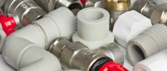
What is it and what is it for?
This device is a special type of safety valve installed in pipeline systems to protect against destruction that occurs when there is excess pressure in them.
Externally, it does not differ from bypass valves, which maintain constant pressure in the system by continuously removing excess fluid. But unlike them, it is triggered in the system periodically, only when the pressure rises above the established norm.
Principle of operation
The principle of operation of the mechanism is based on detecting hydrodynamic pressure mechanically and resetting it to the specified parameters. Structurally, this is implemented as follows: in a metal case there is a rod with a diaphragm valve, secured in a certain position by a spring.
As the pressure increases, the spring compresses, the membrane rises and part of the coolant is discharged. After the coolant parameters are normalized, the spring expands and closes the discharge pipe.
Control can be implemented mechanically or automatically. For proper operation of the device, it is important to exclude the installation of shut-off valves or other equipment in the control section of the pipe.
Purpose and scope of application
The valve is used to protect premises and equipment from excess pressure of the medium transported through pipes:
- heating systems - to remove excess coolant volume from heating devices resulting from thermal expansion;
- water supply - to reduce the risk of water hammer;
- ventilation - ensures air movement only in a given direction;
- gas supply, compressed air supply, fire extinguishing and other types of pipeline structures - in case of emergency situations.
Design and principle of operation of the pressure regulator
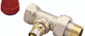
A gas pressure regulator or pressure reducing valve is designed to reduce the pressure in the line diverted from the main line and maintain this pressure at a constant level.
Pressure regulators are used to maintain the pressure required for the operation of pneumatic, gas or other equipment.
For example, pressure reducing valves are installed on gas cylinders and allow you to adjust the required pressure in the line discharged to the consumer. Reducing valves installed on cylinders are often called pressure reducers, since they reduce or reduce the pressure in the outlet line (reduction - reduction, reduction, reduction).
Controls and technical characteristics
The simplest models of low-flow blast valves, used mainly for domestic engineering systems, are manually controlled mechanically. Products installed on large-section production pipelines can be controlled remotely.
Depending on the material of manufacture and design features, the devices are endowed with different technical characteristics.
The characteristics of several models of emergency pressure relief valves designed to work with gaseous substances are presented in the table.
Check valve
A check valve (return valve) is a device that allows compressed air to flow in only one direction. Structurally, it is assembled (see figure) in a metal case (item 3), inside of which the following are located:
- internal shutter (item 6), blocking the inlet;
- a spring (pos. 4) pressing the rubber ring (pos. 5) to the bolt seat;
- inlet fitting (pos. 7);
- plug (item 1) with a sealing gasket made of cardboard (item 2) (the plug makes it possible to disassemble the return for repair or maintenance).
On a note! The check valve has a branch for connecting it to the receiver and a small branch for connecting a pressure switch.
Operating principle
The reverse action valve works as follows. Passing through the outlet valve of the piston cylinder, the compressed air enters the return pipe through the inlet fitting (pos. 7). Having reached a certain pressure, the air lifts the internal shutter (pos. 6) and passes through the cavity in the housing (pos. 3) into the storage tank of the receiver. When the compressor is turned off, the spring (item 4) returns the internal shutter to its place, blocking the path of air from the receiver back into the piston cylinder.
Varieties
On the domestic market you can find compressors with returns made of three different materials: aluminum, plastic and brass. At the same time, the aluminum part differs from its analogues in its high reliability and durability. It is built inside the air duct that connects the piston cylinder to the receiver, and is capable of operating under high temperature conditions (up to 200°C). Whereas a plastic return line is installed in budget models operating at a low temperature of the working environment. As for valves made of brass, they are widely used. Such return valves are quite reliable and perfectly maintain their performance characteristics in cases where the air temperature during compression does not exceed 140°C.
Recommendations for selection
If the compressor return valve fails, it is not difficult to replace it with a similar one
However, before you buy a new valve, you need to pay special attention to the diameter of the threads cut on the outlets of its body. After all, the connecting dimensions of the return, compressor and receiver may differ from each other
Advice! When going for a new check valve for your compressor, do not forget to take the failed part with you. This will greatly facilitate the selection procedure for a new node.
It is also necessary to take into account the technical characteristics and operating conditions of the compressor. After all, there are valves that are not designed to work with high-pressure compressor equipment. In addition, when the working medium heats up to a high temperature during compression, the use of plastic returns is impractical - it is better to purchase a unit in a metal case, which is mounted inside the air duct connecting the compressor and the receiver. It will not be superfluous to purchase a collapsible design - this will allow you to buy the appropriate repair kit in the future and fix the return fault yourself, replacing the failed parts with purchased spare parts.
Making a check valve yourself
In cases where it is not possible to purchase a new check valve to replace a faulty one, you can make it yourself from scrap materials. For this you will need:
- female tee;
- spring;
- 2 couplings with external thread, the diameter corresponding to the internal thread of the tee;
- a ball whose diameter is larger than the size of the internal hole in the coupling;
- a metal plug with an external thread that matches the internal thread on the tee.
The valve is assembled in the following sequence: first, the coupling is screwed into one of the branches of the tee, then a ball is inserted into the tee on the other side, and then the plug is screwed in, pressing the ball with a spring.
There are several practical tips for making a return line.
- It is best to take the ball from an old computer mouse - it has a rubberized surface that will fit more tightly to the edges of the hole.
- You can also use a regular piece of pipe of suitable diameter as a body. True, in this case you will have to drill a side hole in it, weld another bend and cut threads at all ends.
- The spring must press the ball with a certain force and in no case should it be weakened.
Connection type
Based on the type of connection or connection to the pipeline, valves are divided into:
- flanged products - equipped with flange plates at each outlet and connected to mating flanges at the ends of the pipes using bolts;
- threaded - imply the presence of outlet pipes with external threads;
- welded - attached to the gas pipeline by welding and ensure 100% tightness.
Recommendations for use
When operating the air pressure relief valve, follow the instructions in the manufacturer's user manual.
The valve must be kept clean and must not be exposed to dust, moisture or other contaminants. It is also unacceptable to paint the valve with a brush or spray gun. This can lead to contamination of the outlet pipe and failure of the device.
Periodically, at least once a month, the valve should be tested for maximum pressure. If for any reason the valve does not operate during testing, operation of the unit should be stopped until the problems are clarified and eliminated.
Such tests should also be carried out after any removal of the valve from the unit, even if the dismantling was not associated with its repair or replacement.
Device
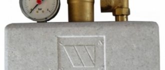
The standard design of an overpressure relief valve includes:
- cast body made of stainless steel, brass or bronze;
- plate - the main shut-off element that blocks the flow of the medium;
- plate lever - used to control this part;
- safety lever - performs protective functions if the main locking element does not work;
- tuning knob;
- springs;
- additional details (control buttons, counters, dials, barometer, etc.).
What is it needed for?
The function of the valve is to discharge excess hot water in the working tank of the heater. The expansion of water creates high pressure, threatening the integrity of the device.
The valve automatically drains a certain amount of water, bringing the total volume to the nominal value. This allows you to preserve the heater, protect equipment and people from contact with hot water.
Excess volumes of water are discharged through a special pipe connected to a drainage system or a special receiving tank.
Types and designs
Relief valves are divided into two main groups:
- direct action, opening only under the influence of pressure from the internal environment. These include devices used to prevent excessive pressure build-up in oil and fuel systems;
- indirect acting, using an external pressure source. They are more suitable for liquid and air systems.
Depending on the design features and principle of operation, they are divided into four types.
With remote sensor
The device is equipped with a spring mechanism and a rod driven by main or backup bellows. When the water overheats, they are affected by a heat-sensitive liquid rising through the capillary tube from the sensor flask.
When the device is triggered, the rod opens the plate for the movement of coolant. There are two pipes in the valve body to the supply line and to the sewerage system to discharge excess water.
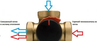
Combined with make-up systems
They are a type of safety valve in heating systems that can perform 3 functions at once:
- dump overheated coolant from the boiler tank based on a signal from an external sensor;
- effectively cool the heat generator;
- automatically recharge the heating system with cold water.
The rod of such a product is equipped with two plates that can simultaneously open 2 passages: one for discharging boiling coolant, the other for supplying cold water.
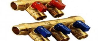
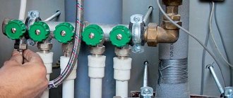
The models presented in the next photo have a triple output. They are built into the pipeline in front of the heating device or boiler. The lower pipe is used to discharge the medium; two upper pipes are used to connect the water supply and make-up lines.
Spring
In such devices, the spool is driven by the compression force of the working spring. The settings of the same valve can be adjusted by replacing different types of springs included in its kit.
A number of models have an additional lever built into the body that performs manual detonation. With its help, you can manually purge the valve to check its general technical condition or release part of the working fluid.
Since the spring in most cases is exposed to the internal working environment, for devices that work with aggressive substances, it is covered with a protective layer of polymer. Such product models have stem seals like a stuffing box or bellows device.
Lever-load
The main unit of this type of valve mechanism is a lever with a weight suspended on it. The operation of the device is affected by the weight of the load and the length of the lever arm to the place where it is placed. The more massive it is and the farther it is from the rod, the higher the pressure the relief valve is triggered.
To ensure complete sealing of large seats, it will be necessary to use a heavier load, and this can lead to quite a high level of vibration of the entire device. In such cases, valves are used in which the medium discharge cross-section is formed by two parallel seats. The body of such a device also contains two shutters that operate in parallel. This design reduces the weight of the weighting material and the length of the levers and has a positive effect on increasing the rate of operation of the unit.
How to choose a relief valve
Of course, in terms of purchase and installation costs, a traditional blasting valve will be cheaper than temperature devices. It will easily protect a closed heating system connected to a gas, diesel or electric boiler, because in the event of an accident they stop heating almost instantly. Another thing is a heat generator using wood and coal, which cannot go out immediately.
To successfully select a thermal relief or overpressure valve, follow these guidelines:
- When using any energy carriers other than solid fuel, feel free to buy a regular blasting device.
- Study the documentation of your heat source or boiler (depending on what needs to be protected) and select safety fittings according to the maximum permissible pressure indicated therein. Most heating equipment is designed for a limit of 3 Bar, although there are exceptions - Lithuanian Stropuva boilers can withstand only 2 Bar, and some Russian units (among the inexpensive ones) can withstand 1.5 Bar.
- To effectively cool wood-burning heat generators in the event of an accident, it is better to install one of the thermal relief valves. Their maximum operating pressure is 10 Bar.
- In open systems with a TT boiler, pressure relief is useless. Select a safety product that operates at a coolant temperature of 95–100 °C, suitable for your unit and recharge method.
Advice. Refrain from purchasing cheap safety valves from China. Not only is it unreliable, but it also leaks after the first explosion.
In addition to models with fixed settings, there are valves with adjustable settings on sale. If you are not a heating professional, then you should not buy them, and there is no particular need.
Advantages and disadvantages
The use of excess pressure relief valves allows you to extend the service life of pipelines by eliminating the occurrence of water hammer and releasing pressure in the system when it increases to critical values. The advantage of these devices is also:
- simplicity and reliability of design;
- easy installation and further maintenance of the device;
- low local resistance values;
- high throughput.
The disadvantages include:
- low wear resistance of sealing gaskets that ensure tightness on the rod;
- unsuitable for working with media containing solid particles.
How to choose a boiler pressure relief valve
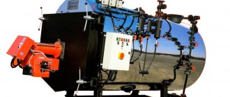
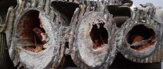
If you do not limit the heating of water in the boiler, it will boil and turn into steam, which will lead to a critical increase in pressure in the heating network. This is followed by a rupture of the pipeline or water jacket of the heat generator. To avoid the described emergency situation, a safety valve for heating is installed at the boiler outlet, releasing excess pressure from the system. Our publication is devoted to the selection and installation of this important element.
Tips for choosing
When choosing a device, you need to focus on:
- its compliance with the maximum permissible pressure in the system;
- pipeline section;
- ambient temperature;
- throughput and height to which the spool is capable of rising;
- type of working substance.
If it is intended to discharge the working medium directly into the air, then a valve with an open type design can be used. For liquid systems, you will need a closed type device, preferably with a special spout for connecting the discharge water drainage hose. The product body must be marked with the direction of the medium flow, which will significantly facilitate installation work.
Check valve
A check valve (return valve) is a device that allows compressed air to flow in only one direction. Structurally, it is assembled (see figure) in a metal case (item 3), inside of which the following are located:
- internal shutter (item 6), blocking the inlet;
- a spring (pos. 4) pressing the rubber ring (pos. 5) to the bolt seat;
- inlet fitting (pos. 7);
- plug (item 1) with a sealing gasket made of cardboard (item 2) (the plug makes it possible to disassemble the return for repair or maintenance).
Operating principle
The reverse action valve works as follows. Passing through the outlet valve of the piston cylinder, the compressed air enters the return pipe through the inlet fitting (pos. 7). Having reached a certain pressure, the air lifts the internal shutter (pos. 6) and passes through the cavity in the housing (pos. 3) into the storage tank of the receiver. When the compressor is turned off, the spring (item 4) returns the internal shutter to its place, blocking the path of air from the receiver back into the piston cylinder.
Varieties
On the domestic market you can find compressors with returns made of three different materials: aluminum, plastic and brass. At the same time, the aluminum part differs from its analogues in its high reliability and durability. It is built inside the air duct that connects the piston cylinder to the receiver, and is capable of operating under high temperature conditions (up to 200°C). Whereas a plastic return line is installed in budget models operating at a low temperature of the working environment. As for valves made of brass, they are widely used. Such return valves are quite reliable and perfectly maintain their performance characteristics in cases where the air temperature during compression does not exceed 140°C.
Recommendations for selection
If the compressor return valve fails, it is not difficult to replace it with a similar one
However, before you buy a new valve, you need to pay special attention to the diameter of the threads cut on the outlets of its body. After all, the connecting dimensions of the return, compressor and receiver may differ from each other
It is also necessary to take into account the technical characteristics and operating conditions of the compressor. After all, there are valves that are not designed to work with high-pressure compressor equipment. In addition, when the working medium heats up to a high temperature during compression, the use of plastic returns is impractical - it is better to purchase a unit in a metal case, which is mounted inside the air duct connecting the compressor and the receiver. It will not be superfluous to purchase a collapsible design - this will allow you to buy the appropriate repair kit in the future and fix the return fault yourself, replacing the failed parts with purchased spare parts.
Making a check valve yourself
In cases where it is not possible to purchase a new check valve to replace a faulty one, you can make it yourself from scrap materials. For this you will need:
- female tee;
- spring;
- 2 couplings with external thread, the diameter corresponding to the internal thread of the tee;
- a ball whose diameter is larger than the size of the internal hole in the coupling;
- a metal plug with an external thread that matches the internal thread on the tee.
The valve is assembled in the following sequence: first, the coupling is screwed into one of the branches of the tee, then a ball is inserted into the tee on the other side, and then the plug is screwed in, pressing the ball with a spring.
There are several practical tips for making a return line.
- It is best to take the ball from an old computer mouse - it has a rubberized surface that will fit more tightly to the edges of the hole.
- You can also use a regular piece of pipe of suitable diameter as a body. True, in this case you will have to drill a side hole in it, weld another bend and cut threads at all ends.
- The spring must press the ball with a certain force and in no case should it be weakened.
Rules for installation and operation of the device
Installation of the product on the pipeline must be done with sealing gaskets without distortions. The working substance passing through the valve must be free of mechanical inclusions and abrasive particles. It is advisable to install a mesh filter of the appropriate diameter at the inlet to the system. Installation of the device with a spring mechanism is carried out strictly in a vertical position, with the lid facing up. For the lever included in the design of the lever-load device, it is necessary to ensure a horizontal position. It is not recommended to place shut-off elements in the form of taps, gate valves, or levers in front of a relief valve.
To eliminate excess liquid, it is necessary to install an additional outlet used to drain water into the sewer pipeline or return pipe.
If the system includes a gravity device, the valve must be installed at the highest point.
During operation, it is necessary to periodically inspect the device, since in products with a spring mechanism, displacement of the plate towards the walls of the housing may occur.
Required tools and materials
To install the valve you will need:
- adjustable wrench;
- fum - ribbon or tow;
- special paste for sealing joints.
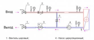
Connection diagram
For example, let's look at the installation diagram of the device in front of the hot water heater in the apartment.
Work progress
Each product designed for releasing excess pressure is equipped with installation instructions, which should be carefully studied before starting work. Before installation, you also need to disconnect the water heater from the network and drain the water from it. The valve must be placed on the cold water supply up to the shut-off valve. The valve installation sequence is as follows:
- marking the installation site;
- removing a part of the pipe of a size corresponding to the length of the device body;
- threading the ends of pipes:
- covering the threaded part with tow or fum tape;
- screwing the valve onto the pipe thread;
- connecting to another pipe a pipe leading to the sewer system.
- tightening the threaded connection using an adjustable wrench;
- sealing the joint with a special paste;
- setting up the device in accordance with the passport values (if necessary).
Installation Rules
In closed heating systems, the safety valve is installed at the highest point of the supply circuit.
There should not be any functional elements (valves, valves, gate valves) between it and the boiler. A mandatory requirement for installing the device is a strictly vertical position. Installation even at a slight angle will result in water leakage.
A discharge hose is connected to the valve's discharge pipe, which is directed into the sewer. It is advisable to choose a location for installing the device to ensure easy access to it in case of need for maintenance or replacement.
Expert advice
- A blasting device with standard technical characteristics allows water to pass through even at low pressure levels when clogged. The problem can be solved by cleaning the body parts. To do this, the product must be dismantled and placed in a container with vinegar for 2 - 3 hours. Then rinse it with water until completely clean and install it in its original place, lubricating the connection area with alcohol.
- If the valve continues to leak even after cleaning, then most likely the rubber gasket resting on the seat is clogged with debris. It is easier to replace such a part than to clean it without deformation. Replacing the valve on the supply pipeline to the boiler can be seen in the video:
- A number of consumers quite reasonably doubt the durability of shut-off valves with plastic parts. They actually have a shorter service life, so it’s better to immediately buy ones with metal components. Such products are on average 100 - 150 rubles more expensive, but they last much longer.
- You cannot simply turn off the device, even if it is leaking. A huge number of heating boilers have failed precisely after installing the plug.
Why is the emergency valve leaking?
If a puddle appears under the safety valve, it is necessary to inspect the system. If you do not pay attention to this symptom for a long time, the boiler may even explode. So let’s immediately check the possible reasons:
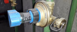
- The pressure in the expansion tank is too low and it cannot cope with the task. Check the pressure in the membrane tank. To do this, there is a spool in the upper part; we connect a pressure gauge to it and look at the readings. It should be 0.2-0.5 bar less than the operating pressure of the system. If it’s too low, take a pump and pump it up through the same spool.
- The membrane in the membrane tank is damaged. The solution is to change the membrane or install a new tank.
- The membrane tank is smaller than required for the system (10% of the system volume). If the volume is really small, we either install a second tank or change it to a larger one.
- The coolant overheats (boils). To solve the problem, circuit solutions are required; circuit modernization is required. A more gentle but temporary solution is to reduce the intensity of combustion.
If you do not pay attention to the dripping blast valve, the boiler may burst - The emergency valve is clogged. Sometimes deposits appear on the seat or rubber gasket. This could be debris brought in by the flow of coolant, or it could be the result of constant leaks. In the first option, we simply remove the debris and put the device in place. In the second case, the valve will have to be replaced. Plaque forms when a little fluid is released and it dries out, and this is abnormal operation of the system (or valve). The solution is replacement. If the new one is leaking, you need to check all the options in the list above.
- Incorrectly set actuation pressure on the valve. In this case, you need to check at what pressure your safety device actually operates. To do this, by lowering and increasing the pressure in the system, you can determine the real response threshold. If the model is adjustable, adjust the settings. If the response value is fixed, you will have to buy another device.
Once again, we draw your attention to the fact that a puddle under the emergency valve is a cause for concern and a signal that it is necessary to inspect the system components responsible for stabilizing the pressure.