South Korean gas boilers of the Master Gas Seoul brand are structurally complex functional devices with rich technical equipment. Compact units are literally crammed with devices that ensure stable operation of the equipment and automate the process. All system components are important and interconnected, but any one of them can fail.
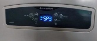
Master Gas boiler error codes will help you find out about the occurrence and cause of the malfunction. The alphanumeric combinations that appear on the display will tell you where the violation occurred and will allow you to quickly decide what should be done to eliminate it. It is extremely important not to waste time when restoring the unit’s functionality. Do you agree?
We will tell you how boiler malfunctions are coded by the manufacturer. We will tell you what actions need to be taken to correct the situation. From the article we presented, you will learn what repairs are needed to restore the unit and which of the shortcomings in the work can be eliminated with your own hands.
Faults and error codes of the gas boiler Ariston, Protherm, Baxi
The microprocessor control and monitoring system of a modern gas boiler detects a malfunction and displays an error code indicating a particular malfunction in the operation of the boiler components and assemblies.
The boiler control system reacts differently to the occurrence of a malfunction. Depending on the possible consequences of the malfunction:
- The operation of the boiler is immediately blocked in an emergency. The boiler turns off. It is necessary to eliminate the malfunction and restart the boiler using the “Reset” button. The boiler settings return to factory defaults.
- The boiler operation stops abnormally, but is not blocked. After the problem is resolved, the boiler will automatically continue to operate with the previous user settings.
- There are errors - warnings that do not require immediate intervention, in which the boiler operation does not stop.
Conclusions and useful video on the topic
The following video will introduce you to the rules for servicing South Korean boilers of the Master Gas Seoul brand:
The rules and specifics of deciphering errors are extremely useful information that allows you to quickly respond to all possible violations in the operation of the boiler. Still, the owner will be the first to face all types of failures. It is up to him to decide on further actions.
Do you want to share your own experience in deciphering Master Gas boiler errors and promptly eliminating the problem? Do you have useful information not listed in the article? Please leave comments in the form below, ask questions and post thematic photos.
Error codes for gas boilers Protherm Panter and Gepard versions 18 and 19
F00 - Malfunction of heating temperature sensor (NTC2, NTC5): flow sensor at the outlet of the heat exchanger (NTC2) is disconnected - Check the sensor connections;
Malfunction of the NTC sensor of the primary heat exchanger. Measure the resistance of the NTC sensor. In the “Electrical part” section there is a table of correspondence between temperature and resistance of NTC sensors, with which you need to compare the measured value. If the resistance of the NTC sensor matches its temperature, the connecting wiring must be checked. The location of the primary heat exchanger NTC sensor is shown in the Components section. After eliminating the cause of the malfunction, there is no need to press the RESET button.
F01 - Malfunction of the heating temperature sensor (NTC2, NTC5): the return sensor at the inlet to the heat exchanger (NTC5) is disconnected - Check the sensor cables.
Malfunction of the NTC sensor on the return OB line. Measure the resistance of the NTC sensor. In the “Electrical part” section there is a table of correspondence between temperature and resistance of NTC sensors, with which the measured value must be compared. If the resistance of the NTC sensor matches its temperature, the connecting wiring must be checked. The location of the NTC sensor on the return exhaust line is shown in the Components section. After eliminating the cause of the malfunction, there is no need to press the RESET button.
F10 - Malfunction of the heating temperature sensor (NTC2, NTC5): short circuit of the supply sensor (NTC2) - Check the sensor (specifications in the "Measurements" section).
Short circuit of the NTC sensor of the primary heat exchanger. In this case, the sensor clearly shows an incorrect value compared to that indicated in the table. The location of the primary heat exchanger NTC sensor is shown in the Components section. After eliminating the cause of the malfunction, there is no need to press the RESET button.
F11 - Malfunction of the heating temperature sensor (NTC2, NTC5): short circuit of the return sensor (NTC5).
Short circuit of the NTC sensor on the return OB line. In this case, the sensor clearly shows an incorrect value compared to that indicated in the table. The location of the NTC sensor on the return line is shown in the Components section. After eliminating the cause of the malfunction, there is no need to press the RESET button.
F13 - Boiler sensor fault (NTC1): sensor short circuit: shunt instead of sensor on X16.
F20 - Overheating fault (97˚C measured by heat flow sensor) (NTC2, NTC5): no heating water flow through the device circuit - Make sure the pump is working properly
Unlock the pump
- Make sure the heating valves are open as well as the bypass valve
- Check the condition of the plate heat exchanger if the fault occurs in hot water mode
- Check the condition of the thermal filter.
The boiler has entered an overheating state. The emergency thermostat tripped and shut down the boiler. By cooling to a temperature of 80 °C and pressing the RESET button, the boiler can be resumed. If overheating occurs again, it is necessary to check the normal operation of the coolant pump and the condition of the primary heat exchanger.
Other reasons may be a malfunction of the NTC sensor of the primary heat exchanger, a severely clogged external filter on the return pipe, or a violation of the hydraulic and thermal conditions in the heating system itself.
F22 - There is no water in the installation (pressure < 0.3 bar) (Cp):
- Heating system leaking
- PSK leakage
Expansion tank defect:
- Fill the system
- Check the expansion tank
- Make sure there are no leaks
There is insufficient water in the boiler. For safety reasons, the boiler switched off because... the exhaust gas pressure became critically low (about 0.29 bar). As soon as the water pressure reaches 0.31 bar, the boiler will automatically start working. When filling the boiler with water, in this case it is not necessary to press the RESET button.
F23 - The maximum difference between the flow and return temperatures has been reached (35 oK) (NTC2, NTC5): Problem with water circulation, (low flow) -
- Check the thermal output and return sensor connector
- Check pump speed
- See also solution for fault F20
Either there is not enough water in the system, or the water flow is very low. The error indication appeared due to a large temperature difference (more than 35 °C) between the NTC OM sensors on the supply and return pipelines. After eliminating the cause of the malfunction, you must press the RESET button.
F24 - Water circulation malfunction (temperature rises faster than 10 oK/sec) (NTC2, NTC5): Poor pump operation or low water pressure -
- See fault F.20, or:
- Heating taps are closed, bypass does not work
- Pump disabled or blocked
Excessively rapid increase in temperature. Check the position of the shut-off valves under the boiler, the circulation pump and the extract air filter. After eliminating the cause of the malfunction, you must press RESET.
F25 - Only for boilers with an open combustion chamber. As a result of the draft failure, the flue gas thermostat overheated and, as a result, an emergency shutdown of the boiler occurred. Check the chimney and whether it has the required draft.
Troubleshooting tips:
- Check the chimney for tightness of seams and connectors, for compliance with the manufacturer's recommendations for length and diameter, for the absence of obstacles in the smoke channel (clogging, icing), for blowing and backing of wind draft (for the location of the chimney head relative to the roof)
- Check the free flow of air into the room where the boiler is installed. There must be an inlet from the street or from an adjacent room with windows.
- Check the functionality of the exhaust gas thermostat.
For a boiler with an open combustion chamber, if the air comes directly from the street, then a supply ventilation opening of 8 cm2 per 1 kW of boiler power is sufficient, but not less than 200 cm2. If the air supply comes from an adjacent room of the building, then the minimum size of the supply ventilation opening should be determined at the rate of 30 cm2 per 1 kW of boiler power. The supply valve in the room with the boiler is installed at a height of no more than 30 cm from the floor. This could be a ventilation grille in the wall or door, or just a gap under the door.
Note: electric air exhausts in the room with the boiler are prohibited.
F26 - Lack of required current through the stepper motor gas valve: Stepper motor is disabled or faulty -
- Check the stepper motor connector
- Check the engine
Gas valve stepper motor malfunction. Clear the fault using the RESET button. If the error recurs, the gas valve will have to be replaced.
F27 - Receipt of flame signal (ionization current) despite closed gas valves: Process logic violation -
Check the flame detection electrode
Check the boiler main board
Check the tightness of the gas fittings
There is a malfunction in flame detection. Check the ionization circuit. Make sure that the gas pressure at the injectors is as required. Make sure that the ionization/ignition electrode head is in the flame when starting. Check the wiring of the ionization and ignition electrodes and connecting connectors. After eliminating the cause, you must press the RESET button.
F28 - No flame detected during ignition:
Insufficient or no gas - Check the gas supply circuit (gas valve open)
Household products
⇆
Incorrect gas valve settings - Check gas valve
The boiler did not confirm the presence of a flame due to a malfunction in the ionization circuit. First of all, check for the presence of the flame itself at startup. Make sure that the ionization electrode is in the burner flame. Check the distance between the ignition electrode heads. (section “components”). Check the electrical connection and wiring condition. After eliminating the cause, you must press “RESET”.
F29 - Loss of flame during burner operation (FL):
Gas valve faulty - Check gas valve setting.
Ignition electrodes are faulty - Check the ignition circuit connections. Check the condition of the electrode (corrosion)
Poor grounding.
Carbon deposits on the ionization electrode.
The ignition and flame control system is faulty.
Loss of flame during boiler operation. Make sure that the flue gas mouth is not on the windward side. Warning: This note mainly applies to boilers with a short chimney. If the chimney distance is short, make sure there is a diffuser at the chimney neck. Make sure that there are no connections to the chimney from other consumers (KOV and KOO). After eliminating the cause, you must press the RESET button.
F33 - Differential relay fault (Pr): The switch does not move to the OFF position when the fan is in the OFF position -
Check differential relay (manostat)
Debris in the air flow control system path (Pitot tube, impulse tube)
Clogged or icing in the smoke exhaust/air intake tract
Frontal wind pressure
Manostat malfunction. After turning on the fan, the manostat did not turn on, or, after turning off the fan, the manostat did not turn off. The manostat was closed in one position. If the manostat is not closed, it may be blocked by condensed water. The boiler will turn the fan off and on in the proportion of approximately 10 seconds: 20 seconds, which will try to dry the manostat. This sequence is tested more than 30 times. Therefore, the appearance of error F.33 can sometimes last for half an hour. If the error continues, check the supply wiring or replace the manostat. After eliminating the cause of the malfunction, you must press the RESET button.
F42 - Coding resistor fault: Coding resistor is not at the expected value - Check the coding resistor (R1) in the diagram.
F49 - Communication error when connecting the e-Bus controller. The communication power between the boiler and the regulator is below the required level. It is necessary to check the functionality of the regulator or control board. After eliminating the cause of the malfunction, you must press RESET. The measured voltage at the terminals of the control board should be 15 - 24 V.
F57 - Incorrect operation of the control board. If the error recurs after pressing RESET (or turning the main switch off and on), the control board must be replaced.
F60 - Gas valve control error. If after pressing RESET (or turning the main switch off and on) the error recurs, it is necessary to replace the control board
F61 - Main control board faults: Gas valve closing signal missing - Check all cable connections to the control board.
Gas valve control error. If after pressing RESET (or turning the main switch off and on) the error recurs, the control board must be replaced.
F62 - Malfunctions of the main control board: Incorrect signal for closing the gas valve - Check the electronic board. Check all cable connections to the control board.
Gas valve shutdown error. If the error recurs after pressing RESET (or turning the main switch off and on), the control board must be replaced.
F63 - Malfunctions of the main control board: Memory failure of the main control board - Check the product code, the correct setting of the boiler type in the service menu. Restart the device.
EPROM memory error on the control board. If the error recurs after pressing the RESET button (or turning it off and on with the main switch), the control board must be replaced.
F64 - Malfunctions of the main control board: Very rapid changes in the parameters of the heating water temperature sensor at the outlet and return. Check all cable connections to the control board.
AD conductor error on the control board. The function of the AD conductor is to test and determine the timing of the NTC boiler sensor. If the error recurs after pressing the RESET button (or turning it off and on with the main switch), the control board must be replaced.
F65 - Main control board faults: The temperature of the main control board is too high.
The temperature of the control board has reached a temperature that is dangerous for its performance. If the error recurs after pressing the RESET button, the control board must be replaced.
F66 - Communication error between the boiler control board and other electronics (interface board, etc.). If the error recurs after pressing the RESET button, the control board must be replaced.
F67 - Malfunctions of the main control board: Malfunction of the flame signal on the main control board. Error in the ionization signal to the boiler control board. The signal is outside its tolerance. Check all cable connections to the control board. If the error recurs after pressing the RESET button, the control board must be replaced.
F68 - Flame signal fluctuation (FL): See fault F28
F70 - User interface not compatible with main loop board: Invalid product code -
Check the product code
Check the card identification number
Communication error between the boiler control board and the display board. The error may have occurred after replacing the control board or display board due to a data mismatch between the boards. A conflict in the settings on the boards ultimately led to an error and malfunction. It is necessary to install a new board with “clean” memory in the boiler.
F71 - Flow sensor error. Check the serviceability of the supply wiring. If the wiring is OK, but the error persists, the sensor must be replaced.
F72 - Constant temperature difference between supply and return sensor (NTC2,NTC5): Mismatch between heat flow and return temperatures (constant difference) -
Check the temperature sensor connector
Replace the faulty sensor
The test of the exhaust air sensor in the primary heat exchanger and the return air flow sensor was performed incorrectly. The sensors are tested once every 23 hours, when the boiler has not been used for a long time. The pump is switched on for a short period of time, and the control board measures the temperature values from both sensors.
F73 - Heat circuit pressure sensor fault: Pressure sensor shorted or disconnected -
Check the sensor connector
Check the sensor.
Pressure sensor short circuit. Press RESET of the boiler. If the error persists, replace the pressure sensor.
F74 - Pressure sensor electrical fault - Pressure sensor error. Press RESET of the boiler. If the error persists, replace the pressure sensor.
Check the sensor.
Pressure sensor error. Press RESET of the boiler. If the error persists, replace the pressure sensor.
F75 - The pressure sensor test was not performed correctly. The sensor did not detect a 50 mbar fluctuation in water pressure after the pump started. This test is carried out every time the burner is ignited. Check all fittings at the inlet and outlet of the boiler, the inclusion and operation of the pump. The reason is either in the pump itself, or something is interfering with the movement of water - check the water permeability in the elements of the boiler and heating circuit. If the pump and water circulation are OK, you need to check the pressure sensor itself and its wiring.
F77 - External Equipment Faults (not available at the time of printing of this document): External Gas Valve or Condensate Pump -
Check the equipment connection
F83 - No water in the installation: the temperature does not rise when the burner is lit (NTC2, NTC5): The circuit is not properly ventilated - See fault F22
F84 - Constant temperature difference between flow and return sensor (NTC2, NTC5): flow and return temperature sensors are upside down or disabled or faulty temperature sensor -
Check the temperature sensor connector
Replace the faulty sensor
F85 - Malfunction of flow and return temperature sensors (NTC2, NTC5): Flow and return temperature sensors are connected to the same pipe -
Check the temperature sensor connector
fault (not shown on display): Faulty interface board or poor connection -
Check the main circuit board connector
Replace the interface board
How to run self-diagnosis
Self-diagnosis is a function that operates in constant mode . This is provided by a system of sensors connected to the control board. Each sensor is always on and operates continuously.
Moreover, if the contacts of any element oxidize and the sensor turns off, the control board immediately generates an error notifying about problems with a certain component or part. Therefore, you cannot specifically enable self-diagnosis.
However, when the boiler is started, all parts are polled from the control board, an express check of the condition and performance of the boiler components occurs . Some users call this process self-diagnosis, although, in essence, it is just a quick check of the condition of the unit's systems.
History of faults of Protherm gas boilers
In fault history mode, the display shows the 10 most recent boiler faults.
Buttons for turning on the fault history of the Protherm Panter gas boiler Buttons for turning on the fault history of the Protherm Gepard gas boiler
To enter this mode, you must simultaneously press the buttons and hold them for at least 3 seconds. The display will show the first error code: “01 F.xx”. To display the following faults, press the “+” button. It is necessary to pay special attention to repeated errors.
To exit the fault history mode, press the buttons again for 3 seconds. Resetting the history is done in the service menu, line d94. Set parameter =1 to reset and =0 to leave unchanged.
what the boiler service menu and how to enter it here.
Reason four. Problem with power supply to the boiler
All Baxi boilers are very dependent on the correct electrical connection. Simply turning the plug over to swap the zero and phase can solve the problem. But if this does not correct the situation, then you should check this same connection on the connectors of the boiler board, because no one has canceled the defects in production. A very important point in the operation of an electric boiler is also such a thing as grounding. If the tank is not grounded, this can also cause malfunctions of the heating elements and cause the Baxi boiler to issue error E01.
Error codes for Baxi wall-mounted gas boilers
Summary list of fault indications for Baxi wall-mounted gas boilers equipped with a liquid crystal (LCD) display, models EcoCompact, Fourtech, Eco Four, Main Four, Main 5.
E01 (01E) - flame control sensor. Boiler blocking after three unsuccessful ignition attempts:
- There is no gas, the gas valve is closed, low pressure in the gas pipe.
- The phase and neutral wires of the electrical network for phase-dependent boiler models are mixed up.
- The ionization flame control electrode is faulty or dirty.
- The ignition unit or electrodes are faulty.
- The gas valve is faulty or incorrectly adjusted.
- Lack of air for gas combustion in the boiler burner
E02 (02E) - heating circuit temperature sensor. Overheating of the coolant in the heating circuit:
- Temperature sensor malfunction.
- Insufficient heat transfer to the sensor - it is recommended to apply thermal paste where the sensor body adheres to the adjacent part of the boiler.
- Insufficient coolant circulation through the heat exchanger due to pump malfunction or air in the system
E03 (03E) - draft sensor (thermostat in boilers with an open or pneumatic relay in boilers with a closed combustion chamber). Insufficient draft in the chimney or flue system:
- Traction sensor malfunction.
- Fan malfunction.
- Reducing the cross-section of a chimney or chimney.
Only for boilers with an open combustion chamber. As a result of the draft failure, the flue gas thermostat overheated and, as a result, an emergency shutdown of the boiler occurred. Check the chimney and whether it has the required draft.
Troubleshooting tips:
Check the chimney for the tightness of the seams and connectors, for compliance with the manufacturer’s recommendations for length and diameter, for the absence of obstacles in the smoke channel (clogging, icing), for blowing and backing of draft by the wind (for the location of the chimney head relative to the roof)
Check the free flow of air into the room where the boiler is installed. There must be an inlet from the street or from an adjacent room with windows.
For a boiler with an open combustion chamber, if the air comes directly from the street, then a supply ventilation opening of 8 cm2 per 1 kW of boiler power is sufficient, but not less than 200 cm2. If the air supply comes from an adjacent room of the building, then the minimum size of the supply ventilation opening should be determined at the rate of 30 cm2 per 1 kW of boiler power. The supply valve in the room with the boiler is installed at a height of no more than 30 cm from the floor. This could be a ventilation grille in the wall or door, or just a gap under the door.
Note: Electric hoods are prohibited in the boiler room.
Check the functionality of the flue gas thermostat.
E04 (04E) - flame control sensor. Frequent, more than six times, loss of flame on the burner:
- The reasons listed in E01 and E42 are
- Exhaust gases entering the boiler supply air duct.
E05 (05E) - heating circuit temperature sensor. No signal from the sensor:
- Malfunction of the heating circuit temperature sensor or open circuit with the electronic board.
E06 (06E) - DHW circuit temperature sensor. No signal from the sensor:
- Malfunction of the DHW circuit temperature sensor or open circuit with the electronic board.
E07 (07E) - NTC flue gas temperature sensor. No signal from the sensor:
- Faulty flue gas temperature sensor or open circuit with the electronic board.
E08 (08E) - electronic board. Error in flame control circuit:
- There is no grounding of the electronic board, there is no contact in the circuit between the board (connector X4) and the power supply box.
- Malfunction of the electronic control board.
E09 (09E) - electronic board. Gas valve safety circuit error:
- Malfunction of the electronic control board.
E10 (10E) - minimum pressure switch for the heating circuit. Insufficient coolant pressure in the heating circuit:
- Check the pressure gauge readings and, if necessary, add water to the heating circuit.
- Minimum pressure switch faulty.
E12 (12E) - differential hydraulic pressure switch. There is no signal from the pressure switch:
- The circulation pump does not work.
- The heating system is contaminated.
- Insufficient coolant circulation (filter clogged, hydraulic resistance of the heating system is high).
- Malfunction of the pressure switch (membrane, microswitch, impulse tube)
E13 (13E) - differential hydraulic pressure switch. False signal from the pressure switch: stuck contacts of the pressure switch microswitch.
E22 (22E) - electronic board. Boiler shutdown due to low voltage in the electrical network, less than 162 V:
- The voltage in the electrical network does not meet the standard.
- The electronic board is faulty.
E25 (25E) - heating circuit temperature sensor. The rate of temperature increase in the heating circuit is more than 1 oC/sec:
- The circulation pump does not work.
- The heating system is contaminated.
- Insufficient coolant circulation (filter clogged, hydraulic resistance of the heating system is high).
- The heating circuit temperature sensor is faulty.
E26 (26E) - heating circuit temperature sensor. Exceeding the coolant temperature by more than 20 °C from the set one:
- The circulation pump does not work.
- The heating system is contaminated.
- Insufficient coolant circulation (filter clogged, hydraulic resistance of the heating system is high).
- The heating circuit temperature sensor is faulty.
E27 (27E) - DHW circuit temperature sensor. Incorrect sensor position:
- The DHW circuit temperature sensor is installed incorrectly.
- The DHW circuit temperature sensor is faulty.
E32 (32E) - temperature sensors for the DHW and heating circuits. Exceeding the heating temperature above 95 ° C twice in a row. Reducing the water temperature in the DHW circuit by 3 °C:
- Presence of scale in the bithermic heat exchanger.
- Malfunction of the NTC temperature sensor of the DHW circuit.
E35 (35E) - flame control sensor. Flame presence signal after the burner is turned off:
- The gas valve is faulty and does not completely shut off the gas supply.
- Moisture on the electronic board of the boiler.
- Interference coming from the electrical network. It is necessary to install a voltage stabilizer with galvanic isolation from the electrical network, and check the proper grounding of the boiler.
E36 (36E) - flue gas temperature sensor. The flue gas NTC sensor is faulty.
E40 (40E) – flue gas temperature sensor. GDC does not pass cyclic flue gas temperature tests:
- The flue gas NTC sensor is faulty.
- Obstruction of the chimney or air supply channel.
E41 (41E) - gas valve. GDC does not pass cyclic tests for ionization current:
- There is no gas, the gas valve is closed.
- The flame control electrode is faulty or dirty.
- Gas valve is faulty.
- Gas valve not calibrated.
E42 (42E) - fan. GDC fails initial tests. Boiler blocking after three unsuccessful attempts:
- The fan is faulty.
- Obstruction of the air supply channel.
E43 (43E) - electronic board. Blockage due to possible blockage of the air supply or too low gas pressure:
- Reasons described in E40 and E41.
- Inconsistency of the quality of supply electricity with the requirements of the standard (low voltage, interference)
E50 (50E) – NTC flue gas temperature sensor. Blockage due to flue gas temperature rising above 180 °C:
- Insufficient coolant circulation.
- The flue gas NTC temperature sensor is faulty.
E55 (55E) - gas valve. Gas valve not calibrated. It is necessary to perform calibration (parameters F45 and F48 of the service menu).
E62 (62E) - flame control electrode. Triggering of safety devices in the absence of stabilization of the flame signal or flue gas temperature:
- The flame control electrode is faulty or dirty.
- The NTC flue gas temperature sensor is faulty.
E65 (65E) - electronic board. Triggering of safety devices due to frequent, 10 times within 10 minutes, clogging of the air supply channel: reasons described in E40 and E41.
E96 (96E) - electronic board. Low voltage in the power supply network.
E97 (97E) - electronic board. The voltage frequency in the electrical network differs from 50 Hz.
E98 (98E) - electronic board. Internal error on the electronic board. Incorrect board parameter configuration:
- The parameters have not been configured depending on the boiler type.
- Parameters F03 and F12 of the service menu are set incorrectly.
- Electronic board malfunction.
E99 (99E) - electronic board. An internal error on the electronic board, which accumulates as a result of interference from the power supply network and leads to an independent reboot of the boiler.
More articles on this topic:
⇒ Setting up and adjusting the power of a gas boiler ⇒ How to reduce the high gas consumption of a boiler for heating a house ⇒ Diaphragm expansion tank for heating - volume calculation, pressure setting
More articles on this topic
- What is the best way to make walls for a home?
- Liquid thermal insulation as home insulation is a hoax
- Calculation of a shallow strip foundation
- Setting up gas boiler power adjustment
- Everything you wanted to know about roof windows
- Attic floor, attic - advantages and disadvantages
- There is formaldehyde in the house, the source is chipboard, OSB, plywood, mineral wool
- Proper waterproofing of the basement wall of a private house
Specifications
Most of the components for Arderia gas boilers are imported.
Most often these are Japanese, Danish and German spare parts. It is this detail that is a certain disadvantage of this equipment, as it complicates the maintenance of the units. For a more detailed look at Arderia boilers, it is necessary to understand their technical characteristics.
- Heat exchanger. The heating performance of the boilers under consideration increases due to the fact that copper heat exchangers are used in the primary circuit. As for these components of the secondary circuit, they are made of stainless steel.
- Monitoring operating voltage in the control circuit. These boilers have a voltage stabilizer. It supports the correct operation of electronics and allows them to operate over large ranges: from 150 V to 290 V and even more. This function allows you to extend the service life of boiler automation. It is worth noting that all Arderia gas boilers are equipped with a good security system. Special systems monitor excessive heating, current status, disposal of combustion products, and also control unexpected gas leaks.
- To improve combustion capabilities and increase the efficiency of boilers, additional pressurization is used, achieved through the use of a fan. It runs on electric current. Using a fan helps increase the service life of the device.
- Using a Grundfos circulation pump operating on a dry rotor reduces susceptibility to current and also improves the operating conditions of the pump.
It should be noted that many heating boilers are equipped with a remote control. This helps you turn the device on and off without going near it.
Arderia heating boilers use a three-way valve. It is installed so that the optimal heating level is achieved and the pipes are heated evenly. This spare part is most often made of stainless steel or bronze. These materials are durable and have positive reviews among owners.
Reason six. Malfunction of the internal flame control sensor
The wire that ignites the spark also plays the role of a “controller” that monitors the flame. This is one of the main and most important functions in the entire boiler. It belongs to the safety system and, if there is no flame inside the tank, gas stops flowing inside to prevent an accident.
The very principle of operation of this sensor is that it detects the flow of small currents flowing through a special electrode. The flame begins to burn only when a certain “gap” is created through which air begins to flow. In this case, if error E01 occurs in Baxi, what should the tank owner do? It is necessary to check whether the air flow into the boiler is correct. This gap must fully comply with all the data from the special manual supplied with the tank in the kit. It is also forbidden to bend the electrode through which power is supplied. This can lead to its breakage (it is very fragile) and to short-circuiting the tank, as well as further combustion of the boiler.
Problems with the chimney
- How to correctly calculate the height of the pipe on the roof:
- On a flat roof pipe = 50cm.
- The pipe is closer than 1.5 m to the ridge or parapet = 50 cm above the ridge/parapet level.
- The pipe is at a distance of 1.5-3m. from the ridge = at the same level as the ridge.
- Further 3m. from the ridge. A horizontal line is mentally drawn from the top of the skate and lowered by 10 degrees. The top of the pipe should coincide with this line.
Insufficient natural gas pressure
Any boiler can go out if the gas pressure at the inlet drops.
The cause of the problem may be either in the gas main (wait until the gas workers fix it) or in the internal network.
Gas leakage through joints in pipes. If the joints of pipes and appliances become leaky somewhere, the leak needs to be found (especially if the smell of gas appears).
It is necessary to treat all potentially dangerous areas with soap foam using a sponge. Foam will bubble at the source of the leak. It is better to entrust this problem to specialists.
Ventilation or sensors
Poor ventilation or one of the sensors is faulty. Temperature and leakage sensors monitor the atmosphere near the boiler: what is the concentration of gases and whether it is too hot. Either there is a failure in one of the sensors, or the room is poorly ventilated.
Exit – open the door or window. If the flame is restored, then additional ventilation is needed. You can make a window at the bottom of the door, covered with a mesh with small cells.
The counter is faulty . If the meter deteriorates, it will not pass gas in sufficient volume.
Symptoms of counter problems:
- Noise, crackling, other extraneous sounds;
- On the scale of the counting mechanism, the numbers do not change smoothly, but in jerks.
When the device does not turn on, the fire is very weak or goes out immediately
The reasons that the unit does not turn on and cannot ignite the gas may be:
- Incorrect phase and neutral connection . Therefore, the fan does not start, and without it the boiler cannot turn on and ignite the gas.
- Constant voltage drops . The fan and other electrical elements work very poorly or stop working (due to this, air cannot fill the firebox and the flame goes out). Exit: installing a UPS.
- Presence of ice on the chimney . Through it, carbon monoxide does not have time to escape from the wall-mounted boiler. There are too many of them, so the automation simply blocks the device from turning on. To eliminate this problem, before starting the boiler, you need to melt the ice on the chimney, which is always in the wind.
The boiler also does not turn on, but that is not the problem
This may be due to a clogged filter under the boiler. You need to find it and close both filter taps, unscrew the nut and pull out the mesh from there, which you need to rinse with water and put back. When cleaning the filter, as when performing any other actions, be sure to turn off the boiler.
Coarse filter
The reason may also be the pump, which does not supply heat for two reasons:
- due to air accumulation;
- The rotor is jammed.
To determine the cause of a pump malfunction in a gas boiler, you first need to check the operation of the rotor. To do this, you need to unscrew the nut on the pump, from which a little water should flow out, then insert a screwdriver inside; if you hear a characteristic sound, then everything is in order with the rotor. If not, then you should turn it with a screwdriver by the slots or do it with a special key.
Pump in a gas boiler
If air accumulates in the pump, it is necessary to open the air vent and release the air. The air vent consists of a rotating or rising cap; when released, the sound of escaping air should be heard.
- The pressure gauge needle is close to the red zone.
When the cold system has pressure near the red zone, it is necessary to turn on the boiler and heat it up. If, with slight heating, the pressure rises strongly from 0.7 to 1.5 bar, this will mean that air must be added to the expansion tank due to its loss. To do this, you need to reset the system pressure to zero (open the tap and drain some water) and use a regular car pump or compressor to pump it up to 1.3 bar, then bring the system pressure to 1.5 bar.
When antifreeze or hot water is too cold
Why a gas boiler does not heat water is the result of:
- There are problems with the gas valve. The settings on it are often lost. This fault can be eliminated by optimizing them.
- Appearance of scale. This can be eliminated by flushing the heat exchanger. To do this, you need to pour special solutions into it (indicated in the technical documentation supplemented with various requirements and maintenance rules).
- Failure of temperature sensors. They need to be replaced.
As for the reason why a heating gas boiler does not heat water for domestic hot water, it is the failure of the three-way valve . This problem is typical only for double-circuit boilers (they are easy to maintain). The task of this valve is to supply antifreeze either to the heating system or to an additional heat exchanger. When it breaks, coolant begins to flow through both channels.
Checking the correct operation of this valve is as follows:
- The wall-mounted or floor-standing boiler turns off.
- Wait until the antifreeze cools down.
- The boiler lights up and the hot water tap opens.
- It is checked whether the pipe that is connected to the heating network becomes heated. If so, then antifreeze is flowing through both channels. This means the valve needs to be replaced.
It happens that antifreeze cools down very quickly. This is most likely not a problem with the properly clocked boiler, but with the home heating system. The water cools down sharply due to dirty filters, damage to pipes and radiators . The last two elements may also leak due to the formation of a fistula.
A rare problem is an increase in pressure inside the heating circuit. The reasons for the growth, due to which a fistula can form on the pipes, are as follows:
- The water supply valve broke earlier than expected. It needs to be replaced.
- A fistula appeared in the secondary heat exchanger and coolant leaked.