The heat exchanger is the heart of the heating system, designed to transfer heat through media and heat the room. The medium in the system can be liquid, vapor or gaseous. A simple device is considered to be a room radiator with a water heat source.
The degree of heat conductivity depends on the intermediate material in the system, that is, the heat exchanger; silver and copper have the best conductivity indicators. Copper is naturally used more often. Its heat transfer is almost 8 times higher than, for example, steel; plastic is many times even worse.
Principle of operation
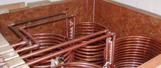
Not a single heating boiler system can operate without a copper heat exchanger. The operating principle is simple. Water begins to circulate through the coils in the pipes, heats up, flows into the system pipeline, into the radiators, from which it returns back, already cooled.
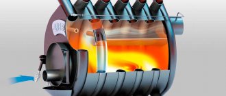
In private homes, a heat exchanger is installed to convert the stove into a water heating boiler. When making a homemade device, it is important to consider the size and shape so that the exchanger matches the dimensions of the stove chamber.
Radiators, a pipeline are connected to the exchanger, the pipes are heated evenly, and the heat is distributed throughout the house.
Comments: (9)
| Good to know 11/17/2016 | |
| What if it's made from copper? Will you have to clean it often? | |
| admin 20-11-2016 | |
| Made of copper? It is possible, but is it necessary? Clean the coil from the inside only chemically (citric acid?). I can’t tell you how often. | |
| sergey 29-11-2016 | |
| Stainless steel tubes for the coil need to be seamless or can be suture | |
| admin 29-11-2016 | |
| I had a seamless one. It seems to me that it is more important that it be made of food grade stainless steel, and whether it is seam or seamless does not matter. You're not going to shoot from it. | |
| Vladimir 01/17/2017 | |
| Were there any problems with sand spilling out of the tube? | |
| admin 01/19/2017 | |
| Absolutely no problem, take out the wooden plugs, lightly tap on the coil and the sand pours out. When everything is poured out, you can blow out the pipe and rinse it with tap water. | |
| Vladimir 03/12/2017 | |
| how can I order one from you? | |
| admin 15-03-2017 | |
| I'm sorry, but I can't help with this. The coil was made for a good friend and therefore the investment of time and effort was not critical. | |
| Alexander 23-12-2019 | |
| Very intelligible and quite realistic for repetition, thank you! I want to use it for pasteurization of wine. Is it (dry wine) also classified as “low concentration alcohol solutions”? | |
Advantages and disadvantages
The obvious advantages of the heat exchanger include:
- simplicity of its manufacture and installation;
- heating can be combined; in addition to heating, a water heating system can be installed;
- fuel for the device can be varied: solid, gas - liquid;
- The devices are beautiful in appearance; you can give the interior a national style.
The heat exchanger has two disadvantages:
- there is no automatic control over media heating;
- The efficiency is not too high.
Heat exchanger using tube sheet
Necessary materials, tools, drawings
For the heat exchanger it is worth choosing:
- Capacity 90 -110 liters.
- Anode.
- Copper tube up to 400 cm long for a thermal heater. If there is no copper pipe, you can use aluminum or plastic, as long as it bends well.
- Power regulator for regulating heat supply.
There is no need to make a coil from steel, the material is bad for heat transfer, it doesn’t matter how it bends, the air heats up thanks to copper many times faster. When using steel, you will additionally need a pipe bender.
Power calculation
It is very difficult to make an ideal heating system without knowing the power of the heat exchanger. When calculating this indicator, the following parameters should be taken into account:
- pipe diameter;
- length of the heating device;
- thermal conductivity of the metal used;
- maximum fuel combustion temperature;
- fluid circulation speed.
If it is problematic to establish these initial values, you can use an average calculation, based on the fact that to obtain a power of 1 kW, you will need a meter of pipe with a radius of at least 2.5 centimeters.
Types of maintenance
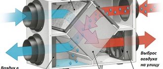
Diagram and operating principle of a recuperative heat exchanger
Based on the operating principle, the equipment is divided into recuperative and regenerative. In the first, moving coolants are separated by a wall. This is the most common type and can come in various shapes and designs. In the second case, hot and cold coolants alternately contact the same surface. High temperature heats the wall of the equipment during contact with a hot medium, then the temperature is transferred to the cold liquid upon contact with it.
According to their purpose, heat exchangers are divided into two types: cooling - they work with cold liquid or gas, while cooling the hot coolant; and heating ones - interact with the heated environment, giving energy to cold flows.
There are several types of heat exchangers by design.
Collapsible
They consist of a frame, two end chambers, separate plates separated by heat-resistant gaskets and mounting bolts. Such equipment is easy to clean and can increase efficiency by adding plates. But collapsible maintenance units are sensitive to water quality. To extend their service life, additional filters must be installed, which increases the cost of the project.
Lamellar
A plate heat exchanger requires the installation of additional filters on the coolant.
They differ in the method of connecting the internal plates:
- In brazed TOs, corrugated stainless steel plates 0.5 mm thick are made by cold stamping. A gasket made of special heat-resistant rubber is installed between them.
- In welded plates, plates are welded together to form cassettes, which are then arranged inside steel plates.
- In semi-welded maintenance, cassettes are fastened together using paronite joints in a structure consisting of a small number of welded modules. These modules are sealed with rubber gaskets and connected by laser welding. Then they are assembled between two plates using bolts.
Plate heat exchangers are used in high pressure and extreme temperature environments. Such devices require minimal maintenance, are economical and are highly efficient. In addition, the efficiency of the equipment can be increased or decreased as needed by increasing or decreasing the number of steel plates.
The only drawback of a corrugated stainless steel heat exchanger is its sensitivity to the quality of the coolant; it requires the installation of additional filters.
Shell and tube
They consist of a cylindrical body in which bundles of tubes arranged in grids are placed. The ends of the pipes are secured by flaring, welding or soldering. The advantage of such equipment is that it is undemanding to the quality of the coolant and can be used in technical processes where aggressive environments and high pressure are present (in the oil, gas, chemical industries). The disadvantages of shell-and-tube maintenance are relatively low heat transfer, large dimensions, high cost and difficulty in repair.
Seals.
If the fitting has a threaded part with a nut, thanks to which it can be secured in the casing body through rubber seals, then the tube of the stainless coil must somehow be passed through the plastic of the casing, and in such a way that water does not leak. For these purposes, I had to make a cunning homemade rubber seal (2 pieces) (see picture) with a groove for plastic.
Using a sharpened large-diameter tube, I cut out two cylindrical seals from thick sheet rubber (thickness about 14mm). Then, using a smaller tube (d < 10mm), central holes were made in each seal (a dashed line passes through them in the figure). Then the seals were mounted on a suitable bolt, the bolt was clamped into a drill and, using a piece of a square needle file, grooves for the plastic were machined (turned, loudly said, rather rubbed) on the rubber seals:
Important! The hole in the plastic of the plumbing pipe covers was drilled in such a way that the rubber seal was inserted into the plastic very tightly. Thus, after insertion, the central hole (which was already made with a diameter of slightly less than 10 mm) was additionally crimped. When inserting the coil tube, the rubber is sandwiched between the coil tube and the plastic hole, thereby sealing the joint. No additional sealants (silicone, etc.) were used.
Do it yourself
Before starting to manufacture a heat exchanger, it is necessary to decide what principle of heat transfer will be implemented in such a device.
Manufacturing of plate heat exchanger
To make such a device, you need to prepare the following materials and tools:
- welding machine;
- Bulgarian;
- 2 sheets of stainless corrugated steel 4 mm thick;
- flat sheet of stainless steel 4 mm thick;
- electrodes;
Build process:
- from stainless, corrugated steel , in the amount of 31 pieces.
- Then , a tape with a width of 10 mm and a total length of 18 meters is cut from a flat stainless steel. This tape is cut into pieces 300 mm long.
- The corrugated squares are welded to each other , with a 10 mm strip on two opposite sides, so that each subsequent section is perpendicular to the previous one.
- As a result , you get 15 sections facing one way and 15 facing the other in one cubic body. The corrugated surface of such sections allows you to effectively transfer heat from one coolant to another, while there is no mutual movement of different or homogeneous media.
- In the case when not an air mass, but a liquid is used to transfer heat, a stainless steel manifold is welded to those sections in which water will circulate. The collector is made of flat stainless steel. For this purpose, rectangles are cut out with a grinder: 300 * 300 mm – 2 pcs; 300 *30 mm – 8 pcs. Thus, you get a kit from which 2 collectors are welded, which resemble in shape a square box lid.
- A hole is made in each of the collectors , to which a pipe is welded for subsequent connection to the pipes of the heating system or to provide hot water supply.
- Holes on the collectors are made at one of the corners a, and when installing them on a heat exchanger, the inlet pipe should be located in the lower part of such a structure, and the outlet pipe in the upper part.
The heat exchanger discussed above is installed with the open side into the hot gas circulation system.
Thus, the hot gaseous coolant will transfer heat to the corrugated walls of the stainless steel plates, which, in turn, will heat the liquid.
A heat exchanger of this design can be used to transfer heat from one liquid to another. To do this, a steel jacket with a pipe of the above-described design is welded onto the open parts of the plates on both sides.
Drawing:
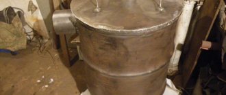
Manufacturing a water heat exchanger for a furnace
A conventional wood stove can not only heat a room in the traditional way, but can also be used to heat water for heating rooms in which this heating device is not installed.
To make such a device you will need the following materials and tools:
- steel pipe with a diameter of 325 mm, a length of 1 meter;
- steel pipe with a diameter of 57 mm, a length of 6 meters;
- steel sheet 4 mm thick;
- welding machine;
- electrodes;
- cutting torch;
- white marker;
Manufacturing process:
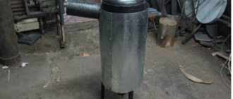
- A cylinder made of a pipe with a diameter of 325 mm is installed vertically on a steel sheet and outlined with a marker or chalk.
- The outlined circle is cut out with a gas cutter. Then, using the resulting metal pancake, another circle of the same diameter is made.
- In each of these pancakes, 5 holes with a diameter of 57 mm are cut. Such holes should be equidistant from each other, as well as from the middle of the pancake and its edge. The pancakes are welded to the cylinder so that their holes are located opposite each other.
- A 57 mm pipe is cut with a grinder into sections 101 cm long. It is necessary to prepare 5 such sections.
- Each piece of pipe is installed in the holes so that the edges of this pipe protrude 1 mm from the holes of the upper and lower “pancakes”. Pipe sections are welded using electric welding. The result is a metal cylinder, inside of which there are pipes of smaller diameter. Hot air and flue gases will pass through these pipes, as a result of which the pipe will heat up and transfer heat through its walls to the liquid that will be located inside the cylinder.
- To circulate liquid inside the metal cylinder, pipes are welded in its lower and upper parts. Cold water will be supplied from the bottom of this design, and the liquid heated in this way will be taken from the top.
Design features
Most often, a metal tank with a capacity of up to 5 liters with built-in pipes acts as a heat exchanger. There is no direct contact with fire. The device allows you to heat cold water, which then flows into radiators or a removable tank of larger capacity located in the same or an adjacent room.
As a result, by heating the stove in one room, it will be possible to heat another. According to its design, the heat exchanger for a furnace can be external or internal.
External
This type is very similar to a tank filled with coolant. Inside the container there is a part of the pipe used to remove combustion products. In terms of its design, the external heat exchanger is more complex than the internal one, as it places increased demands on welding work.
However, its maintenance is much easier. If necessary, the tank can be dismantled to remove scale or eliminate leaks.
Interior
Mounted above the firebox directly inside the stove. It is easy to install, but if maintenance is necessary, certain difficulties may arise. Especially if the stove is made of brick.
To avoid this, at the time of design development it is worth taking care of the maintainability of the future heat exchanger.
How to make a booster for flushing a heat exchanger
The booster consists of a reservoir, a pump for water circulation and an electric heating element. There is no need to disassemble the heating boiler for flushing, just disconnect the pipes, connect a hose to one of them and pump a chemical solution through it into the unit. The solution will pour out through the other pipe, but you also need to connect a hose to it.
Of the chemical reagents, hydrochloric and sulfuric acid are mainly used; phosphoric and nitric acid can also be used.
Cleaning the heat exchanger is not difficult, but it is necessary to follow safety precautions, that is, first disconnect the device from the power source, be it gas, water, or electricity. Dismantling must be done carefully; a damaged seal can lead to leakage of the structure, and the equipment will quickly fail.
Tips and tricks
- It is important to design a heat exchanger correctly , calculate economic efficiency, the percentage of hydraulics, indicate heat losses, calculate the design according to the geometric parameters of the unit and its components, and calculate the thermal insulation of the device.
- simpler design for making it yourself
- You can connect the heat exchanger to the system using fittings , place one at the bottom for cold water inlet, the second at the top for hot water inlet.
- When installing the exchanger, install the pipes at a slope according to the diagram.
- When installing the unit to a furnace and using coal for combustion as a material for the exchanger, it is better to choose cast iron; it is durable and fireproof.
- To make an exchanger with your own hands, take any model as an example and follow its parameters.
- When using the stove for heating and water supply purposes, the exchanger should absorb no more than a tenth of the heat generated.
- Pellets are good fuel and cheap in price, they do not emit soot, which is very important for cleanliness.
- Check the seams at the exchanger , you must not allow them to leak; under pressure or high temperatures, the entire structure can become unusable.
- Make the calculations correctly , otherwise your work will cost you dearly.
- A heat exchanger of the pipe-in-pipe type is easy to clean , lasts a long time, is simple to manufacture, and can operate under pressure. It is considered the most acceptable option for making it yourself.
As you can see, making a heat exchanger yourself is not difficult. For a simple design, a tank, two copper tubes of different diameters, a coil and a fan are enough. Thanks to the device, you can not only heat the room, but also cool it.
A thing like an exchanger in one form or another is found in almost every home. Approach the work constructively and thoroughly, prepare drawings, decide on the choice of material, follow the instructions described above for the manufacture, assembly and connection of the device.
If you wish and follow consistent steps, you will assemble a design no worse than a store-bought one, the house will be warm and cozy, and the device will work flawlessly for a long time.
Choosing the design of the device
When choosing a suitable heat exchanger for a furnace, you should strive to ensure that the total surface area of the finished product is as large as possible. This will ensure the most efficient heating of the room.
Coil
The most widespread are registers (coils). Such heat exchangers are made from smooth-walled pipes with a diameter of 40 - 50 mm. Outwardly, they resemble a characteristic L-shaped grille. For their manufacture, you can use not only round, but also profile pipes with a similar cross-sectional area.
The return and hot water outlet can be located either on one side of the register or on different sides.
The output option is determined by the design features of the furnace itself and the piping layout of the heating system.
The next most popular are rectangular or cylindrical tanks, inside of which there is a pipe or coil. The length of such a heat exchanger depends on the parameters of the furnace firebox. The heat exchanger installed on the chimney usually has a cylindrical shape. There is a pipe running inside it, the diameter of which is equal to the diameter of the chimney. The pipes are welded from below. Can be used both for heating a room and for heating water.
This design requires special attention. Due to the rapid cooling of combustion products, the draft in the chimney itself is significantly reduced. This helps slow down fuel combustion.
Installing the product on a heating and cooking stove requires special attention. Care must be taken to ensure that hot gases pass over the top shelf and enter the chimney at the front of the firebox.
In this case, the cooking plate can be located directly above the heat exchanger. It is also possible to manufacture a register without a top shelf. The so-called shelf consists of lower and side parts connected to each other by pipes.
Specifications
Plates and gaskets can be made of various materials; their choice depends on the purpose of the unit, because the scope of application of such heat exchangers is very wide. We are considering heating and hot water systems, where they act as thermal power equipment. For this area, the plates are made of stainless steel and the gaskets are made of NBR or EPDM rubber. In the first case, a stainless steel heat exchanger can operate with water heated to a maximum temperature of 110 ºC, in the second - up to 170 ºC.
For reference. These heat exchangers are also used for various technological processes when acids, alkalis, oils and other media flow through them. Then the plates are made from titanium, nickel and various alloys, and the gaskets are made from fluorine rubber, asbestos and other materials.
Calculation and selection of a heat exchanger is carried out using specialized software according to the following parameters:
- required liquid heating temperature;
- initial coolant temperature;
- required flow rate of the heated medium;
- coolant consumption.
Note. The heating medium flowing through a plate heat exchanger for hot water supply can be water at a temperature of 95 or 115 ºС, or steam heated to 180 ºС. This depends on the type of boiler equipment. The number and size of the plates are selected in such a way as to obtain water at the outlet with a maximum temperature of no more than 70 ºС.
It must be said that the advantages of plate heat exchangers lie not only in their modest size and ability to provide high flow rates. The fact is that the range of selected exchange areas and costs for the units under consideration is extremely wide. The smallest of them have a surface area of less than 1 m2 and are designed to flow 0.2 m3 of liquid in 1 hour, and the largest - 2000 m2 with a flow rate of over 3600 m3/h. The table below presents the technical characteristics shown by the operation of plate heat exchangers of the famous ALFA LAVAL brand:
According to their design, heat exchange units are of the following types:
- collapsible: the most common option, allowing for quick and high-quality repair and maintenance of a high-speed heat exchanger;
- soldered or welded: such devices do not have rubber gaskets; the plates are rigidly connected to each other and placed in a solid body.
Note. It is brazed heat exchangers that many craftsmen use for private homes, adapting them for heating or cooling water.
Connection diagrams
In addition to the type of heat exchanger, you must also choose the method of connecting it. There are several standard schemes. In any case, two outputs are connected to heating, one to cold water supply, one to hot/heated water distribution.
Parallel (standard)
In the simplest case, a heat exchanger for hot water from heating is connected in parallel to the existing system. This scheme is the easiest to implement, but for sufficient heating it is necessary that the coolant moves actively. That is, it is necessary to have a circulation pump in the coolant supply. In systems with natural circulation, this type of installation is ineffective.
Heat exchanger for hot water from heating: parallel connection diagram
During installation, the coolant supply is always connected to the upper pipe, and the return pipe to the lower one. When connecting water, the situation is the opposite - cold water is connected to the lower pipe, and the hot comb is connected to the upper one.
Heat exchanger piping diagram for DHW from heating
The simplest piping scheme contains shut-off valves on all four pipes - for the possibility of shutdown, cleaning, and maintenance. A mud filter with a fine mesh is also installed at the heating inlet. Since the gaps in the heat exchanger are very small, the ingress of scale or other contaminants can cause blockage of the channels. It is advisable to install the same filter at the cold water inlet - the equipment will operate longer.
This scheme can be improved by recirculating hot water in the DHW comb (looped after the last point of analysis). With this construction, the heat of unused hot water is not lost, but is used: water from the hot water comb is mixed with cold water from the water supply. It is no longer completely cold that is supplied for heating, but warm. The heat exchanger for hot water from heating only brings it to the required temperature.
Connection with DHW recirculation circuit
When disassembling heated water, mainly water from the cold water supply pipe is used for heating. When there is no analysis, the pump “drives” warm water in a circle, the load on the heating boiler is very small.
The temperature is controlled using a sensor and a control valve installed on the return (you can also install it on the supply). The readings from the sensor (water temperature in the DHW outlet branch) are sent to the control device. Based on the results of comparison with the set data, the intensity of the coolant flow is adjusted, thereby regulating the heating intensity.
Two-stage
The schemes described above are good for everyone, except that for heating a large flow of coolant must pass. Otherwise, the water will not have time to warm up. The second drawback is that you have to “turn off” the coolant flow from the heating system. With high flow rates and insufficient power of the heating boiler, temperature drops may be noticeable in cold weather. For a more rational use of heat, we came up with a two-stage system for connecting heat exchangers.
One of the options for two-stage connection of heat exchangers
In this case, the primary heating comes from the heating return pipeline. Thus, energy resources are used more efficiently. The temperature is brought to normal by reheating, but from the coolant that is supplied. You can connect the heat exchanger for hot water from heating in parallel - as in the top diagram. The second option is presented on the bottom - into the gap in the supply pipe from the heating system.
Two-stage heating option
When using the second scheme, primary heating occurs from the return. The water heated in this heat exchanger is supplied to the second one installed in the supply. Here it is brought to the desired temperature and sent to the consumer.
There is also a two-stage heating scheme using heat from hot water recirculation. In this case, the heat of previously heated water is rationally used.
Primary heating is from hot water recirculation, final heating is from the heating system
When using any of these schemes, the load on the boiler is significantly reduced. The heat that was not previously used is utilized. Thus, these schemes help save on energy.
For normal operation of a heat exchanger connected according to any of the schemes, technological requirements must be observed during installation. It is imperative to observe the slope of the hot water pipes towards the disassembly points. If the route passes above the door, an air vent is installed at the highest point. In addition, with a long route, additional automatic or manual devices for air release (air vents) are required. Otherwise, there may be problems with water supply.
