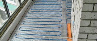
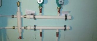
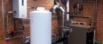
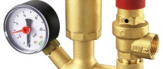
general information
Almost every heating system cannot be imagined without a heating distribution cabinet. Its installation solves several problems at once.
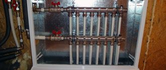
Compared to do-it-yourself pipe routing, manifold routing is much more efficient and practical, and even looks very aesthetically pleasing in a special cabinet. A manifold heating cabinet can accommodate both a meter and electrical equipment.
Here are a few points that prove that the distribution cabinet is an irreplaceable thing:
- in it you can hide the collector itself from view;
- there the connection of the heated floor system pipes with the entire heat supply system is carried out;
- this is a place for installing other connections and measuring instruments.
The manifold cabinet for heated floors is designed to hide and protect expensive engineering components from outside interference.
Manifold cabinet mounted
This is interesting: Methods of fastening sliding doors for a built-in wardrobe, facade decor
Additional equipment for the manifold
A good manifold assembly consists not only of a pipe and several valves; there is a certain set of equipment that will help make the operation of a heated floor pleasant and functional.
The mixing unit is designed to reduce the temperature of the coolant to operating temperature, by mixing return water with that from the boiler, as well as to circulate water in the heated floor circuits. Such a unit consists of a circulation pump and a three-way valve (a two-way valve can also be installed). It is also possible to install an expansion tank.
Operating principle of a mixing unit with a three-way valve:
The hot coolant enters a three-way valve on which a thermostat with a remote temperature sensor is installed, where it is mixed with cooled water from the heated floor circuits. Then the mixed water is pumped back into the heated floor system. A remote temperature sensor is installed after the pump and regulates the valve opening gap to maintain the set temperature. A check valve must be installed on the return circuit of the heated floor; it limits the flow of hot water to the return circuit outlet. It is also possible to install a bypass between the supply and return circuits; this is a pipe of smaller diameter, it serves in case all circuits are closed, then the pump will drive water through it. In the video you can study in more detail the principle of operation of the mixing unit; it also describes the principle of operation of the heated floor system.
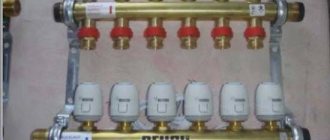
Thermostats are used to regulate room temperature. They are installed, if necessary, in each room and regulate the amount of opening and closing of the servos. There are both mechanical and electronic ones; for residential premises it is worth giving preference to electronic options, since their on-off error is much less than mechanical ones.
Thermostatic heads , installed on three-way valves, regulate the mixing of the coolant. For heated floors, heads with an external temperature sensor are used, made in the form of a glass tube or a can of gas, which is very sensitive to temperature changes.
When the gas is heated from the pipe on which it is installed, the gas expands, transfers pressure to the cartridge installed in the head and the gap is adjusted for the flow of coolant and, consequently, the temperature in the heated floor circuits.
In all heating systems, including underfloor heating systems, a safety group is used, which includes:
Temperature and pressure sensors (thermometer and pressure gauge) are necessary for visual monitoring of these parameters in the system. You can purchase a pre-assembled sensor.
An expansion tank is installed to compensate for the expansion of water when heated; if there is a tank at the heating boiler, there is no need to install a backup one at the collector.
An automatic air vent is necessary to bleed air from the system; it is installed on the inlet and outlet manifolds. at the highest points.
safety valve is needed to relieve emergency pressure, it is installed if the system has an expansion tank, it is mainly installed at the heating boiler, and the response threshold should be selected according to the heating boiler (indicated in the boiler passport).
Principles of drawing up wiring diagrams
There are no uniform planning standards when drawing up wiring diagrams for a collector system. Equipment is selected for specific tasks.
And one of the prerequisites for the implementation of the scheme is the need to connect all batteries to one riser.
You may also find useful information on how to connect a heating radiator.
To implement a collector wiring diagram in an apartment, you will have to leave only one heat channel, having previously welded the rest - it will take on the entire load
If you weld all the other water supply channels so that one riser takes on the entire load, a closed hydraulic circuit is formed within one apartment. All heating devices located higher up the riser will be cut off from the system and will not receive the desired heat.
Residents living above will sooner or later discover the reason for this phenomenon, and the scheme will have to be forcibly redone again, paying a considerable sum.
Manifold heating distribution can be installed in new apartment buildings, provided that additional valves were installed in them during the construction stage to connect circuits of various configurations.
When arranging a collector system, you should take into account a number of key points that are also typical for other types of systems
The collector system is ideally suited for private homes.
The main thing is to adhere to the basic recommendations of professionals when designing the wiring:
- Availability of an air vent. The automated valve is placed directly on the supply and return manifolds.
- Availability of expansion tank. Its volume indicator must be at least 3% relative to the total volume of coolant. But it is also possible to use devices with a larger volume.
- Location of the expansion tank. It is installed on the “return”, placing it in front of the circulation pump along the flow of water. More details about its installation are described in our other article.
- Installation of circulation pumps on each circuit. Their location is unimportant, but due to the low operating temperature they exhibit maximum efficiency on the return line.
If it is necessary to use a comb equipped with a hydraulic compensator, an expansion tank is installed in front of the main pump, which is designed to ensure the movement of water in a small circuit.
By placing an expansion tank in front of the pump, the risk of damage to the device due to water turbulence can be significantly reduced.
The circulation pump is fixed so that the shaft is strictly horizontal. Otherwise, the very first air lock will leave the unit without lubrication and cooling.
If there are additional distribution nodes in the heating system, they should not be communicating.
System elements
After connecting the cabinet, install the supply and return pipes. Hot water moves through the supply circuit from the boiler. The liquid cooled during heating flows back to the heating source.
The circulation of the coolant occurs due to the pump. A shut-off valve is installed in the cabinet on each pipeline. If it is necessary to remove several elements from the system (during repair work or if you want to save money), this does not affect the heating in other parts of the house. You just need to turn off two taps.
Compression fittings will help if it is necessary to connect a plastic pipeline and a metal valve.
The main components of the cabinet:
- The case is a box that consists of stainless steel or durable plastic.
- Fastening system (depending on the location of the structure, on the surface or in the middle of the wall).
- Often spacers or anchors are used as fastenings. Some cabinets have brackets and adjustable clamps.
- The door is its function in protecting the contents from unnecessary external interference. It is attached with hinges and has a lock or latch. Popular design colors are white, beige, and less commonly, other shades.
It is not difficult to make a manifold cabinet with your own hands. However, it is not so expensive in specialized stores to waste time on its creation.
More information about the manifold for heated floors can be found here.
Specifications
Powder-coated steel cabinet
The bodies of built-in boxes are made of high quality heat-resistant plastic or 1 mm thick steel sheets. Protection against corrosion is provided by coating the housing with special powder or polymer agents. The standard color is white, beige or gray.
The basis for the manufacture of wall models is metal that has not been galvanized. The product is completely painted. The holes for the pipe outlets are covered with metal plates. Boxes of this type are distinguished by free access to the distribution unit. The models are equipped with a heating regulator, which allows monitoring the operation of the devices. The dimensions of the products in this series are identical to the dimensions of the built-in types.
When choosing a manifold cabinet for a heated floor, it is important that the number of outlets corresponds to the actual layout. The output and supply lines of the heating system are also taken into account. The box should accommodate the main and additional devices. The type and direction of door opening plays an important role. Removable elements are installed on the left or right, depending on consumer needs.
Dimensions
Built-in and wall-mounted cabinets have the same dimensions. The depth of the devices is 12 cm, the height is 65 cm, and the width is from 46.5 cm to 19 cm. The height is adjustable with legs that can raise the product by 10 cm.
What are collector systems for underfloor heating?
A water heated floor system consists of many circuits - pipes through which the coolant flows. Its temperature rarely exceeds 35–40 degrees Celsius. Technically, only condensing gas boilers are capable of operating in this mode. But such boilers are rarely used for collector heated floors.
A standard boiler heats the coolant to 70–90 degrees Celsius. Such a high temperature is not suitable for heated floors. To ensure that coolant of a suitable temperature enters this system, a collector is used. The principle of its operation is simple: in the collector, two water flows are mixed - cooled return and hot from the feed coming from the boiler. As a result, the required coolant temperature level is achieved.
To create the same temperature for all underfloor heating circuits, the coolant first flows to the manifold comb. The main part of the cooled water is pumped into the heating boiler, but a certain volume of return water is supplied to the mixing system and serves to cool the coolant heated in the boiler. In fact, these devices (return and supply combs) are called a heated floor collector. Combs are not always equipped with a mixing unit.
The ideal collector floor system consists of circuits of equal length, and water of the same degree of heating enters the collector. This achieves a certain balance and equilibrium of coolant temperature in the system. But this wiring option is practically never found, because the rooms in apartments and houses are different in geometry and area, and therefore the length of the pipeline in the heated floor system will not be the same. Accordingly, heat loss increases over longer sections and the return temperature will be lower.
The temperature difference between the flows is compensated by installing flow meters on the supply comb, and special valves on the return comb, allowing adjustment of the coolant flow rate. Flow meters are a device that informs about the speed of water movement in a pipeline. A special float is installed in a transparent plastic case, which allows you to determine the flow rate of the coolant using a graduated scale.
The principle of temperature control is simple: the higher the flow rate, the more heat the circuit through which the liquid moves can give off. And vice versa, if you want the temperature of the collector heated floor to be lower, close the control valve, thereby reducing the flow rate and heat transfer of the floor.
The flow rate is changed by turning the valve handle; each circuit can be configured individually. When installing a manifold heated floor, it is best to sign the adjustment valves and circuits and also put them on the diagram so that in the future you do not have to look for a match between the valve and the circuit.
Manual adjustment is not always convenient. Today, collector floor heating systems use automatic devices. Special servos are installed on the valves, which receive a command to close or open the flow from thermostats installed in each room. If the room temperature is lower than set, the thermostat sends a signal to open the valve more, and vice versa.
Functional purpose
Let's start with the fact that there is one very important rule, and if it is not strictly adhered to, the heating system at home will not work well. This rule states that the diameter of the outlet pipe of a heating boiler should always be equal to or slightly less than the total diameter of all circuits consuming coolant. The best option is if it is larger
The best option is if it is larger.
For comparison, here is an example of a wall-mounted unit in which the diameter of the outlet pipe is ¾ inch. Imagine that this boiler will heat three separate circuits:
- The main heating is a radiator system.
- Warm floor.
- An indirect heating boiler that will use water intended for household needs.
Now imagine that each loop is at least ¾ inch in diameter, just like the boiler. But the total figure will be three times greater. That is, no matter how much you want, it will be simply impossible to dispense the required amount of coolant through the diameter of the heating boiler pipe so that it is enough for all three circuits. So much for the reduction in heat transfer throughout the entire area of the house.
Of course, individually all circuits will work fine. For example, the main circuit (radiator) without turning on underfloor heating will completely overpower the heated space. But as soon as you turn on the underfloor heating system, there won’t be enough coolant either here or there. The coolant has enough temperature, but its volume is not enough.
This rather serious problem is solved by installing a distribution manifold in the heating system. In essence, this is a structure made of stainless metal pipes, in the structure of which devices are installed for the input and output of coolant distributed along the circuits. To regulate temperature, pressure, flow volume and its speed, shut-off valves are installed along the terminals, which perform all the necessary functions.
The most important thing is that with the help of a distribution manifold you can control the temperature in a separate room. And this will not affect the neighboring rooms or the temperature of the house as a whole.
Collector device
The collector consists of two pipes:
- Connects the supply pipeline from the boiler to the supply circuits of heating systems. This compartment helps distribute hot water. Its device is especially helpful when the question arises of repairing a particular outlet. In this case, on a certain circuit where repair work needs to be carried out, the shut-off valve is closed. It simply shuts off the coolant supply.
- The return compartment regulates the pressure inside each circuit, which ensures the quality of coolant movement. And, therefore, the quality of heat transfer from heating systems.
Anyone who does not understand the essence of installing a distribution manifold begins to build various additional installations into the heating system: a circulation pump, valves for various purposes, and so on. Let's face it, this will not help; they cannot be used to increase the volume of coolant. You will simply make unnecessary expenses that will be in vain.
Attention! If you own a large multi-storey building, it is recommended to install a separate distribution manifold on each floor
Advantages of a distribution cabinet
A manifold heating cabinet is a practical and necessary thing for the following reasons:
- Its use makes it possible to reduce the number of pipes required to connect a heated floor. The pipes do not require pulling from the heater, since the collector can be placed in the same room.
- In addition to manifold installation, the cabinet can also be used for water supply; a liquid metering device is installed in it.
- When repairing and upgrading the heating system, you can easily gain access to the guide circuit.
- Safety is one of the most important points. A door with a key will help protect the manifold cabinet with expensive components from children.
This is interesting: Tips for choosing a three-door wardrobe, placement features
Types of manifold cabinets
Built-in manifold cabinets
Depending on the design features, manifold cabinets for heating are divided into two types: built-in and external. The side segments of the products are adjustable in depth, which makes it possible to install them in walls with different thicknesses. On both sides of the box there are service entrances for pipes of different sections, which simplifies installation.
Built-in
The built-in cabinet for a heated floor manifold is represented by a segment of models installed in niches under plasterboard sheathing, as well as inside building structures.
The cabinets are equipped with removable lids. There are slots in the sidewalls intended for the exit of pipes and fastening elements. The boxes are equipped with retractable legs.
External
External manifold cabinet
The need to install an external box arises if the thickness of the partition or wall at the installation site is less than its size. The restriction on the arrangement of niches is explained by the risk of breaking the structure of the load-bearing wall, which entails a weakening of the multi-story building as a whole. Sometimes sampling a niche is impossible due to the high hardness of the material. In this case, external models are indispensable. Their price is higher, since they require finishing of the side walls and the use of additional elements during installation and fastening.
External manifold cabinets can be wall-mounted or floor-mounted, depending on the mounting method. Wall boxes feature simplified installation. Removal of the outer cladding is not required. There are also legs. The product has an aesthetic appearance and remains invisible after installation.
Floor-standing models are used when it is necessary to heat a large room.
Installation and location
The structure is installed on a solid wall, taking into account the level of floor elevation.
When attaching a built-in type of cabinet, a niche is required. If the recess was made during the construction of the room, there will be no difficulties during installation.
The following installation steps are distinguished:
- marking the wall for a collection of pipes is planned;
- using a wall chaser, holes are made in the wall for the cabinet;
- the box is connected on the sides in the wall niche using anchors;
- the contours are fastened;
- after installing the heating distribution unit, the circuit is closed and checked for leaks;
- the gap between the wall and the cabinet is covered with mortar and then puttied.
Installation of wall-mounted models is easier:
- places for fastening are marked on the walls;
- holes for anchors are drilled using a hammer drill;
- the box is fixed with screws;
- the cabinet is aligned according to the marked marks;
- a collector is installed;
- the circuit is connected;
- A trial run of the system is performed.
Installation of cabinets for heating manifolds is carried out quickly. When attaching the device, the recesses in the wall do not become an obstacle. A detailed drawing, drawn up taking into account the size of the box, its technical features, as well as the communication points, helps during installation.
Optimal performance is achieved when installing the product in the middle of a heated room near the floor surface. Particular attention is paid to the evenness of the working base. The structures that hold the device must not be level.
The cabinet for the heating system manifold is connected taking into account the raised floor level. After installing the box, the supply (input) and return (return) pipes are inserted into it. The inlet pipe supplies hot water to the circuit. The return pipe drains the cooled liquid into the boiler for subsequent heating. The location for the distribution cabinet is selected in such a way that the heating system circuits have the same length, but not more than 70 meters.
When choosing the optimal location, it is recommended to seek professional help. Installation errors can result in excessive pipe consumption or deviations in the pressure readings of the heating system.
Tips for box location
In the room, a place is selected to install the cabinet, and for collections of floor pipes, they should have approximately the same length - 70 cm. The collector is hidden in a cabinet that has a metal box (or made of strong plastic), it is attached to the wall in a recess. In the middle there are vertical bars that align with the width of the main device. It is used to connect circuits and other elements of the room’s heat supply, and install additional equipment.
The cabinet for the heated floor manifold is connected taking into account the increase in the floor to the point of the thickness of its layers.
Having secured it, introductory hot water and return water are carried out. The supply pipe serves to supply hot media from the general central heating system. The return water is responsible for removing cooled water in the heating device, where it is heated again.
Device
When installing a water heated floor, the work may take little time. Everything will depend on the length of the heated floor, the availability of appropriate equipment and materials, as well as skills.
A manifold with a pump for a heated floor is one of the components of the entire system to ensure the supply of heat to the room. At the same time, it has a unique character of performance with its own nuances. The most basic of them is that the preparation of pipelines is carried out separately from the entire system. And this despite the fact that the coolant circulates through all pipes at the same time.
The manifold is necessary in order to be able to isolate the supply and return pipes from the water heating installation. The kit necessarily contains the following components:
- Pump group.
- Heating fluid distributor.
- Return cooled water collector.
Nobody thinks about how much it costs to install heated floors. It is best to purchase components together and from one manufacturer. This is the only way to achieve the highest quality. In addition, in this case the cost will be lower, regardless of the length of the heated floor circuit.
functions, design, types, dimensions of the box for the heating manifold
A manifold cabinet is special equipment that simplifies the heating and water supply of a home.
The modern approach to a single manifold cabinet makes it easier to organize the heating structure of a living space.
Odnoklassniki
Functions of the manifold cabinet
The manifold cabinet is a place where heating equipment and water supply are combined. Its only function is to hide various pipes, faucets, button valves, and so on.
The cabinet itself is a place in which the equipment responsible for supplying water to the house and heating it is placed.
In addition to pipes, pumps are also connected to the cabinet, regulating, for example, heated floors. The collector is often installed so that the temperature and floors can be regulated differently in each room, making, for example, “savannah” in one, and “Antarctica” in another.
Reference. The price and temperature differences between collectors differ depending on the supplier company and the material of manufacture.
Advantages of installing collector equipment:
- One of the most important advantages of the collector device is its simplicity of construction. Installing a locker from a handyman does not require in-depth knowledge or qualifications to understand the intricacies of electrical, mechanical or technical craftsmanship. Anyone can install collector equipment, which reduces its price in the eyes of other complex mechanisms of heating equipment and water supply.
- Many technologies that make up a complete set of manifold cabinet allow you to transfer water and heat it as quickly as possible. For example, a circulation pump through pipes with maximum efficiency is capable of delivering heat to heating radiators. Because of this, the heating or cooling time is increased.
- The advantages of collector equipment with maximum efficiency include minimal fuel consumption for heating. This helps the locker owner save on purchasing liquids.
ogon.guru
Purpose and main elements
A manifold cabinet for a heated floor will hide the manifold from prying eyes. Here the connection of heating pipes and other heat supply elements is made. In addition, there are adjustment devices there.
Having connected the cabinet, install the supply and return pipes. The supply pipe provides hot coolant coming directly from the boiler. And the return one accumulates water that gave off heat during heating. She returns back to the boiler and heating begins again.
Regular movement of water is supplied by a dedicated pump. In the installed cabinet, a shut-off valve is fitted to each pipeline. When a situation arises that it is necessary to remove several elements from the system (due to repairs or due to savings), heating does not affect the remaining parts of the house. Only one thing needs to be done - turn off both taps.
The joining of a plastic pipeline and a steel valve is carried out using a special compression part - a fitting.
Manifold cabinets are metal devices in the middle of which the floor and water supply mechanism is located. The main purpose of the collector is to independently control the circulation of the coolant, and is also able to provide the floor with the required temperature.
The main parts of the cabinet are:
- body – a box consisting of stainless metal or strong plastic; there are models with the absence of a back wall or one of its sides; on the sides of the structure and its bottom panel there are slots for connecting pipes;
- fastening mechanism - the system is determined by how the structure will be located - on the surface or in the center of the wall; spacers or anchors are often used for fastening; in certain structures, brackets and adjustable clamps are fixed inside;
- door – protects the spacious cabinet from violations and prohibited entry; secured with hinges, equipped with a lock or latch; Many models can be purchased in white or beige, but if desired, it is possible to find other colors.
This structure can be made with your own hands. But, the cost of many devices is not too high, so it’s better not to bother and buy it in a store.
Varieties
There are 2 types of manifold cabinets:
- built-in devices - placed in a niche made in the thickness of the wall or hidden under a lining of plasterboard or lining. Typically, the sides of these models are not painted, since they contain outlet and fastening spans. Typically, the depth of the device is 120 mm, the width is 465-1900 mm, and the height is almost 650 mm. To simplify the designation on the niche and to accommodate different sizes of manifolds in the cabinet, certain built-in devices are equipped with retractable legs. Using this option, it is possible to raise the height of the structure to 100 mm;
- external manifold cabinet - these models are the easiest to install, as they are mounted on the wall surface. On the sides, the structure is coated with a special corrosion-resistant agent or powder paint. The outlet slots are initially covered with easily removable metal plates. The external wall-mounted manifold cabinet has dimensions almost identical to the parameters of the built-in structures. It is also possible to adjust the height using extension legs.
Built-in wardrobes are in greatest demand, because they are unnoticeable, do not overshadow the appearance of the room, and are easy to use. The cabinets are painted white; for the built-in ones, only the front panel is decorated. Strong locks are placed on the doors to prevent unauthorized entry into the system.
Built-in
Outer
Components of collectors
The design of a heated floor system using a manifold includes the following main components, which cannot be avoided:
- Floor supply manifold. It can otherwise be called a flow control valve for a single branch.
- Mixing unit, as well as a three-way valve.
- Adjustment valve with servo drive. This is the so-called return collector, which is almost identical in cost to the feeder.
- A circulation pump with a drainage device.
- System automation group.
- Combs, but if necessary. They are more suitable for supplying heat to the room using radiators.
Automatic control valves allow you to interrupt the supply of coolant to the heated floor after reaching a certain temperature. It no longer enters the circuit until it cools down. Here it no longer matters how much the heated floor consumes, since all indicators will decrease due to constant monitoring. Flow meters are also used to set the required parameters of the heat released into the room. Setting up is very easy and without unnecessary difficulties. They are located on the reverse side of the comb.
Both combs are connected to each other using a circulation pump. It allows water to constantly circulate throughout the underfloor heating system. It is worth noting that each of the elements of the collector group is purchased both separately and in aggregate. In the latter case, you don’t have to worry about something being missing or missing. But independently assembling the entire system requires certain knowledge. For example, it is worth knowing that you will have to purchase a drainage valve for the pumping group. In addition, before starting all work, it will be necessary to install the cabinet itself for the manifold, which is additionally equipped with an air exhaust point from the system.
The comb system is equipped with various measuring and indicating devices. This includes pressure gauges, thermometers, heating sensors, etc. The latter, by the way, are installed in the floor screed. Which floor filling option to choose should be guided by the requirements of the underfloor heating system itself and its features.
The quality of the design of the collector group for the heated floor will subsequently affect the performance of the heating system. In addition, the reliability of a water heated floor is based on all its components. Careful attention during installation will allow you to get the desired result that can last for a long time.
Rules for selecting components
Having completed all the calculations, the next step is to select the required set of mechanisms. The simplest set consists of shut-off valves. However, with such a device it is difficult to regulate the power of individual heating lines.
To solve this problem, crane axle boxes are installed on the feed comb, through which smooth adjustment is possible. Rotameters are mounted on the return manifold.
The collector parameters must be sufficient for convenient access to shut-off and control valves. The average range between the contours is 100-150 mm, the center distance between the feed and return combs is 250-300 mm
For warm water floors, the configuration scheme will be different. For assembly you will need the following elements:
- Shut-off and control valve. Installation is carried out on connecting pipes. With the help of this fittings, the flow of coolant is completely or partially stopped. It is recommended to use automatic modification.
- Rotameters. Such elements are mounted on the return collector. They perform a similar function as the previous element, only in the return pipeline.
- Mixing unit. By mixing hot and cold water flows, the specified heating operating mode is optimized.
The manifold kit is necessarily equipped with a safety group headed by a pressure gauge, air valve, thermostat and circulation pump. It can be supplemented with servo drives, the control of which is reproduced through the control electrical unit. Thus, the operation of the system can be automated.
Advantages
The manifold heating cabinet has the following features:
- the use of a distribution overhead structure can significantly reduce the number of pipes required to connect a heated floor; they do not need to be pulled from the heater, because the collector can be placed in the same room;
- In addition to installing a collector, this cabinet can also serve for water supply; it houses a water metering device;
- the cabinet mechanism provides the most convenient access to the guide system for repairs and modernization;
- and most importantly - safety, a turnkey door will be able to protect the building from children, and they, in turn, will not get burned.
In addition, a neatly painted door looks much more beautiful than a bunch of pipes and valves installed on the wall.
Design of different types of combs
A budget distribution comb with valves has one significant drawback - water can drip from under the handle.
Leakage occurs due to wear of the rubber seals. Threads at the ends are needed to connect shut-off valves and central hot water supply/discharge. In general, such a comb will cope with its function, but its flawless service life will not be very long.
If disassembling the valves and replacing worn seals does not lead to initial tightness, you will have to buy a new manifold.
A more complex design would be a comb with plugs on the return manifold (and on the direct one too). Instead of them, flow meters and thermal heads can be installed in the future. The direct and reverse combs in such models are already connected by a bracket for mounting on the wall.
The presence of plugs makes it possible, if necessary, to improve the heating distribution manifold. To avoid problems with the installation of thermostats and other components in the future, it is necessary to provide convenient access to the comb at the stage of its installation
And finally, a complex and expensive, but the most effective distribution comb with factory-installed flow meters and thermal heads.
Flow meters regulate the uniform delivery of coolant to its destination, and thermal heads can adjust the temperature for each outlet separately, just like for a heating radiator. The types of thermal heads, their operating principles and installation features are discussed in more detail in our other article.
Flow meter caps allow you to visually monitor coolant flow through the circuits. Thermal heads regulate the flow of coolant into each of them
Even during the design process, it is necessary to make a choice between different types of combs, but in any case, the collector system is a preferable choice compared to conventional wiring based on such criteria as ease of use and durability.
Features and Benefits
The manifold cabinet is a closed metal structure with a removable or fixed door, used to house the connection unit for heating pipes (including supply and return lines), control devices, shut-off and control valves. Such devices have an attractive appearance and successfully hide and protect all internal contents. In addition to heating equipment, the product can contain meters that monitor water supply or the operation of other plumbing or electrical appliances.
Manifold cabinets are mounted in close proximity to the floor. They are installed strictly vertically. It is not recommended to raise the distribution unit higher than 70 cm from the floor covering; the closer it is to the level of the pipes in the screed, the more efficiently the system will work. As a rule, the structure is placed in the room closest to the heating boiler, in an inconspicuous area. If there is no separate room or there is a need to hide several collector units inside, the cabinet is installed in the middle of the room. During installation, the level of raising the floor level after completion of all heating and finishing work is taken into account.
Regardless of the location of the cabinet, access to the door with internal filling remains free.
In the standard version, the manifold cabinet consists of:
- durable plastic or metal frame with slots for supplying communications;
- fastening systems for securely fixing the body inside a niche or on a wall;
- doors with an internal lock or latch to protect the system from children or unauthorized access.
How to choose the right tool cabinet, tips
The advantages of using collector structures compared to open wiring are obvious: all the necessary devices are placed at one point without damaging the interior, protected from external influences, and available for inspection or repair. Water heating with this scheme remains safe and functions as usual. Installing the distributor at the desired point can significantly reduce the consumption of water floor pipes.
What are the sizes of boxes and popular options?
As a rule, designs from the brands Grotto (Russia), Valtek (Italy), and Vester (Russia) are most often purchased. The cabinet sizes are different (see tables).
Dimensions of built-in manifold cabinets.
| Designation | Dimensions | Manufacturer |
| ShV-1 | 670×125×494 | Grota |
| ShV-1 | 648-711×120-180×450 | Wester |
| ShV-2 | 670×124×594 | Grota |
| ShV-2 | 648-711×120-180×550 | Wester |
| ShV-3 | 670×125×744 | Grota |
| ShV-3 | 648-711×120-180×700 | Wester |
| ShV-4 | 670×125×894 | Grota |
| ShV-4 | 648-711×120-180×850 | Wester |
| ShV-5 | 670×125×1044 | Grota |
| ShV-5 | 648-711×120-180×1000 | Wester |
| ShV-6 | 670×125×1194 | Grota |
| ShV-6 | 648-711×120-180×1150 | Wester |
| ShV-7 | 670×125×1344 | Grota |
Dimensions of external manifold cabinets.
| Designation | Dimensions | Manufacturer |
| SHN-1 | 651-691×120×454 | Grota |
| SHN-1 | 652-715×118×450 | Wester |
| SHN-2 | 651-691×120×554 | Grota |
| SHN-2 | 652-715×118×550 | Wester |
| SHN-3 | 651-691×120×704 | Grota |
| SHN-3 | 652-715×118×697 | Wester |
| SHN-4 | 651-691×120×854 | Grota |
| SHN-4 | 652-715×118×848 | Wester |
| SHN-5 | 651-691×120×1004 | Grota |
| SHN-5 | 652-715×118×998 | Wester |
| SHN-6 | 651-691×120×1154 | Grota |
| SHN-6 | 652-715×118×1147 | Wester |
| SHN-7 | 651-691×120×1304 | Grota |
| Shn-7 | 652-715×118×1300 | Wester |
After the system is installed and the branches are adjusted, it is necessary to perform a starting start, heating the heating structure in order to identify problems at an early stage. In addition, experts advise specially creating a working pressure in the system that is approximately 25% higher than during normal use, and paying attention to the tightness of the connections.
Russian companies producing collector equipment
- "GROTA"
The most popular company for its products, which has been in demand on the market for 20 years . Its high ratings indicate high-quality and long-term operation of the equipment from the owners.
Photo 4. Manifold cabinet from the manufacturer Grota. The product is locked with a key.
Some of the best built-in manifold cabinets can be found at. Keeping up with its direct competitors GROTA, the company quickly gained momentum. It has been on the technical market for more than 15 years , brilliantly selling heaps of built-in collector equipment that also serve their owners for a long time.
How does a manifold unit for a heated floor with a pump work?
The collector unit is a system in which the cooled coolant is mixed with the liquid heated in the boiler, the temperature is equalized to a suitable level. The collector allows you to adjust the temperature of the coolant circulating in the circuits of the heated floor system. The liquid heated in the boiler enters the collector, and from it into the pipes under the floor, where, having given up some of the heat, the water cools and returns back to the collector to be mixed with hotter water supplied from the boiler.
The process of mixing cooled and hot coolant is controlled using various sensors, valves, and control actuators.
To increase the efficiency of the collector heated floor, collectors with a pump are installed in the system, due to which the liquid circulates through the pipes forcibly.
The collector unit with pump has several basic elements that ensure its smooth and efficient operation:
- Circulation pump. This unit is installed on the coolant supply pipeline and promotes active pumping of liquid through the circuits. Using a pump allows you to increase the efficiency of the collector floor heating system several times.
- Mixing unit. A valve equipped with a servo drive that regulates the temperature of the coolant. Having received a command from the temperature sensors to open or close the valve, the servo drive increases or decreases the supply of hot liquid to the manifold, thereby achieving the desired coolant temperature.
- Distribution comb. A unit equipped with several outlets for the coolant, to which various circuits of the collector heated floor system are connected. A flow meter is installed on each circuit, which allows the liquid temperature to be adjusted using special valves - manually or using automatic servos.
- Air vent. This device is mainly equipped with expensive, ready-made systems of collector heated floors. An air vent is used to remove air trapped in the system.
- Weather sensor. A device that allows automatic adjustment of the collector floor system depending on weather conditions and temperature outside the window.
Modifications of distributor combs
Today, there are many types of collectors for heating systems on the equipment market.
Manufacturers offer both connecting links of the simplest design, the design of which does not provide for the presence of auxiliary fittings for regulating the equipment, and manifold blocks with a full set of built-in elements.
A collector block that includes all the necessary functional elements to create conditions for uninterrupted and high-performance operation of the heating system
The simple-to-use devices are brass models with one-inch branches, equipped with two connecting holes on the sides.
On the return collector, such devices have plugs, instead of which, in the case of “expanding” the system, additional devices can always be installed.
Intermediate assemblies that are more complex in design are equipped with ball valves. For each outlet they provide for the installation of shut-off control valves. Sophisticated, expensive models can be equipped with:
- flow meters, the main purpose of which is to regulate the flow of coolant in each loop;
- thermal sensors designed to monitor the temperature of each heating device;
- automatic air release valves for draining water;
- electronic valves and mixers aimed at maintaining the programmed temperature.
The number of circuits, depending on the connected consumers, can vary from 2 to 10 pieces.
Regardless of the complexity and versatility of the equipment, materials that are resistant to external factors are used in the manufacture of manifold block combs
If we take the manufacturing material as a basis, then intermediate prefabricated collectors are:
- Brass - characterized by high performance parameters at an affordable price.
- Stainless steel structures are extremely durable. They can withstand high pressure with ease.
- Polypropylene - models made of polymer materials, although they have a low price, are inferior in all characteristics to their metal “brothers”.
Models made of metal are treated with anti-corrosion compounds and covered with thermal insulation to extend their service life and improve performance parameters.
Separating structures made of polymers are used in the construction of systems heated by boilers with a power of 13 to 35 kW
Parts of the device can be cast or equipped with collet clamps, allowing connection to metal-plastic pipes.
But experts do not advise choosing combs with collet clamps, since they often “sin” by leaking coolant at the valve connection points. This occurs due to rapid failure of the seal. And it is not always possible to replace it.
Collectors are used in single- and two-pipe heating schemes. In single-pipe systems, one comb supplies the heated coolant and receives the cooled one
Installation nuances
When choosing the exact location of the manifold cabinet, you should consult with professionals. Errors at this stage are fraught with overuse of pipes or deviation of pressure indicators in the heating system from the optimal value. The best results are achieved when installing the cabinet in the middle point of the room, near the floor surface. Special requirements are put forward for the evenness of the working base. The structures holding the manifold cabinet must not be level.
The mounting pattern depends on the type of cabinet. Built-in models are installed after marking and laying grooves with mandatory fixation of anchors on the outer sides of the box. After installing the collector, the heating circuit is finally closed and its tightness is checked. If there are no leaks or pressure drops, possible gaps between the cabinet and the walls are covered with mortar or putty.
Features of the power distribution cabinet, main characteristics
Wall-mounted varieties are much easier to install. The anchor attachment points are marked on the walls, and the cabinet frame is fixed with screws. By analogy with built-in models, a trial start of heating becomes possible after installation is completed. Regardless of the chosen type of design, when placing the collector inside the cabinet, you should remember the need to ensure maximum tightness of connections and protection of control devices . A detailed installation diagram drawn up in advance, taking into account the dimensions, features of the cabinet and the location of communications, helps to avoid mistakes.
Prepare the mounting location according to the diagram
Install the cabinet, connect the heating system and check it, cover any gaps between the wall and the cabinet
Fastening technique
Each type of manifold cabinet has its own mounting nuances, which are worth remembering when installing them.
Built-in
If the deepening was made during construction, there will be no difficulties with installation. When planning a heated floor and installing a cabinet, carry out the following actions:
- selecting a location for the collector, which is assembled no lower than the floor height, since problems with heat supply are possible;
- mark the wall for pipe collections;
- using a wall chaser to make holes for a cabinet or pipeline;
- The structure is fixed into the wall niche and connected with anchors on the sides of the box;
- place the collector, fasten the circuits and heat supply;
- the gap between the cabinet and the wall is covered with mortar, then puttied.
Preparing the installation site
Installation
Outer
Installation is a little easier:
- select a location for the structure;
- place the box;
- aligned according to the drawn marks;
- drill holes for anchors with a hammer drill, screw the box together with screws;
- install the collector, connect the circuits;
- the wall remains the same - the cladding is not touched.
The cabinets are installed quickly. The recess does not delay the fastening process. After connection, there will be no problems with adjusting the system and water supply.
How are collector boxes attached?
Depending on the type of installation, distribution cabinets have two mounting options.
For built-in
Difficulties should not arise when the niche has already been provided for during construction work. When planning a heated floor system and installing a cabinet:
- Select locations for the collector; it should be assembled above floor level, since difficulties with heat supply are possible.
- Marking the wall for pipelines.
- Using a wall chaser, holes are made for the box and pipes.
- The distribution structure is inserted into the recess of the wall and connected with anchors to the sides of the cabinet.
- The collector is mounted, the circuits and heat supply are connected.
- The space between the cabinet and the wall ceiling is covered with mortar and putty.
For outdoor
Installation may seem easier to some:
- A location is selected.
- There is a closet.
- Aligned to drawing marks.
- Using a hammer drill, holes are made for the anchors, and the cabinet is screwed together with screws.
- The collector is installed and the circuits are connected.
- The wall remains the same, there is no need to touch the cladding.
Design sizes and popular manufacturers
The best producers are:
- the Russian company Grota produces devices at competitive prices from 1466-3454 rubles;
- the Italian company Valtec offers cabinets priced from 1600-4600 rubles;
- The Russian company Wester produces structures for 1523-3588 rubles.
The built-in manifold cabinet has the dimensions shown in the table.
| Designation | Dimensions | Manufacturers | Price |
| ShV-1 | 670×125×494 | Grota | 1614.00 |
| ShV-1 | 648-711×120-180×450 | Wester | 1713.00 |
| ShV-2 | 670×124×594 | Grota | 1789.00 |
| ShV-2 | 648-711×120-180×550 | Wester | 1900.00 |
| ShV-3 | 670×125×744 | Grota | 2108.00 |
| ShV-3 | 648-711×120-180×700 | Wester | 2236.00 |
| ShV-4 | 670×125×894 | Grota | 2445.00 |
| ShV-4 | 648-711×120-180×850 | Wester | 2596.00 |
| ShV-5 | 670×125×1044 | Grota | 2963.00 |
| ShV-5 | 648-711×120-180×1000 | Wester | 3144.00 |
| ShV-6 | 670×125×1194 | Grota | 3207.00 |
| ShV-6 | 648-711×120-180×1150 | Wester | 3403.00 |
| ShV-7 | 670×125×1344 | Grota | 3981.00 |
The external manifold cabinet has dimensions that are presented in the table.
| Designation | Dimensions | Manufacturers | Price |
| SHN-1 | 651-691×120×454 | Grota | 1466.00 |
| SHN-1 | 652-715×118×450 | Wester | 1523.00 |
| SHN-2 | 651-691×120×554 | Grota | 1558.00 |
| SHN-2 | 652-715×118×550 | Wester | 1618.00 |
| SHN-3 | 651-691×120×704 | Grota | 1846.00 |
| SHN-3 | 652-715×118×697 | Wester | 1919.00 |
| SHN-4 | 651-691×120×854 | Grota | 2327.00 |
| SHN-4 | 652-715×118×848 | Wester | 2325.00 |
| SHN-5 | 651-691×120×1004 | Grota | 2507.00 |
| SHN-5 | 652-715×118×998 | Wester | 2603.00 |
| SHN-6 | 651-691×120×1154 | Grota | 2878.00 |
| SHN-6 | 652-715×118×1147 | Wester | 2990.00 |
| SHN-7 | 651-691×120×1304 | Grota | 3454.00 |
| Shn-7 | 652-715×118×1300 | Wester | 3588.00 |
After completing the installation of the overhead structure, adjustments and branches, it is necessary to do a test run, heating the system to detect defects or malfunctions. In addition, you should induce operating pressure in the device by about 25 percent, exaggerating the pressure during casual operation, and take a good look at the tightness of the joints.
