Electrical diagrams of boilers. Connecting an electric boiler
This topic will cover:
- electrical diagrams of boilers;
- possible causes of boiler breakdowns and ways to eliminate them,
options for connecting electric boilers will also be considered for:
- two-wire single-phase network;
- four-wire three-phase network with a neutral wire.
For the two connection methods, you need to know that when connecting any electrical equipment, and we are talking about electric boilers that are equated to this category, the connection is made with grounding.
In this topic, the casings of electric boilers are subject to grounding.
Why does this need to be taken into account? - Then, in the event of a breakdown of the conductor phase insulation on the metal parts of the body and a person accidentally touches the body of the electric boiler, the current potential in the human body decreases.
How to connect the boiler to the electrical network
Before connecting the boiler equipment to the electrical network, it is necessary to carry out a thorough check of its technical condition.
If problem areas are detected, it will be necessary to carry out repair work; if it is not possible to increase the power supply of the existing line, the reconstruction of the in-house electrical networks is carried out with the involvement of certified specialists.
Copper electrical wiring is used for connection; the cross-section of the wires is calculated in accordance with the data provided by the manufacturer in the instructions for the boiler equipment.
Connection to an external cable is made using specialized terminals located at the bottom of the boiler. Typically, a grounding terminal with a copper bolt is also located in this location.
When installing an electric boiler, it is essential to implement a grounding system. In this case, it is necessary to ensure that the contact between the device body and the copper bolt is strong.
A control device for adjusting the temperature schedule must be connected to the circuit. In order to protect electrical equipment from voltage surges, it is necessary to install an RCD.
Connection diagram for a single-phase boiler at 220
The 220 V power supply line of the boiler unit is protected by a differential circuit breaker made of one module, a protection unit made of an RCD with a circuit breaker.
Grounding must be connected to the boiler body. The heating element in such an electric boiler is designed exclusively for 220V, therefore, a phase is connected to one of its ends, and zero to the other.
To connect the unit to the 220 power supply network, it is necessary to lay a three-core cable and select the required cross-section and automatic protection ratings for it to ensure reliable power supply to the boiler. When choosing, proceed from the thermal power of the electric boiler.
Connection diagram for a three-phase electric boiler to the power grid 380
Electric boilers, which are most often used for heating homes, do not have very high power - up to 15.0 kW, since energy regulations no longer allow them. Such installations can be equipped with heating elements manufactured for 220 V.
They are connected to a 380 V network by a “star” with a common “0”. For example, three heating elements of 6 kW each create a total load of 18 kW. With this connection, the operation of any heating element is allowed, regardless of the adjacent one, that is, a choice of power of 6, 12 and 18 kW is allowed. If the heating elements are supplied at 380 V, then they are connected between the phases in a “triangle”.
The RCD compares the strength of the current flowing through it in phases. These data in a properly functioning system will be approximately the same. But when damage occurs or a person touches the current-carrying surface, a current leakage will occur from a certain phase and a current differential will arise between the wires. In the event of such a disruption in the network, the relay will turn off the network in a very short time.
The circuit breaker operates when the specified current strength in the circuit increases. For example, in case of a short phase-to-phase circuit. In this option, the RCD will not work, since the current strengths in the phases will become the same. But limit current protection will turn off the circuit and prevent fire of electrical appliances and wires.
To summarize, it can be noted that the installation of modern electric boilers for heating individual houses is not difficult, since they are equipped with a full set of auxiliary boiler equipment.
The owner will need to carefully follow all the recommendations of the manufacturer and invite an electrician if reconstruction of the home electrical network is required.
Replacing the heating element
Replacing the heating element and other elements, as well as diagnostics to determine the cause of the malfunction, is carried out in a passive way when the electrical equipment is disconnected from the external alternating voltage source.
This issue cannot be resolved on your own if you are not an electrician and such work is carried out accordingly if you have knowledge of the regulatory documents of the electrical safety approval group.
So what is the need for these details? — You may ask, if in this or that case there is a malfunction, you can call the electrician directly.
Well, let's put it this way - knowledge of electrical and electrical engineering will not be superfluous for you.
Connecting an electric boiler
Let's consider connecting the EVAN S1-30 electric boiler to a four-wire, three-phase network with a neutral wire.
The fifth PE conductor in the diagram in Fig. 1 is grounding and is connected to the body of the EVAN S1-30 electric boiler. Reading the connection diagram:
The electric boiler is equipped with so-called buses; a network cable with a plug is connected to buses N, A, B, C. From the buses, three phases A, B, C have branching. One branch of phases A, B, C is connected to the first contacts of the heating elements of two blocks.
The second branch from the same four buses is connected through a starter to the second contacts of the heating elements of two blocks.
Here it should be taken into account that for each individual block with heating elements, each individual heating element is connected to phase wires as follows:
Phase A and neutral wire N from the busbars are connected to the control panel. In its combination, the control panel is connected to a voltage of 220 V, the conductors from the control panel are connected:
- with pump;
- with air temperature sensor;
- with thermostat sensor;
- with self-resetting thermal switch.
The control panel consists of electronic elements that are not indicated in the diagram.
For electronic elements, diagnostics are outlined in this blog.
After carrying out repairs to replace one or another electrical part:
- block with heating elements;
- self-resetting thermal switch
and other parts included in the electrical circuit, it is necessary, before connecting the electric boiler to an external source of alternating voltage, to check the electrical circuit of the boiler for resistance. Diagnostics of the resistance in the electrical circuit of this circuit is carried out either with an ohmmeter or a multimeter with the appropriate function.
If, as a result of measuring resistance, the device indicates a zero value, in this example you should reconsider the connections you have made. A zero resistance number indicates a short circuit in the electrical circuit.
Consider the following electrical circuit for two types of boilers EPO-7.5 and EPO-9.45. The electrical circuit shown in Fig. 2 is identical and the difference here is only in the power of electric boilers. Let's follow the connection diagram:
These types of electric boilers are connected to a two-wire, single-phase network. The PE grounding wire is connected to the heating element block and to the body of the electric boiler. The phase wire from the phase bus in this circuit has a branching, one wire with phase potential goes to the control panel and is connected from the control panel to the first contacts of the heating elements,
the second wire with phase potential is supplied through the starter to the electric heating element; also from the starter, the wire with phase potential is connected in series through a switch to the control board. The control board has connections:
- with air temperature sensor;
- with temperature relay of heating elements;
- with thermostat sensor
The neutral wire has a serial connection:
- with starter;
- with control board;
- with the second contacts of heating elements.
The connection diagram for the electric boiler Fig. 3 is intended for a two-wire, single-phase network. The power of electric boilers for this scheme is 5-6 kW.
The phase wire from the bus in a serial connection through the starter is connected to the first contact of the heating element. The neutral wire from the bus is connected to the second contact of the heating element. From the phase and zero buses, power is supplied to the control panel. Remote Control
- with pump;
- with air temperature sensor;
- with thermostat sensor;
- with self-resetting thermal switch.
The PE protective conductor is connected to the body of the electric boiler.
Electric boilers have only minor differences in their electrical circuits.
Current calculation
The RCD is selected taking into account the current strength. We substitute the values using the power formula,
We know two values from the formula - the power of the electric boiler and the voltage. From here we can find the current value.
The result of the current strength is known to you, all that remains is to select a protective shutdown device based on the calculated value of the current strength.
How to connect the boiler to the electrical network
Before connecting the boiler equipment to the electrical network, it is necessary to carry out a thorough check of its technical condition.
If problem areas are detected, it will be necessary to carry out repair work; if it is not possible to increase the power supply of the existing line, the reconstruction of the in-house electrical networks is carried out with the involvement of certified specialists.
Schemes for connecting an electric boiler to the network
Copper electrical wiring is used for connection; the cross-section of the wires is calculated in accordance with the data provided by the manufacturer in the instructions for the boiler equipment.
Connection to an external cable is made using specialized terminals located at the bottom of the boiler. Typically, a grounding terminal with a copper bolt is also located in this location.
When installing an electric boiler, it is essential to implement a grounding system. In this case, it is necessary to ensure that the contact between the device body and the copper bolt is strong.
A control device for adjusting the temperature schedule must be connected to the circuit. In order to protect electrical equipment from voltage surges, it is necessary to install an RCD.
Connection diagram for a single-phase boiler at 220
The 220 V power supply line of the boiler unit is protected by a differential circuit breaker made of one module, a protection unit made of an RCD with a circuit breaker.
Grounding must be connected to the boiler body. The heating element in such an electric boiler is designed exclusively for 220V, therefore, a phase is connected to one of its ends, and zero to the other.
To connect the unit to the 220 power supply network, it is necessary to lay a three-core cable and select the required cross-section and automatic protection ratings for it to ensure reliable power supply to the boiler. When choosing, proceed from the thermal power of the electric boiler.
It would be correct if the cable, RCD and circuit breakers are selected with a reserve, so that in the future, when it is necessary to replace the boiler, there is a reserve for the electrical load with a more powerful model.
Connection diagram for a three-phase electric boiler to the power grid 380
Electric boilers, which are most often used for heating homes, do not have very high power - up to 15.0 kW, since energy regulations no longer allow them. Such installations can be equipped with heating elements manufactured for 220 V.
They are connected to a 380 V network by a “star” with a common “0”. For example, three heating elements of 6 kW each create a total load of 18 kW. With this connection, the operation of any heating element is allowed, regardless of the adjacent one, that is, a choice of power of 6, 12 and 18 kW is allowed. If the heating elements are supplied at 380 V, then they are connected between the phases in a “triangle”.
It is prohibited to deviate from the electrical diagrams designed by the manufacturer for a specific boiler model. If heating elements are installed for 220V with a 3-phase connection, change the circuit to a “triangle”, otherwise they will simply burn out.
The RCD compares the strength of the current flowing through it in phases. These data in a properly functioning system will be approximately the same. But when damage occurs or a person touches the current-carrying surface, a current leakage will occur from a certain phase and a current differential will arise between the wires. In the event of such a disruption in the network, the relay will turn off the network in a very short time.
The circuit breaker operates when the specified current strength in the circuit increases. For example, in case of a short phase-to-phase circuit. In this option, the RCD will not work, since the current strengths in the phases will become the same. But limit current protection will turn off the circuit and prevent fire of electrical appliances and wires.
To summarize, it can be noted that the installation of modern electric boilers for heating individual houses is not difficult, since they are equipped with a full set of auxiliary boiler equipment.
The owner will need to carefully follow all the recommendations of the manufacturer and invite an electrician if reconstruction of the home electrical network is required.
Electric boiler resource 6 kW heating connection diagram
- Online store of modern heating equipment
- Official representative office of the company in Kyrgyzstan
- Smart Home Technologies
- +996 706 555171
- +996 551 213513
- +996 771 838005
- TC Tabylga (boutique A-18 VALTEC)
- KG NAVIEN (Zh Zholu St. - Mira Ave.)
×
A modern approach to the installation of heating systems using GALAN electric boilers
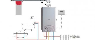
The widespread use of electric boilers is currently limited only by the high cost of maintaining an electric heating system. And yet, in cases where there is no gas and you don’t want to bother with coal, electric boilers are used in water heating systems. Photos of systems using them are given in the photo gallery section.
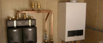
Electric boilers of JSC GALAN, due to their unique design solutions, are effectively used both in combined heating systems and independently, being the main and only source of thermal energy. They are easily integrated into existing heating systems with minimal additional costs for the consumer, since they do not contain classical elements: a circulation pump, a membrane expansion tank, or a protective group. The listed elements are already built into a modern heating system. And GALAN electric boilers only effectively complement it.
What was not used recently is now being implemented and used effectively. Electrode electric boilers are used in closed two-pipe (one-pipe) heating systems. Of course, with full and absolute compliance with the rules and regulations for the installation of such systems.
When using GALAN electric boilers independently, the heating system is built according to classical schemes, using all the necessary elements.
Some difficulties arise when starting heating systems based on electrode electric boilers (it is necessary to follow the procedure for starting an electrode boiler in accordance with the operating manual). Nevertheless, in view of the fact that an electrode electric boiler is more economical than a heating element by at least 20 - 25%, and this has been tested by installation and operation practice for more than 25 years, the schemes for their use are constantly expanding and improving.
Typical connection diagrams for GALAN electric boilers
Schematic diagram for connecting the electric boiler “GALAN”
1. Electric boiler “GALAN” 2. Automation “GALAN” 3. Safety group 4. Expansion tank 5. Ball valve 6. Filter 7. Circulation pump 8. Drain valve
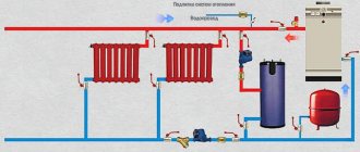
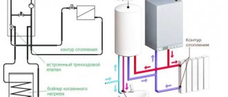
Diagram of parallel connection of the electric boiler “GALAN”
1. Electric boiler “GALAN” 2. Automation “GALAN” 3. Safety group 4. Expansion tank 5. Ball valve 6. Filter 7. Circulation pump 8. Drain valve 9. Other heat source (gas, oil or solid fuel boiler)
Connection diagram of the electric boiler “GALAN” to the riser
1. Electric boiler “GALAN” 2. Automation “GALAN” 3. Safety group 4. Expansion tank 5. Ball valve 6. Filter 7. Circulation pump 8. Drain valve
Connection diagram of the electric boiler “GALAN” to the radiator + floor heating
1. Electric boiler “GALAN” 2. Automation “GALAN” 3. Safety group 4. Expansion tank 5. Ball valve 6. Filter 7. Circulation pump 8. Drain valve 9. Three-way valve 10. Automatic floor heating 11. Floor heating circuit
Attention!
The area of the heated floor should not exceed 30% of the total heated area.
Connection diagram of the GALAN electric boiler to floor heating
1. Electric boiler “GALAN” 2. Automation “GALAN” 3. Safety group 4. Expansion tank 5. Ball valve 6. Filter 7. Circulation pump 8. Drain valve 9. Bypass 10. Circuit motor 11. Room thermostat 12. Heating circuit gender
Room thermostat and energy saving
To get a more functional option, let’s add here a device for monitoring the air temperature in the room - a room thermostat.
It doesn’t matter to him what the temperature of the boiler water will be; he reacts precisely to the comfortable air temperature in your home. By analogy with the previous elements, mount it in the gap, in front of the working thermostat
The second simplest scheme is ready
By analogy with the previous elements, mount it in the gap, in front of the working thermostat. The second simplest scheme is ready.
But people always strive for more, and in addition to the comfort of electric heating, they always want to save money. Still, with rare exceptions, electric heating is not exactly a cheap thing in our realities.
How to do this by improving the above connection diagram? There is a night rate for this business.
To take full advantage of it, we need a time relay.
It will start electric heating only during a specified period of the day. Place it in the circuit in front of the room thermostat.
However, pay attention to one nuance. If there is such a device in the circuit, a minimum air temperature thermostat must be mounted parallel to it.
During the day, in your absence, the temperature outside can drop sharply. We left at -5C, arrived in the evening - minus 25C outside. Accordingly, your home will become significantly colder.
It will start heating as soon as the temperature in the house drops below the minimum threshold. As a result, it will prevent the house from cooling down and the system from defrosting.
To visually observe whether the sensors are turned on or off at the moment, you can connect a signal light to a common point in front of the microswitches and display it in a visible place.
This is especially useful when the control panel and the boiler itself are located in the basement of the house or in a neighboring outbuilding.
Most factory electric heating boilers are built precisely on such basic control schemes. There is one supply line (phase) that supplies a signal to the coil of the device with power elements, and all additional equipment, sensors and switches are “hung” on this very line, performing protective and monitoring functions.
As you can see, there is nothing complicated or intricate here.
https://youtube.com/watch?v=fw9BUOGXT4Y%3F
Electric boilers “RESOURCE” EVPM
Electric heating boilers EVPM (electric heating boilers) are designed for water heating of buildings and residential premises with an open or closed heating system operating at a pressure of no more than 0.25 MPa, with a three-phase supply voltage of 380 V or a single-phase network of 220 V. Electric boilers can be used autonomously or in conjunction with heating boilers running on solid fuel.
Installation of an electric boiler in a heating system must be carried out by specialists with appropriate qualifications. Electric boilers are connected using an installation wire or cable in a metal sleeve (pipe).
Electric heating boilers (electric heating boilers) can be equipped with a remote control panel designed to regulate the coolant temperature.
| Model | Voltage, V | power, kWt | Productivity, m3/h | Switch power | Dimensions | Weight, kg |
| EVPM – 3 | 220 | 3 | 25-30 | 1/2/3 | 170x230x550 | 6 |
| EVPM – 4.5 | 220 | 4,5 | 35-45 | 1,5/3/4,5 | 170x230x550 | |
| EVPM – 6 | 220/380 | 6 | 55-60 | 2/4/6 | 170x230x550 | 8 |
| EVPM – 9 | 380 | 9 | 80-90 | 3/6/9 | 170x230x650 | 10 |
| EVPM – 12 | 380 | 12 | 105-120 | 4/8/12 | 170x230x650 | 12 |
| EVPM – 15 | 380 | 15 | 142-150 | 5/10/15 | 170x230x650 | |
| EVPM – 24 | 380 | 24 | 220-240 | 12/24 | 220x320x720 | 36 |
| EVPM – 36 | 380 | 36 | 345-360 | 12/24/36 | 220x360x720 | 36 |
| EVPM – 48 | 380 | 48 | 460-480 | 12/24/36/48 | 220x360x720 | 38 |
All “RESURS” electric boilers are equipped with a thermostat. Outlet water temperature – +35…+85°С.
Adjusting the water temperature
Besides security, we need one more element. A control element that will periodically turn it on and off to maintain the set water temperature.
This device is a working thermostat.
Don't confuse it with the ultimate. In the limit there is a manually reset button, which, when triggered, prevents the sensor from turning on independently.
That is, when it triggered once, you will need to inspect the entire system and circuit in order to understand the reason for the triggering. And only after that, by pressing this button, the heating can be started again.
The working thermostat turns on and off without your participation, depending on the temperature set on it.
This thermostat is installed after the limit, again in an open circuit.
Thus we received a security element and a control element. In principle, this is the most primitive scheme No. 1 for automatic electric heating.
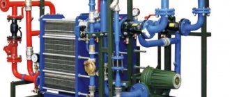
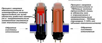
Design and principle of operation of an electric heating boiler
An electric heating boiler consists of a housing, a steel tank and a control panel mounted inside the housing. Tubular electric heaters (TEH) are mounted on the flange of the reservoir of the electric boiler, and in the upper part of the reservoir there is a temperature-sensitive tube for the temperature regulator.
The upper and lower pipes of the electric heating boiler are designed to connect the water heater to the heating system. On the front side of the electric boiler there is a temperature control knob, a power indicator and key switches. On the side of the body of the electric heating boiler there are holes for entering the power cable and ground wire, as well as for a remote temperature sensor.
Boiler selection
The choice of boiler unit for heat supply is made according to thermal power, electrical network parameters and the principle of the heating element. The price of the heating set depends on the last parameter. Such electric units have increased functionality - all models are equipped with block automation with a temperature controller.
Modern modifications of electric boilers are implemented with various peripheral devices - weather-sensitive sensors, room thermostats and GSM modules for adjusting the indoor temperature at a distance from a mobile phone via the Internet.
The level of assembly of block units is very high, which allows you to install such heating with your own hands. The only exception is the installation and adjustment of power supply lines to the unit, which must be performed by certified specialists.
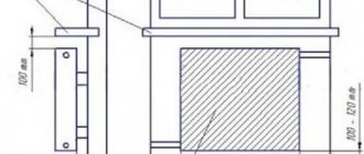
For example, for a house with a total area of 150 m2, the boiler power will be required: 150x1.2x0.1= 18 kW.
Calculation of heating costs
As mentioned above, an electric three-phase boiler is economically more expensive than its gas and solid fuel counterparts. Electricity is becoming more expensive by leaps and bounds.
Electric boiler wiring diagram
Calculate consumption for a month or heating season in the following way:
- Considering that the efficiency of most units is close to 100%, it is believed that to obtain a kilowatt of thermal energy, 1.03 kW of electrical energy will be required;
- the area of the house is divided by 10 and multiplied by this indicator;
- multiply the resulting value by the cost of one kW/h. (it varies in different regions), then by 24 (the number of operating hours per day) and the number of days in a month or heating season.
In theory, for a house of 100 square meters with a cost of 3.2 rubles per kilowatt and round-the-clock operation per month, approximately 26 thousand rubles will be required for heating. In practice, this amount should be reduced by approximately half - the boiler does not always work around the clock. The costs will be even lower for an apartment.
The video shows the installation procedure:
The material from which the house is built, the type of floors, the type of windows and doors, and the quality of insulation have a great influence. It is not possible to take everything into account. Therefore, only practice will show how expensive the boiler will be.
Advantages of an electric boiler
The electric three-phase boiler is constantly being improved by developers. Wall and floor models are available.
The best representatives of this class receive additional systems and devices that provide multi-stage adjustment, automation of air exhaust and temperature control processes.
An electric three-phase heating boiler can work in conjunction with other types of heaters. Compactness and design are considered an indisputable advantage.
Although an electric heater is not as economically profitable as, say, a gas heater, it still has certain advantages:
- An electric boiler takes up less space compared to a solid fuel boiler. It can be installed in any place where there is an electrical network;
- No chimney or additional ventilation is required - this is a direct saving of money and time on maintenance;
- It is not a source of unpleasant odors and carbon monoxide. The boiler is environmentally friendly.
- Makes almost no noise during operation;
- The absence of open flames makes it easier to comply with fire safety measures.
Electric boilers have a high efficiency of at least 96%.
The disadvantage of a three-phase boiler is the need to convert the current to 380 V and the presence of good electrical wiring in the house. Electricity is more expensive than gas, and frequent power surges affect the quality of boiler operation. This also applies to the disadvantages.
Types of three-phase heaters
The three-phase boiler is characterized by increased productivity, quiet operation and compact size.
Homemade induction heater
Most often used for heat and hot water supply systems in country houses. Double-circuit models are especially popular. It is recommended to install in combination with other heaters.
Available in two types:
- Electrode. The advantage of such a boiler is the high heating rate of the coolant.
- Induction. This is the most innovative type. Provides low specific energy consumption. The disadvantages include the large mass and relatively high price of the equipment. Such units are not produced with high power. To expand it, the method of cascading installation of three heaters at once is used, in which each boiler is connected to a separate phase.
Boilers with heating elements are also produced, but their popularity in private households is declining. Heating elements have to be cleaned and replaced frequently.
Operating rules
Despite the fact that an electric boiler is rightfully considered one of the safest, do not neglect compliance with safety precautions during operation. This is especially true when it comes to connectivity.
- The connection is made directly to the meter through network circuit breakers. The protection ensures safe shutdown of the heater in the event of a short circuit and sudden voltage drops.
- Proper grounding is mandatory. The manufacturer's instructions contain a diagram, failure to comply with which will result in a waiver of warranty obligations.